tow NISSAN GT-R 1998 Service Manual
[x] Cancel search | Manufacturer: NISSAN, Model Year: 1998, Model line: GT-R, Model: NISSAN GT-R 1998Pages: 230, PDF Size: 12.66 MB
Page 14 of 230

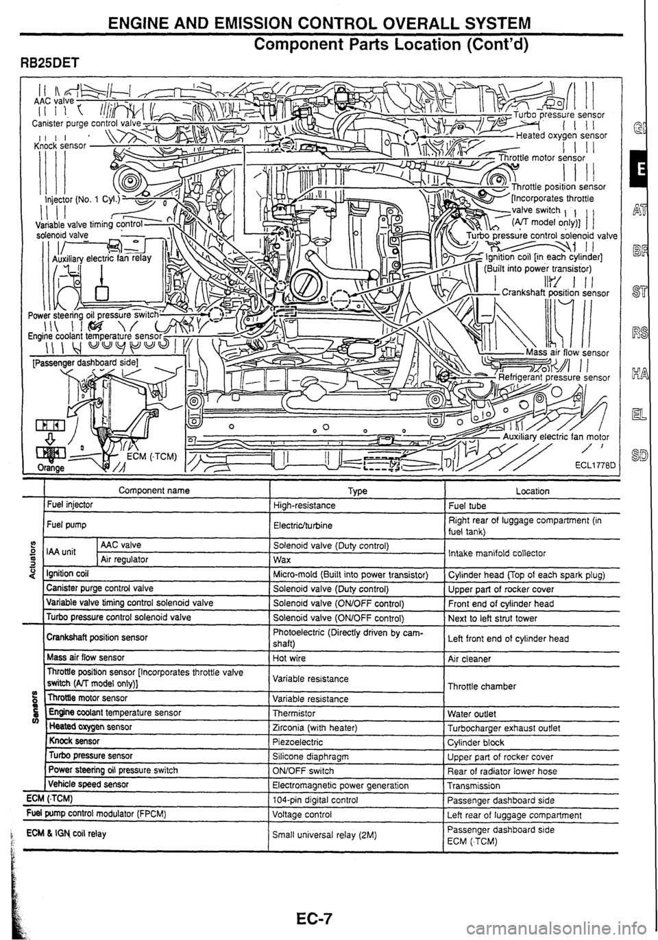
ENGINE AND EMISSION CONTROL OVERALL SYSTEM
Component
Parts Location (Cont'd)
" . . ., . .7
Comoonent name I TVLE a r Fuel injector High-resistance
Fuel pump
Electriclturbine
5 I unit I AAC valve I Solenoid valve (Duty control)
S Air reoulator 1 wax -1 I " - . -.
4 Ignition coil I Micro-mold (Built into power transistor)
I Canister purge control valve I Solenoid valve (Dutv control) ---- - Variable valve timing control solenold valve I Solenold valve (ONtOFF control)
Turbo pressure control solenoid valve
I Solenoid valve (OMOFF control)
Crankshaft position sensor Photoelectric
(Directly driven by cam-
shaft)
Mass air flow sensor
Hot wire
Throttle position sensor [Incorporates throttle valve
switch
(AlT model only)] Variable
resistance
Throttle motor sensor
09 Variable resistance
5 Engine coolant temperature sensor Thermistor V) Heated oxygen sensor
Zirconia (with heater)
Knock sensor Piezoelectric
Turbo pressure sensor Silicone diaphragm
Power
steering oil pressure switch
ONJOFF switch
( Vehicle speed sensor
Electromagnetic power generation
ECM
(.TCM) 104-pin digital control
Fuel pump control modulator (FPCM)
Voltage control
1 ECM L IGN co~l relay Small un~versal relay (2M) P t
.
Fuel tube
Right rear of luggage compartment (in
fuel tank)
Intake manifold collector
Cvlinder head
UOD of each soark olua)
Upper part of rocker cover
Front end of cylinder head
Next to left strut tower
Left front end of cylinder head
Air cleaner
Throttle chamber
Water outlet
Turbocharaer exhaust outlet
Cylinder
block
Upper part of rocker cover
Rear of radiator lower hose
Transmission
Passenger dashboard side
Left rear of
luaaaae comoartment
-- Passenger dashboard s~de
ECM ( TCM)
Page 29 of 230
![NISSAN GT-R 1998 Service Manual
TROUBLE DIAGNOSES
CONSULT (Contd)
DATA MONITOR MODE
ECM input
signals
Monitored item
[Unit] Main
signals Remarks
Description
lndicates the engine speed computed
from the POS signal (l NISSAN GT-R 1998 Service Manual
TROUBLE DIAGNOSES
CONSULT (Contd)
DATA MONITOR MODE
ECM input
signals
Monitored item
[Unit] Main
signals Remarks
Description
lndicates the engine speed computed
from the POS signal (l](/img/5/57354/w960_57354-28.png)
TROUBLE DIAGNOSES
CONSULT (Cont'd)
DATA MONITOR MODE
ECM input
signals
Monitored item
[Unit] Main
signals Remarks
Description
lndicates the engine speed computed
from the POS signal (lo signal) of the
camshaft position sensor.
When the engine is stopped, a certain
value is indicated.
When the engine coolant temperature
sensor is open or short-circuited, ECM
enters fail-safe mode. The engine coolant
temperature determined by the ECM is
displayed.
The signai voltage of the mass air flow
0 sensor is displayed.
The engine coolant temperature (deter-
mined by the signal voltage of the engine
0 coolant temperature sensor) is displayed.
-
MAS AIRiFL SE [V]
The signal voltage of the oxygen sensor
is displayed.
02
SEN [V]'
0 After turning ON the ignition switch, "RICH" is displayed until air-fuel mixture
ratio feedback control begins.
When the air-fuel ratio feedback is
clamped, the value just before the clamp-
ing is displayed continuously.
MiR
F/C MNT*
[RICH/LEAN] Display of oxygen sensor signal during
air-fuel ratio feedback control:
RICH
... means the mixture became
"rich", and control is being affected
toward a leaner mixture.
LEAN
... means the mixture became
"lean", and control is being affected
toward
a rich mixture.
The vehicle speed computed from the
vehicle speed sensor signal is displayed. VHCL SPEED SE [krn/h] or [mph]
The power supply voltage of ECM is dis-
played. I BATTERY VOLT [V]
THRTL POS SEN [V] The throttle position sensor signal volt-
age is displayed.
Throttle motor sensor output voltage Approx. 4.6V THRTL POS SE2 [V] 0 RB25DET
TURBO BOOST
SENSOR
RB25DET
Turbo pressure sensor output voltage 0 Approx. 2.7V
Indicates [ON/OFF] condition from the After starting the engine, [OFF] is dis-
0 starter signal. played regardless of the starter signal.
lndicates [ON/OFF] condition from the 0 throttle position sensor signal.
-
START SIGNAL
[ON/OFF]
CLSD THUP SW
[0
N/O
FF]
0 lndicates [ON/OFF] condition of the air
conditioner switch as determined by the
air conditioner sianal. AIR COND SIG
[ON/OFF]
lndicates [ON/OFFj condition from the
parldneutral position switch signal.
PiN
POSl SW [ONIOFF)
PW/ST SIGNAL
[ONIOFF]
LOAD SIGNAL
[ON/OFF]
lndicates [ON/OFfl condition from the
electrical load signal
andlor lighting
switch.
ON ... rear defogger is operating.
OFF ... rear defogger is not operating.
NOTE: Any monitored item that does not match the vehicle being diagnosed is deleted from the display automatically. *: Models with three way catalyst.
Page 198 of 230

REAR WIPER
Component
Parts Location
Rear of suspension tower (RH)
Circuit Diagram
IGN :
Q
Rear washer motor
B Rear wiper motor I-
Washer motor operation
detection signal I
1 Rear wiper and washer SW
Intermittent position de!ection signal I ~SHIOFFI 111~~ INTI - ON IWIW~
I * Wiper motor operation signal
Rear Wiper Amplifier InputlOutput Signal
Specifications
Measuring condition
lanition
switch
/ O~eration
Terminal No.
Signal name Specification
Washer motor operation detection
signal
Wiper operation signal
Ground
Intermittent position detection signal
I ON I Wiper switch
Wlper
motor operation signal ON
ON
ON
ACC power
supply
I I I (Reference)
INT . Other than INT
Washer
motor is in operation.
Washer motor is not in operation.
Wiper motor is in operation.
Wiper motor is not
in operation.
-
Approx. OV
ARD~OX. 12V Approx.
OV
Approx.
12V
Approx. OV
Approx.
12V
AD~rox. OV
. .
Approx. 12V 1 I ON -