NISSAN LATIO 2008 Service Repair Manual
LATIO 2008
NISSAN
NISSAN
https://www.carmanualsonline.info/img/5/57360/w960_57360-0.png
NISSAN LATIO 2008 Service Repair Manual
Trending: towing, center console, fuse box location, fold seats, horn, light, engine oil
Page 2591 of 2771
STARTING SYSTEM
SC-9
< SERVICE INFORMATION >
C
D
E
F
G
H
I
J
L
MA
B
SC
N
O
P
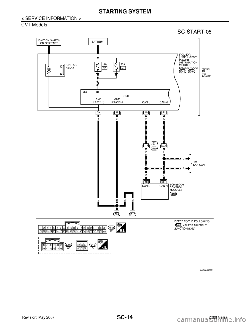
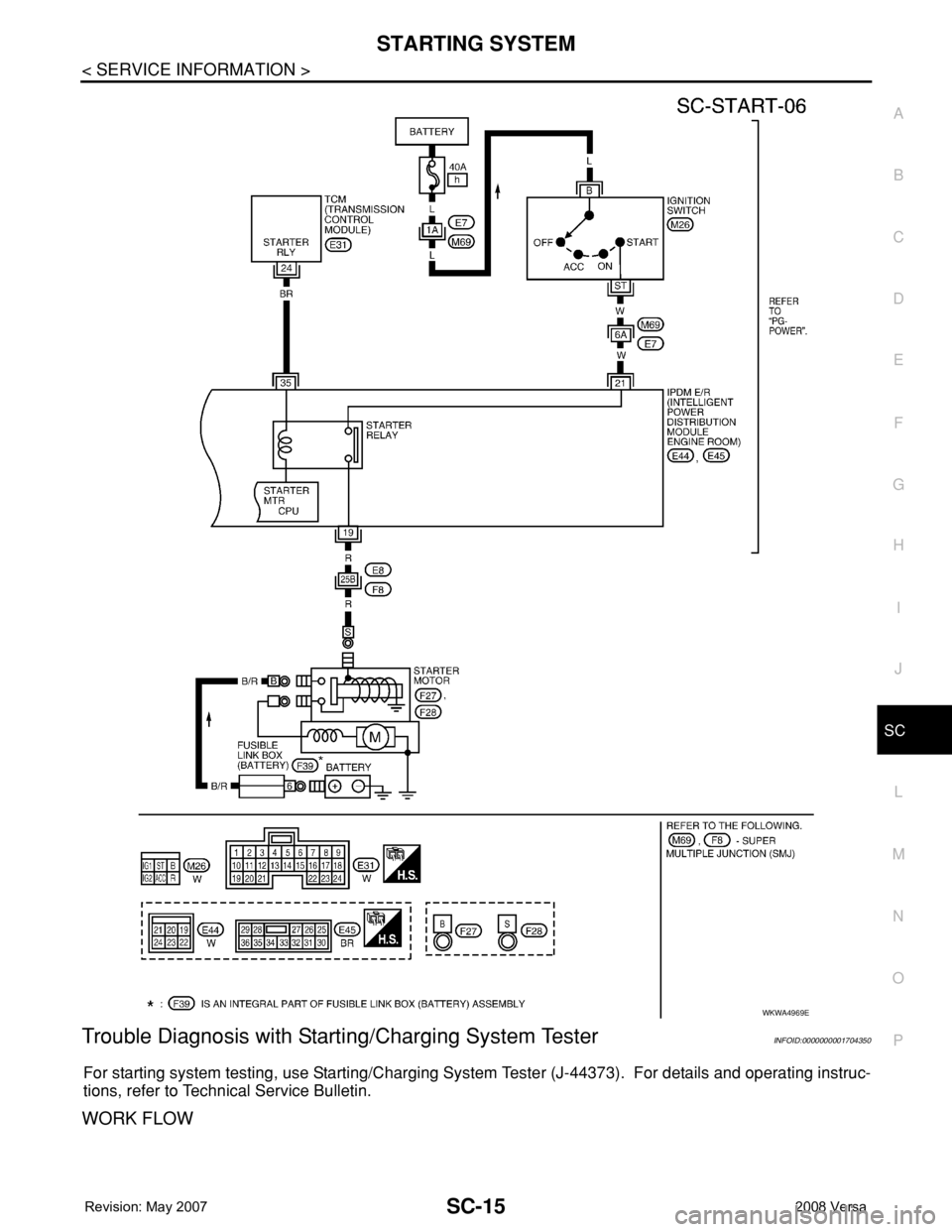
• to IPDM E/R terminal 21.
With the selector lever in the P or N position, power is supplied
• from the transmission control module (TCM) terminal 24
• to IPDM E/R terminal 35.
Ground is supplied at all times
• to IPDM E/R terminals 39 and 59
• through body grounds E15 and E24.
If the IPDM E/R receives a starter relay request ON signal from the BCM over the CAN network, the IPDM E/
R grounds the starter relay and power is supplied
• through terminal 19 of the IPDM E/R
• to terminal S of the starter motor.
The starter motor magnetic switch energizes closing the circuit between the battery and the starter motor. The
starter motor is case ground through the cylinder block. With power and ground supplied, the starter motor
operates.
Page 2592 of 2771
SC-10
< SERVICE INFORMATION >
STARTING SYSTEM
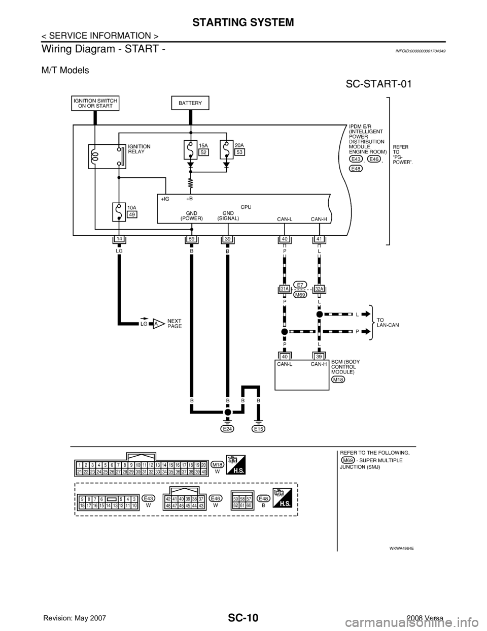
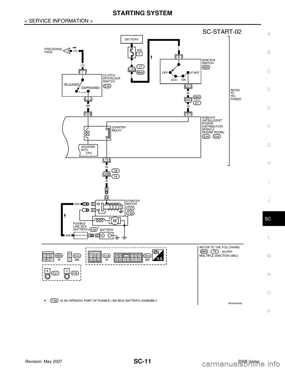
Wiring Diagram - START -
INFOID:0000000001704349
M/T Models
WKWA4964E
Page 2593 of 2771
STARTING SYSTEM
SC-11
< SERVICE INFORMATION >
C
D
E
F
G
H
I
J
L
MA
B
SC
N
O
P
WKWA4965E
Page 2594 of 2771
SC-12
< SERVICE INFORMATION >
STARTING SYSTEM
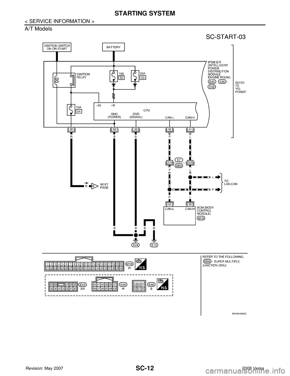
A/T Models
WKWA4966E
Page 2595 of 2771
STARTING SYSTEM
SC-13
< SERVICE INFORMATION >
C
D
E
F
G
H
I
J
L
MA
B
SC
N
O
P
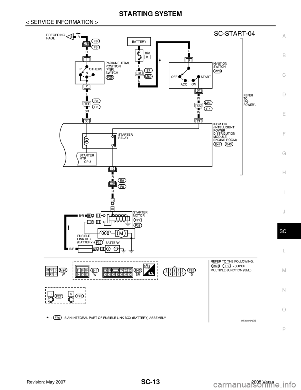
WKWA4967E
Page 2596 of 2771
SC-14
< SERVICE INFORMATION >
STARTING SYSTEM
CVT Models
WKWA4968E
Page 2597 of 2771
STARTING SYSTEM
SC-15
< SERVICE INFORMATION >
C
D
E
F
G
H
I
J
L
MA
B
SC
N
O
P
Trouble Diagnosis with Starting/Charging System TesterINFOID:0000000001704350
For starting system testing, use Starting/Charging System Tester (J-44373). For details and operating instruc-
tions, refer to Technical Service Bulletin.
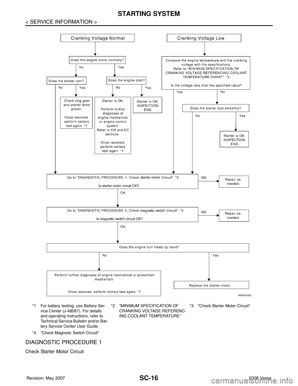
WORK FLOW
WKWA4969E
Page 2598 of 2771
SC-16
< SERVICE INFORMATION >
STARTING SYSTEM
DIAGNOSTIC PROCEDURE 1
Check Starter Motor Circuit
*1 For battery testing, use Battery Ser-
vice Center (J-48087). For details
and operating instructions, refer to
Technical Service Bulletin and/or Bat-
tery Service Center User Guide.*2 "MINIMUM SPECIFICATION OF
CRANKING VOLTAGE REFERENC-
ING COOLANT TEMPERATURE"*3 "Check Starter Motor Circuit"
*4 "Check Magnetic Switch Circuit"
WKIA4532E
Page 2599 of 2771
STARTING SYSTEM
SC-17
< SERVICE INFORMATION >
C
D
E
F
G
H
I
J
L
MA
B
SC
N
O
P
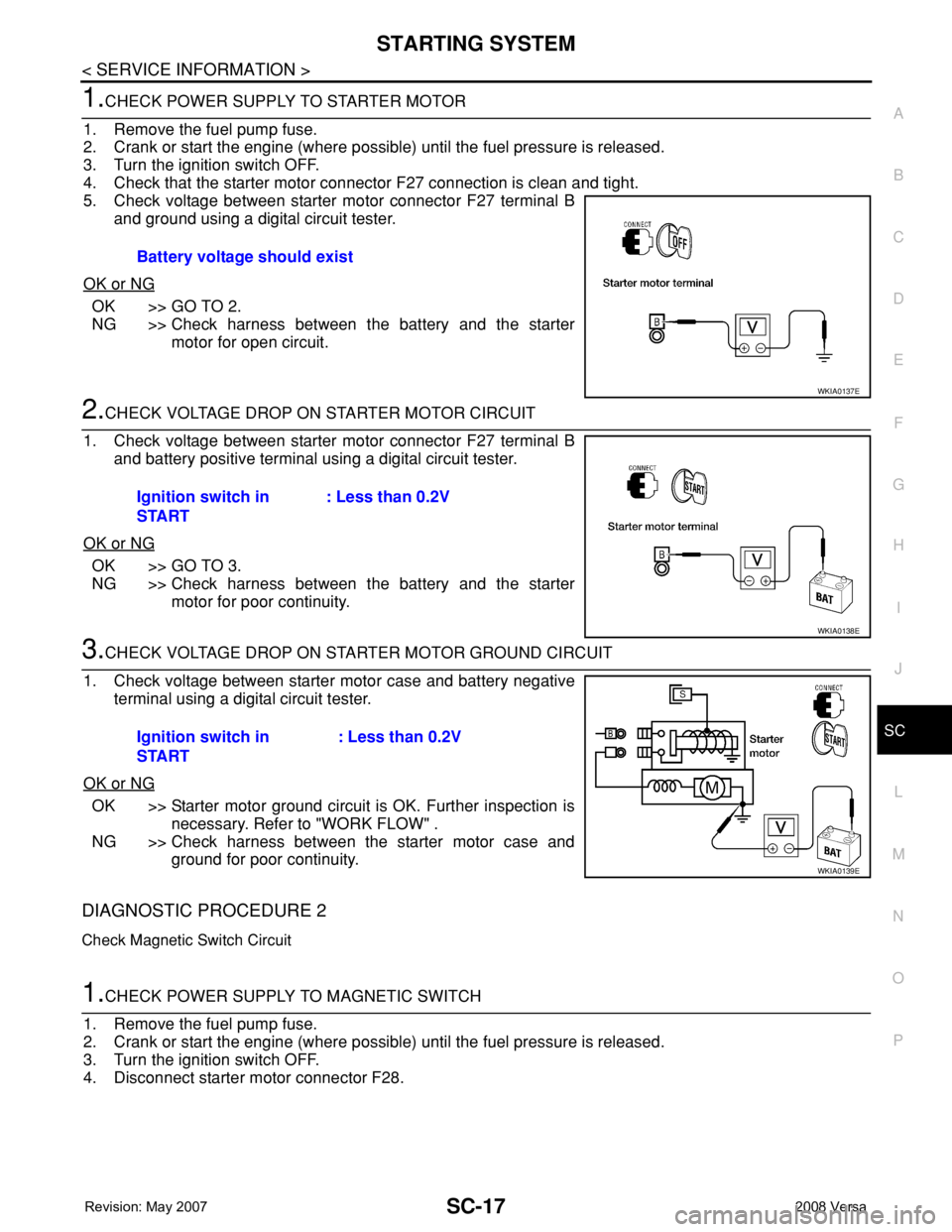
1.CHECK POWER SUPPLY TO STARTER MOTOR
1. Remove the fuel pump fuse.
2. Crank or start the engine (where possible) until the fuel pressure is released.
3. Turn the ignition switch OFF.
4. Check that the starter motor connector F27 connection is clean and tight.
5. Check voltage between starter motor connector F27 terminal B
and ground using a digital circuit tester.
OK or NG
OK >> GO TO 2.
NG >> Check harness between the battery and the starter
motor for open circuit.
2.CHECK VOLTAGE DROP ON STARTER MOTOR CIRCUIT
1. Check voltage between starter motor connector F27 terminal B
and battery positive terminal using a digital circuit tester.
OK or NG
OK >> GO TO 3.
NG >> Check harness between the battery and the starter
motor for poor continuity.
3.CHECK VOLTAGE DROP ON STARTER MOTOR GROUND CIRCUIT
1. Check voltage between starter motor case and battery negative
terminal using a digital circuit tester.
OK or NG
OK >> Starter motor ground circuit is OK. Further inspection is
necessary. Refer to "WORK FLOW" .
NG >> Check harness between the starter motor case and
ground for poor continuity.
DIAGNOSTIC PROCEDURE 2
Check Magnetic Switch Circuit
1.CHECK POWER SUPPLY TO MAGNETIC SWITCH
1. Remove the fuel pump fuse.
2. Crank or start the engine (where possible) until the fuel pressure is released.
3. Turn the ignition switch OFF.
4. Disconnect starter motor connector F28.Battery voltage should exist
WKIA0137E
Ignition switch in
START: Less than 0.2V
WKIA0138E
Ignition switch in
START: Less than 0.2V
WKIA0139E
Page 2600 of 2771
SC-18
< SERVICE INFORMATION >
STARTING SYSTEM
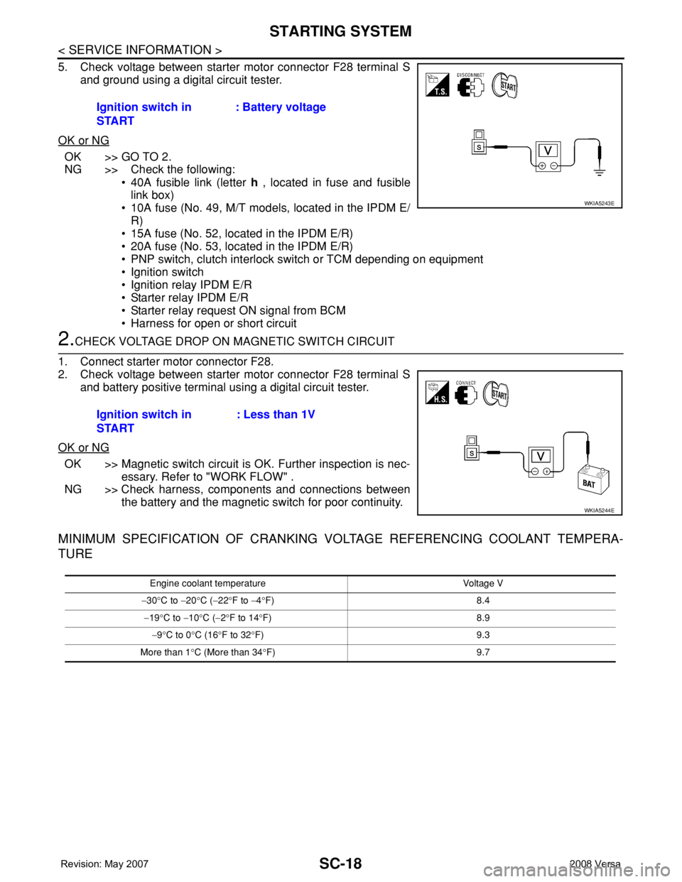
5. Check voltage between starter motor connector F28 terminal S
and ground using a digital circuit tester.
OK or NG
OK >> GO TO 2.
NG >> Check the following:
• 40A fusible link (letter h , located in fuse and fusible
link box)
• 10A fuse (No. 49, M/T models, located in the IPDM E/
R)
• 15A fuse (No. 52, located in the IPDM E/R)
• 20A fuse (No. 53, located in the IPDM E/R)
• PNP switch, clutch interlock switch or TCM depending on equipment
• Ignition switch
• Ignition relay IPDM E/R
• Starter relay IPDM E/R
• Starter relay request ON signal from BCM
• Harness for open or short circuit
2.CHECK VOLTAGE DROP ON MAGNETIC SWITCH CIRCUIT
1. Connect starter motor connector F28.
2. Check voltage between starter motor connector F28 terminal S
and battery positive terminal using a digital circuit tester.
OK or NG
OK >> Magnetic switch circuit is OK. Further inspection is nec-
essary. Refer to "WORK FLOW" .
NG >> Check harness, components and connections between
the battery and the magnetic switch for poor continuity.
MINIMUM SPECIFICATION OF CRANKING VOLTAGE REFERENCING COOLANT TEMPERA-
TURE
Ignition switch in
START: Battery voltage
WKIA5243E
Ignition switch in
START: Less than 1V
WKIA5244E
Engine coolant temperature Voltage V
−30°C to −20°C (−22°F to −4°F) 8.4
−19°C to −10°C (−2°F to 14°F) 8.9
−9°C to 0°C (16°F to 32°F) 9.3
More than 1°C (More than 34°F) 9.7
Trending: key battery, horn, ad blue, center console, spare wheel, length, tires

