sensor NISSAN LATIO 2009 Service Repair Manual
[x] Cancel search | Manufacturer: NISSAN, Model Year: 2009, Model line: LATIO, Model: NISSAN LATIO 2009Pages: 4331, PDF Size: 58.04 MB
Page 3888 of 4331

MTC
N
O P
SERVICE INFORMATION
PRECAUTIONS
Precaution for Supplemental Restraint System (SRS) "AIR BAG" and "SEAT BELT
PRE-TENSIONER" INFOID:0000000004784399
The Supplemental Restraint System such as “A IR BAG” and “SEAT BELT PRE-TENSIONER”, used along
with a front seat belt, helps to reduce the risk or severi ty of injury to the driver and front passenger for certain
types of collision. This system includes seat belt switch inputs and dual stage front air bag modules. The SRS
system uses the seat belt switches to determine the front air bag deployment, and may only deploy one front
air bag, depending on the severity of a collision and w hether the front occupants are belted or unbelted.
Information necessary to service the system safely is included in the SRS and SB section of this Service Man-
ual.
WARNING:
• To avoid rendering the SRS inoper ative, which could increase the risk of personal injury or death in
the event of a collision which would result in air bag inflation, all maintenance must be performed by
an authorized NISSAN/INFINITI dealer.
• Improper maintenance, including in correct removal and installation of the SRS can lead to personal
injury caused by unintentional act ivation of the system. For removal of Spiral Cable and Air Bag
Module, see the SRS section.
• Do not use electrical test equipm ent on any circuit related to the SRS unless instructed to in this
Service Manual. SRS wiring harnesses can be identi fied by yellow and/or orange harnesses or har-
ness connectors.
PRECAUTIONS WHEN USING POWER TOOLS (AIR OR ELECTRIC) AND HAMMERS WARNING:
• When working near the Airbag Diagnosis Sensor Un it or other Airbag System sensors with the Igni-
tion ON or engine running, DO NOT use air or el ectric power tools or strike near the sensor(s) with a
hammer. Heavy vibration could activate the sensor( s) and deploy the air bag(s), possibly causing
serious injury.
• When using air or electric power tools or hammers , always switch the Ignition OFF, disconnect the
battery, and wait at least 3 minutes before performing any service.
Precaution Necessary for Steering Wh eel Rotation After Battery Disconnect
INFOID:0000000004687764
NOTE:
• This Procedure is applied only to models with Inte lligent Key system and NATS (NISSAN ANTI-THEFT SYS-
TEM).
• Remove and install all control units after disconnecti ng both battery cables with the ignition knob in the
″ LOCK ″ position.
• Always use CONSULT-III to perform self-diagnosis as a part of each function inspection after finishing work.
If DTC is detected, perform trouble diagnosis according to self-diagnostic results.
For models equipped with the Intelligent Key system and NATS , an electrically controlled steering lock mech-
anism is adopted on the key cylinder.
For this reason, if the battery is disconnected or if the battery is discharged, the steering wheel will lock and
steering wheel rotation will become impossible.
If steering wheel rotation is required when battery pow er is interrupted, follow the procedure below before
starting the repair operation.
OPERATION PROCEDURE 1. Connect both battery cables. NOTE:
Supply power using jumper cables if battery is discharged.
2. Use the Intelligent Key or mechanical key to turn the ignition switch to the ″ACC ″ position. At this time, the
steering lock will be released.
3. Disconnect both battery cables. The steering lock will remain released and the steering wheel can be
rotated.
4. Perform the necessary repair operation.
Page 3890 of 4331
MTC
N
O P
been shown to be combustible at
elevated pressures. These mixtures, if ignited, may cause injury or
property damage. Additional health and safety info rmation may be obtained from refrigerant manu-
facturers.
Oil Precaution INFOID:0000000004307045
• Use only specified oil for the HFC-134a (R-134a) A/C system and HFC-134a (R-134a) components. If oil
other than that specified is used, comp ressor malfunction is likely to occur.
• The specified HFC-134a (R-134a) oil rapidly absorbs mo isture from the atmosphere. The following handling
precautions must be observed:
- When removing refrigerant components from a vehicle, immediately cap (seal) the component to minimize the entry of moisture from the atmosphere.
- When installing refrigerant components to a vehicle, do not remove the caps (unseal) until just before con- necting the components. Connect all refrigerant loop components as quickly as possible to minimize the
entry of moisture into system.
- Only use the specified oil from a sealed container. Imm ediately reseal containers of oil. Without proper seal-
ing, oil will become moisture saturated and should not be used.
• Avoid breathing A/C refrigerant and oil vapor or mist. Exposure may irritate eyes, nose and throat.
Use only approved recovery/recycling equipment to discharge HFC-134a (R-134a) refrigerant. If accidental
system discharge occurs, ventilate work area before re suming service. Additional health and safety informa-
tion may be obtained from refrigerant and oil manufacturers.
• Do not allow A/C oil to come in contact with styrofoam parts. Damage may result.
Precaution for Refrigerant Connection INFOID:0000000004307046
A new type refrigerant connection has been introduced to a ll refrigerant lines except the following location.
• Expansion valve to evaporator
• Refrigerant pressure sensor to condenser
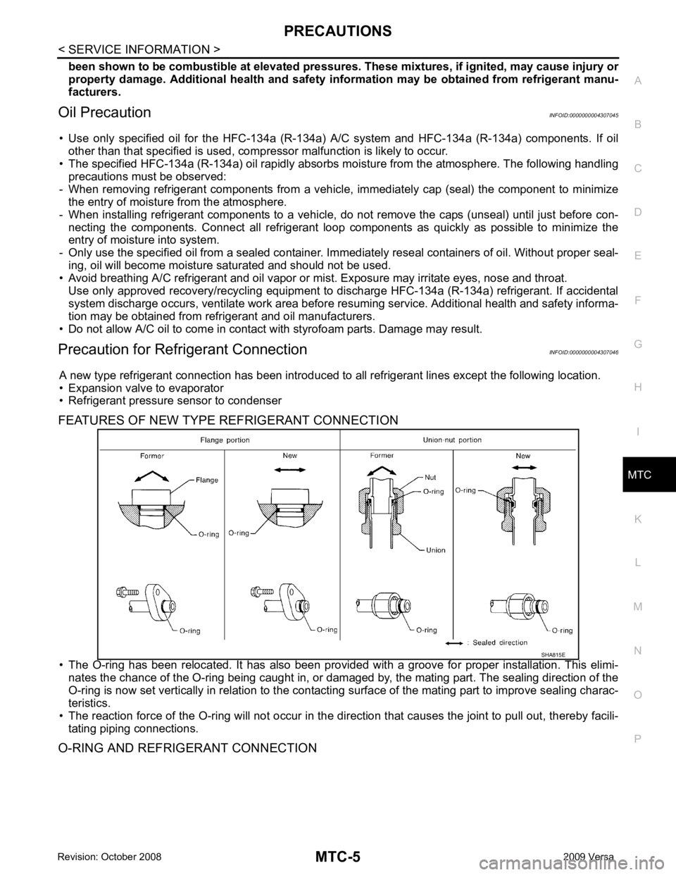
FEATURES OF NEW TYPE REFRIGERANT CONNECTION
• The O-ring has been relocated. It has also been provided with a groove for proper installation. This elimi- nates the chance of the O-ring being caught in, or damaged by, the mating part. The sealing direction of the
O-ring is now set vertically in relation to the contacti ng surface of the mating part to improve sealing charac-
teristics.
• The reaction force of the O-ring will not occur in the dire ction that causes the joint to pull out, thereby facili-
tating piping connections.
O-RING AND REFRIGERANT CONNECTION
Page 3892 of 4331
MTC
N
O P
O-Ring Part Numbers and Specifications
CAUTION:
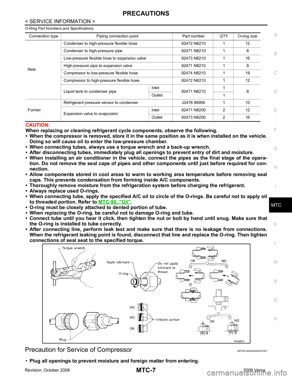
When replacing or cleaning refrigerant cycle components, observe the following.
• When the compressor is removed, store it in the sam e position as it is when installed on the vehicle.
Doing so will cause oil to en ter the low-pressure chamber.
• When connecting tubes, always use a to rque wrench and a back-up wrench.
• After disconnecting tubes, immediately plug all op enings to prevent entry of dirt and moisture.
• When installing an air conditione r in the vehicle, connect the pipes as the final stage of the opera-
tion. Do not remove the seal caps of pipes and other components until just before required for con-
nection.
• Allow components stored in cool areas to warm to working area temperature before removing seal
caps. This prevents condensation from forming inside A/C components.
• Thoroughly remove moisture from the refriger ation system before charging the refrigerant.
• Always replace used O-rings.
• When connecting tube, apply the speci fied A/C oil to circle of the O-rings. Be careful not to apply oil
to threaded portion. Refer to MTC-90, " Oil " .
• O-ring must be closely attached to dented portion of tube.
• When replacing the O-ring, be careful not to damage O-ring and tube.
• Connect tube until you hear it cl ick, then tighten the nut or bolt by hand until snug. Make sure that
the O-ring is installed to tube correctly.
• After connecting line, perform leak test and make sure that there is no leakage from connections.
When the refrigerant leaking point is found, disconnect that line and replace the O-ring. Then tighten
connections of seal seat to the specified torque.
Precaution for Service of Compressor INFOID:0000000004307047
• Plug all openings to prevent moisture and foreign matter from entering.
Connection type Piping connection point Part number QTY O-ring size
New Condenser to high-pressure flexible hose 92472 N8210 1 12
Condenser to high-pressure pipe 92471 N8210 1 8
Low-pressure flexible hose to expansion valve 92473 N8210 1 16
High-pressure pipe to expansion valve 92471 N8210 1 8
Compressor to low-pressure flexible hose 92474 N8210 1 19
Compressor to high-pressure flexible hose 92472 N8210 1 12
Liquid tank to condenser pipe Inlet
92471 N8210 1
8
Outlet 1
Former Refrigerant pressure sensor to condenser J2476 89956 1 10
Expansion valve to evaporator Inlet 92471 N8200 2 12
Outlet 92473 N8200 2 16
Page 3900 of 4331
MTC
N
O P
REFRIGERATION SYSTEM
Refrigerant Cycle INFOID:0000000004307053
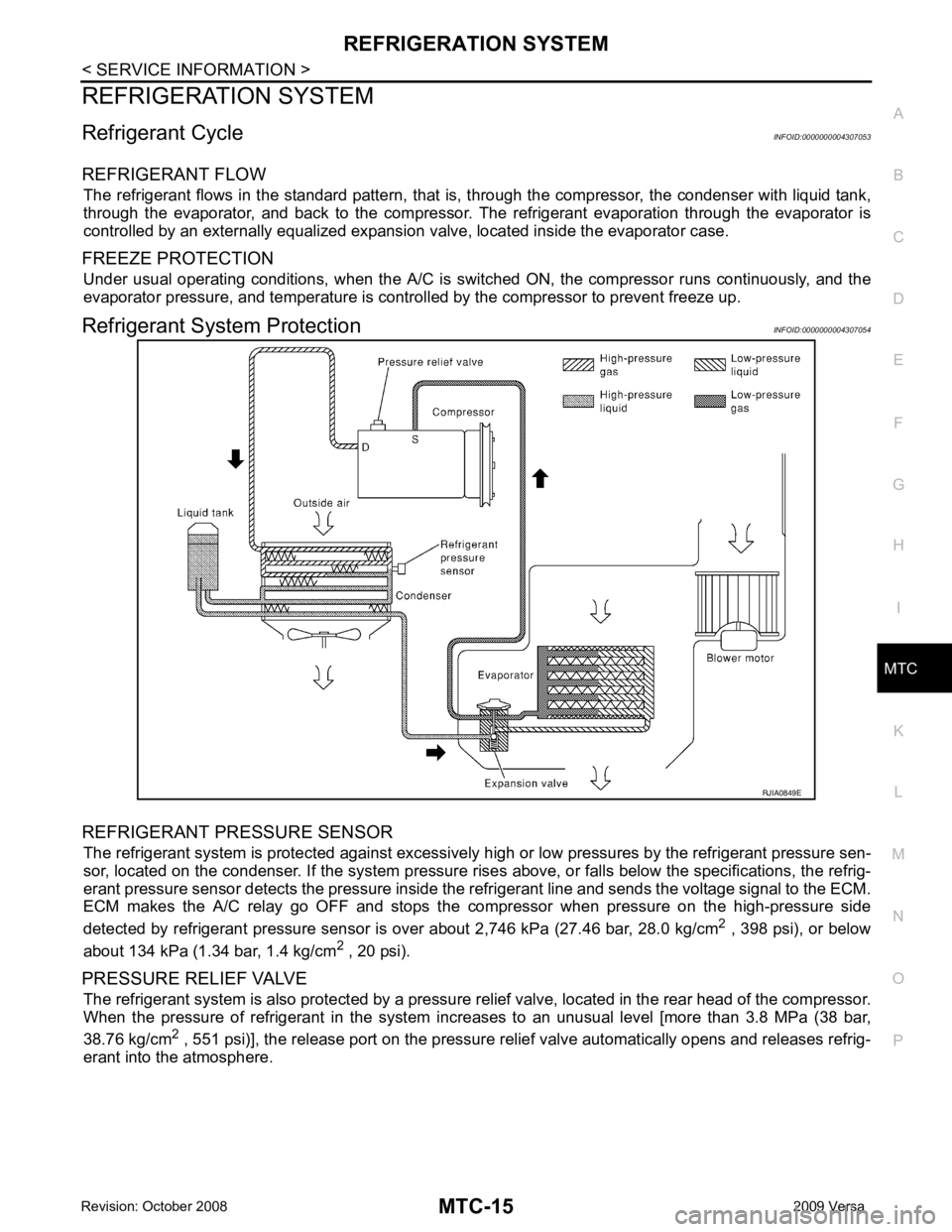
REFRIGERANT FLOW The refrigerant flows in the standard pattern, that is , through the compressor, the condenser with liquid tank,
through the evaporator, and back to the compressor. T he refrigerant evaporation through the evaporator is
controlled by an externally equalized expansion valve, located inside the evaporator case.
FREEZE PROTECTION Under usual operating conditions, when the A/C is s witched ON, the compressor runs continuously, and the
evaporator pressure, and temperature is controlled by the compressor to prevent freeze up.
Refrigerant System Protection INFOID:0000000004307054
REFRIGERANT PRESSURE SENSOR The refrigerant system is protected against excessively hi gh or low pressures by the refrigerant pressure sen-
sor, located on the condenser. If the system pressure rise s above, or falls below the specifications, the refrig-
erant pressure sensor detects the pressure inside t he refrigerant line and sends the voltage signal to the ECM.
ECM makes the A/C relay go OFF and stops the compressor when pressure on the high-pressure side
detected by refrigerant pressure sensor is over about 2,746 kPa (27.46 bar, 28.0 kg/cm 2
, 398 psi), or below
about 134 kPa (1.34 bar, 1.4 kg/cm 2
, 20 psi).
PRESSURE RELIEF VALVE The refrigerant system is also protected by a pressure relief valve, located in the rear head of the compressor.
When the pressure of refrigerant in the system in creases to an unusual level [more than 3.8 MPa (38 bar,
38.76 kg/cm 2
, 551 psi)], the release port on the pressure relief valve automatically opens and releases refrig-
erant into the atmosphere.
Page 3908 of 4331
MTC
N
O P
Component Parts and Har
ness Connector Location INFOID:0000000004307063
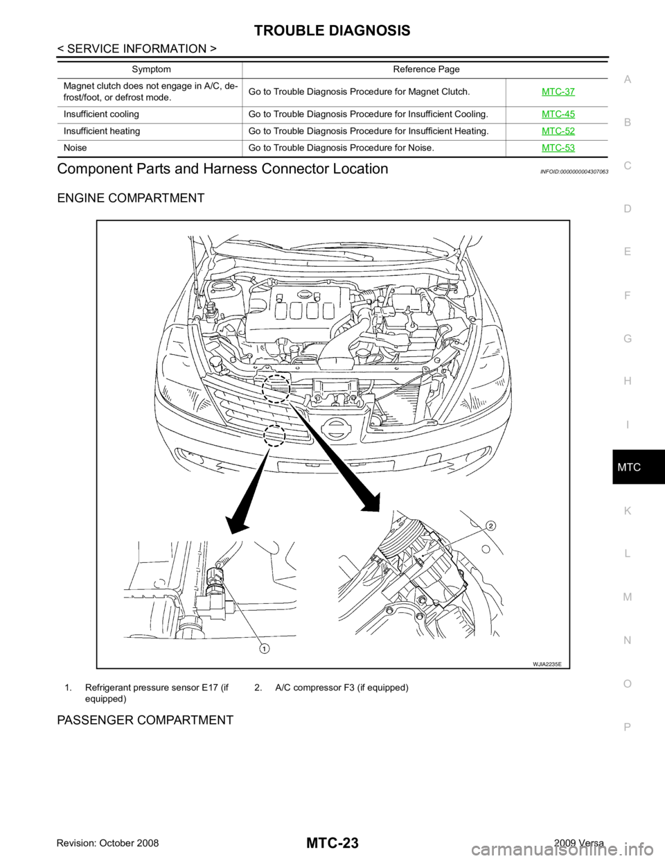
ENGINE COMPARTMENT
PASSENGER COMPARTMENT Magnet clutch does not engage in A/C, de-
frost/foot, or defrost mode. Go to Trouble Diagnosis Procedure for Magnet Clutch.
MTC-37Insufficient cooling Go to Trouble Diagnosis Procedure for Insufficient Cooling.
MTC-45Insufficient heating Go to Trouble Diagnosis Procedure for Insufficient Heating.
MTC-52Noise Go to Trouble Diagnosis Procedure for Noise.
MTC-53Symptom Reference Page
1. Refrigerant pressure sensor E17 (if
equipped) 2. A/C compressor F3 (if equipped)
Page 3968 of 4331
MTC
N
O P
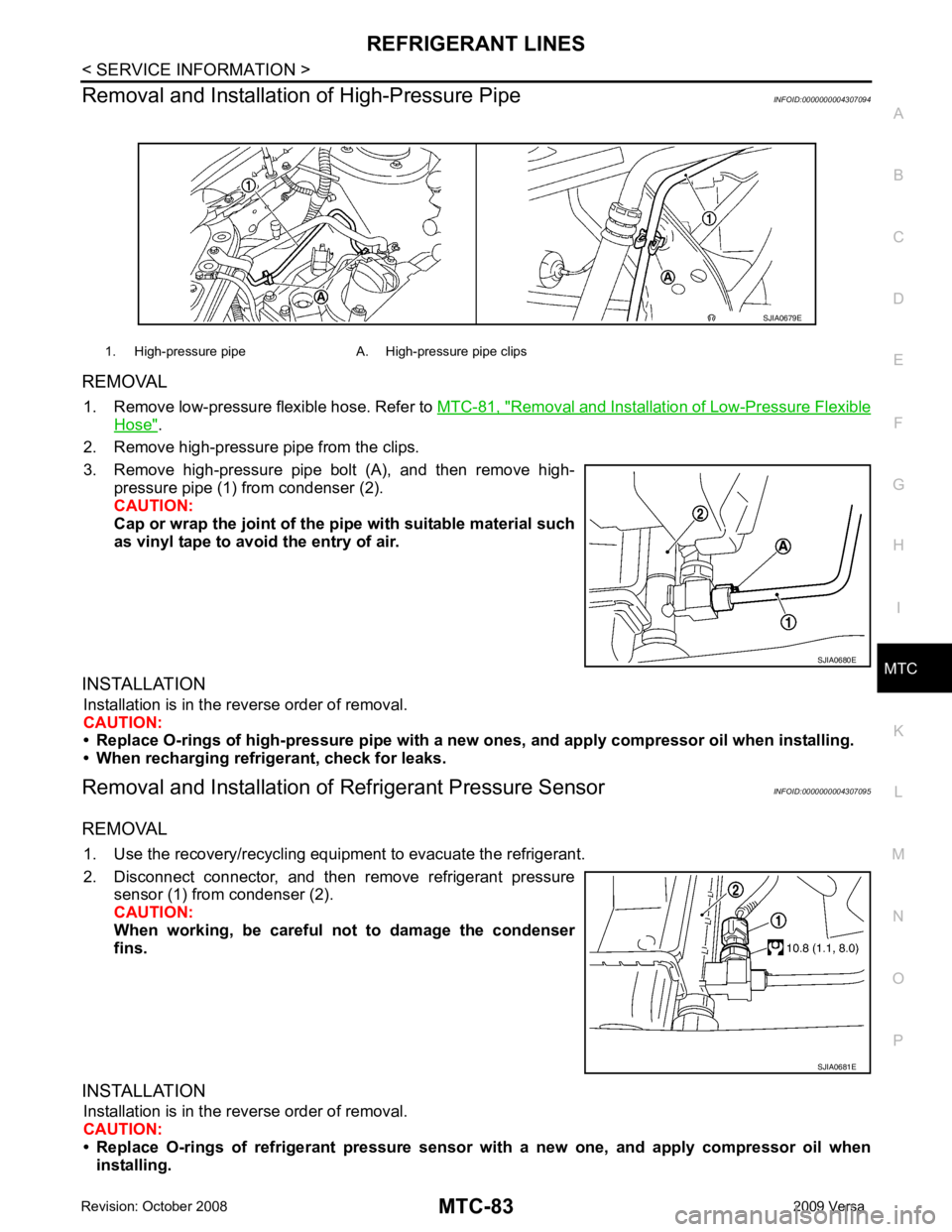
Removal and Installation of High-Pressure Pipe
INFOID:0000000004307094
REMOVAL 1. Remove low-pressure flexible hose. Refer to MTC-81, " Removal and Installation of Low-Pressure Flexible
Hose " .
2. Remove high-pressure pipe from the clips.
3. Remove high-pressure pipe bolt (A), and then remove high- pressure pipe (1) from condenser (2).
CAUTION:
Cap or wrap the joint of the pi pe with suitable material such
as vinyl tape to avoid the entry of air.
INSTALLATION Installation is in the reverse order of removal.
CAUTION:
• Replace O-rings of high-pressure pipe with a ne w ones, and apply compressor oil when installing.
• When recharging refrigerant, check for leaks.
Removal and Installation of Refrigerant Pressure Sensor INFOID:0000000004307095
REMOVAL 1. Use the recovery/recycling equipment to evacuate the refrigerant.
2. Disconnect connector, and then remove refrigerant pressure sensor (1) from condenser (2).
CAUTION:
When working, be careful not to damage the condenser
fins.
INSTALLATION Installation is in the reverse order of removal.
CAUTION:
• Replace O-rings of refrigerant pressure senso r with a new one, and apply compressor oil when
installing. 1. High-pressure pipe A. High-pressure pipe clips
Page 3969 of 4331
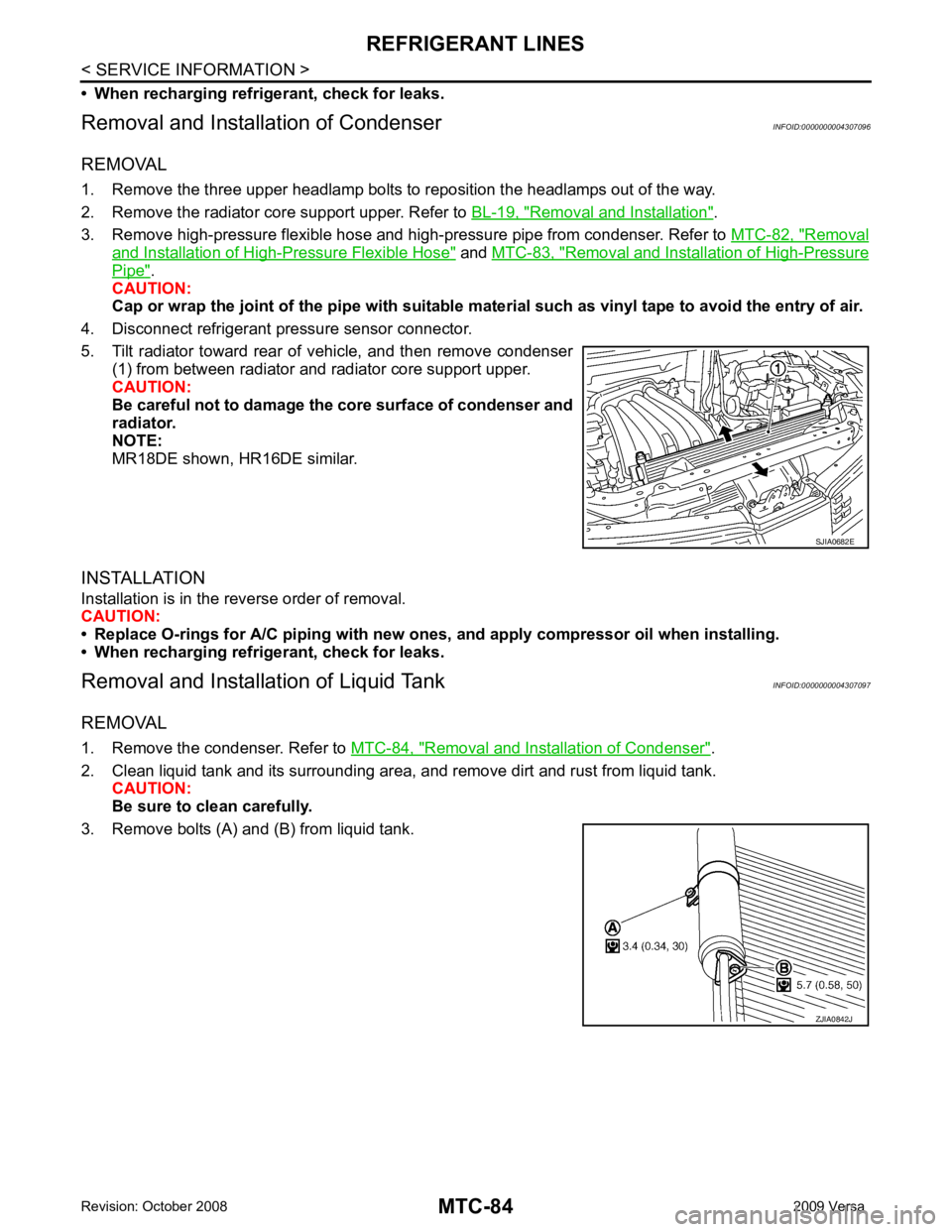
Removal and Installation " .
3. Remove high-pressure flexible hose and high-pressure pipe from condenser. Refer to MTC-82, " Removal
and Installation of High-Pressure Flexible Hose " and
MTC-83, " Removal and Installation of High-Pressure
Pipe " .
CAUTION:
Cap or wrap the joint of the pipe with suitable ma terial such as vinyl tape to avoid the entry of air.
4. Disconnect refrigerant pressure sensor connector.
5. Tilt radiator toward rear of vehicle, and then remove condenser (1) from between radiator and radiator core support upper.
CAUTION:
Be careful not to damage the core surface of condenser and
radiator.
NOTE:
MR18DE shown, HR16DE similar.
INSTALLATION
Installation is in the reverse order of removal.
CAUTION:
• Replace O-rings for A/C piping with new ones, and apply compressor oil when installing.
• When recharging refrigerant, check for leaks.
Removal and Installation of Liquid Tank INFOID:0000000004307097
REMOVAL
1. Remove the condenser. Refer to MTC-84, " Removal and Installation of Condenser " .
2. Clean liquid tank and its surrounding area, and remove dirt and rust from liquid tank. CAUTION:
Be sure to clean carefully.
3. Remove bolts (A) and (B) from liquid tank. ZJIA0842J
Page 3972 of 4331
REFRIGERANT LINES
MTC-87
< SERVICE INFORMATION >
C
D E
F
G H
I
K L
M A
B MTC
N
O P
Moving the electronic leak detector probe slower
and closer to the suspected leak area will improve
the chances of finding a leak.
Checking System for Leaks Using the Fluorescent Leak Detector INFOID:0000000004307101
1. Check A/C system for leaks using the UV lamp and safety goggles J-42220 in a low sunlight area (area
without windows preferable). Illuminate all components, fittings and lines. The dye will appear as a bright
green/yellow area at the point of leakage. Fluoresc ent dye observed at the evaporator drain opening indi-
cates an evaporator core assembly (tubes , core or expansion valve) leak.
2. If the suspected area is difficult to see, use an adjustable mirror or wipe the area with a clean shop rag or
cloth, with the UV lamp for dye residue.
3. After the leak is repaired, remove any residual dye using dye cleaner J-43872 to prevent future misdiag- nosis.
4. Perform a system performance check and verify the leak repair with an approved electronic refrigerant leak detector.
NOTE:
Other gases in the work area or substances on the A/C components, for example, anti-freeze, windshield
washer fluid, solvents and oils, may falsely trigger the l eak detector. Make sure the surfaces to be checked are
clean.
Clean with a dry cloth or blow off with shop air.
Do not allow the sensor tip of the detector to contact with any substance. This can also cause false readings
and may damage the detector.
Dye Injection INFOID:0000000004307102
(This procedure is only necessary when recharging t he system or when the compressor has seized and was
replaced.)
1. Check A/C system static (at rest) pressure. Pres sure must be at least 345 kPa (3.45 bar, 3.52 kg/cm2
, 50
psi).
2. Pour one bottle (1/4 ounce / 7.4 cc) of the A/C refrigerant dye into the injector tool J-41459.
3. Connect the injector tool to the A/C low-pressure side service fitting.
4. Start engine and switch A/C ON.
5. When the A/C operating (compressor running), inject one bottle (1/4 ounce / 7.4 cc) of fluorescent dye
through the low-pressure service valve using dye inje ctor tool J-41459 (refer to the manufacture’s operat-
ing instructions).
6. With the engine still running, disconnect the injector tool from the service fitting.
CAUTION:
Be careful the A/C system or replacing a componen t, pour the dye directly into the open system
connection and proceed wi th the service procedures.
7. Operate the A/C system for a minimum of 20 minutes to mix the dye with the system oil. Depending on the
leak size, operating conditions and location of the leak , it may take from minutes to days for the dye to
penetrate a leak and become visible.
Electronic Refrigerant Leak Detector INFOID:0000000004307103
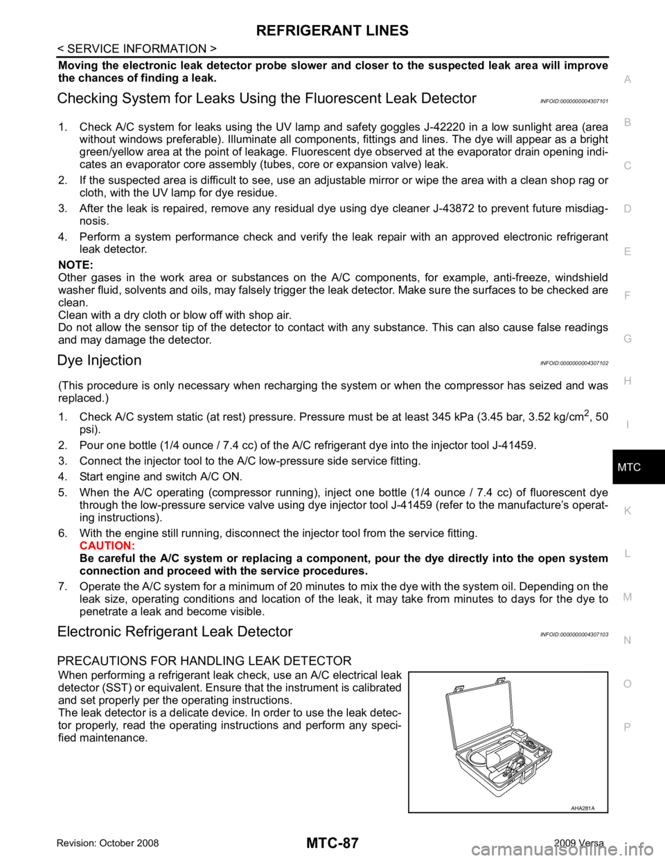
PRECAUTIONS FOR HANDLING LEAK DETECTOR When performing a refrigerant leak c heck, use an A/C electrical leak
detector (SST) or equivalent. Ensure that the instrument is calibrated
and set properly per the operating instructions.
The leak detector is a delicate device. In order to use the leak detec-
tor properly, read the operating instructions and perform any speci-
fied maintenance. AHA281A
Page 3973 of 4331
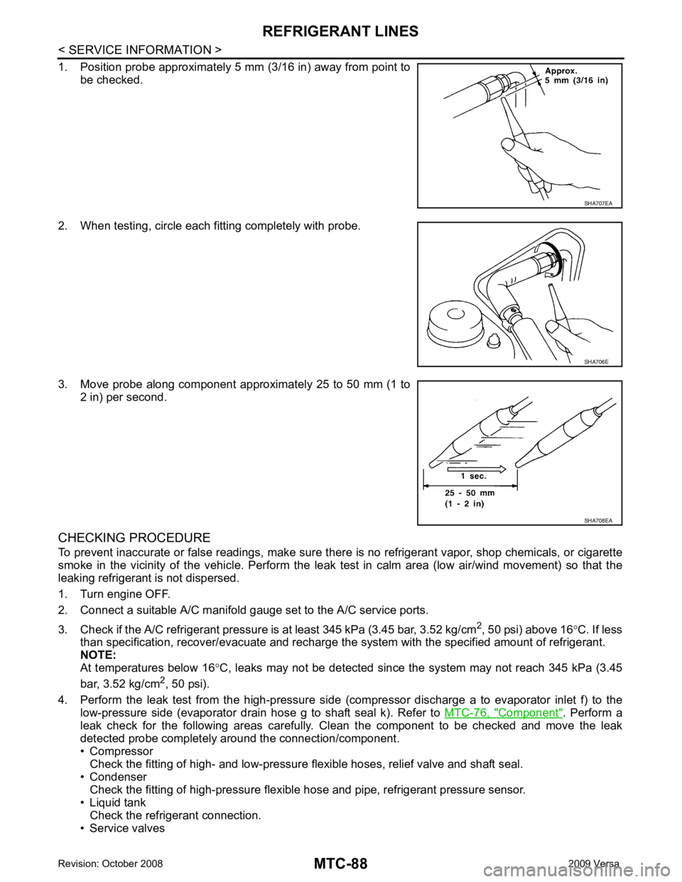
Component " . Perform a
leak check for the following areas carefully. Clean the component to be checked and move the leak
detected probe completely around the connection/component.
• Compressor
Check the fitting of high- and low-pressure flexible hoses, relief valve and shaft seal.
• Condenser
Check the fitting of high-pressure flexible hose and pipe, refrigerant pressure sensor.
• Liquid tank Check the refrigerant connection.
• Service valves SHA706E
SHA708EA
Page 4028 of 4331
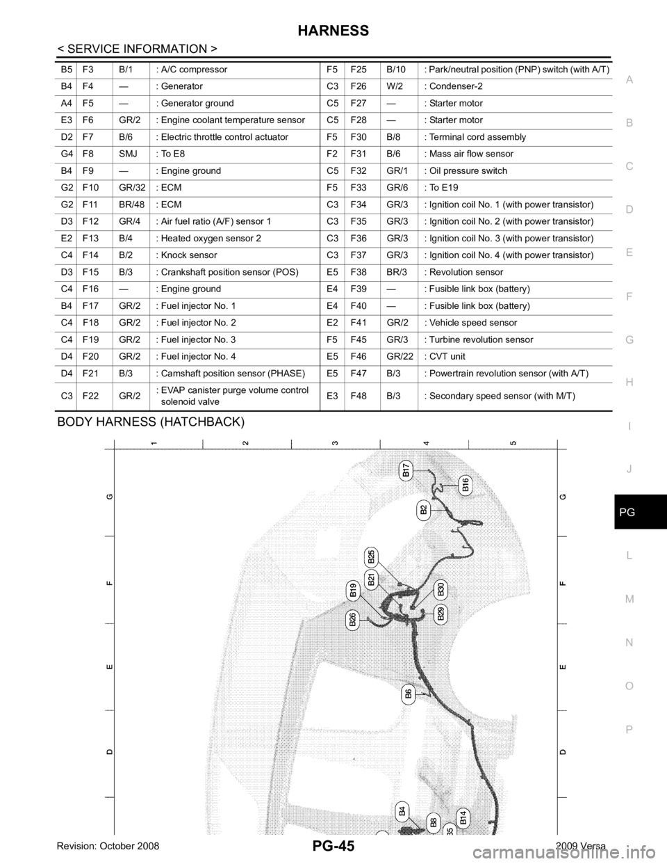
PG
N
O P
BODY HARNESS (HATCHBACK) B5 F3 B/1 : A/C compressor F5 F25 B/10 : Park/n
eutral position (PNP) switch (with A/T)
B4 F4 — : Generator C3 F26 W/2 : Condenser-2
A4 F5 — : Generator ground C5 F27 — : Starter motor
E3 F6 GR/2 : Engine coolant temperature sensor C5 F28 — : Starter motor
D2 F7 B/6 : Electric throttle control actuator F5 F30 B/8 : Terminal cord assembly
G4 F8 SMJ : To E8 F2 F31 B/6 : Mass air flow sensor
B4 F9 — : Engine ground C5 F32 GR/1 : Oil pressure switch
G2 F10 GR/32 : ECM F5 F33 GR/6 : To E19
G2 F11 BR/48 : ECM C3 F34 GR/3 : Ignition coil No. 1 (with power transistor)
D3 F12 GR/4 : Air fuel ratio (A/F) sensor 1 C3 F35 GR/3 : Ignition coil No. 2 (with power transistor)
E2 F13 B/4 : Heated oxygen sensor 2 C3 F36 GR/3 : Ignition coil No. 3 (with power transistor)
C4 F14 B/2 : Knock sensor C3 F37 GR/3 : Ignition coil No. 4 (with power transistor)
D3 F15 B/3 : Crankshaft position sensor (POS) E5 F38 BR/3 : Revolution sensor
C4 F16 — : Engine ground E4 F39 — : Fusible link box (battery)
B4 F17 GR/2 : Fuel injector No. 1 E4 F40 — : Fusible link box (battery)
C4 F18 GR/2 : Fuel injector No. 2 E2 F41 GR/2 : Vehicle speed sensor
C4 F19 GR/2 : Fuel injector No. 3 F5 F45 GR/3 : Turbine revolution sensor
D4 F20 GR/2 : Fuel injector No. 4 E5 F46 GR/22 : CVT unit
D4 F21 B/3 : Camshaft position sensor (PHASE) E5 F4 7 B/3 : Powertrain revolution sensor (with A/T)
C3 F22 GR/2 : EVAP canister purge volume control
solenoid valve E3 F48 B/3 : Secondary speed sensor (with M/T)