NISSAN LATIO 2009 Service Repair Manual
Manufacturer: NISSAN, Model Year: 2009, Model line: LATIO, Model: NISSAN LATIO 2009Pages: 4331, PDF Size: 58.04 MB
Page 1631 of 4331
![NISSAN LATIO 2009 Service Repair Manual P0420 THREE WAY CATALYST FUNCTION
EC-275
< COMPONENT DIAGNOSIS >
[HR16DE] C
D E
F
G H
I
J
K L
M A EC
NP
O
Diagnosis Procedure
INFOID:00000000047801681.
CHECK EXHAUST SYSTEM
Visually check exhaust tube NISSAN LATIO 2009 Service Repair Manual P0420 THREE WAY CATALYST FUNCTION
EC-275
< COMPONENT DIAGNOSIS >
[HR16DE] C
D E
F
G H
I
J
K L
M A EC
NP
O
Diagnosis Procedure
INFOID:00000000047801681.
CHECK EXHAUST SYSTEM
Visually check exhaust tube](/img/5/57359/w960_57359-1630.png)
P0420 THREE WAY CATALYST FUNCTION
EC-275
< COMPONENT DIAGNOSIS >
[HR16DE] C
D E
F
G H
I
J
K L
M A EC
NP
O
Diagnosis Procedure
INFOID:00000000047801681.
CHECK EXHAUST SYSTEM
Visually check exhaust tubes and muffler for dent.
Is the inspection result normal? YES >> GO TO 2.
NO >> Repair or replace. 2.
CHECK EXHAUST GAS LEAK
1. Start engine and run it at idle.
2. Listen for an exhaust gas leak before the three way catalyst (manifold).
Is exhaust gas leak detected? YES >> Repair or replace.
NO >> GO TO 3. 3.
CHECK INTAKE AIR LEAK
Listen for an intake air leak after the mass air flow sensor.
Is intake air leak detected? YES >> Repair or replace.
NO >> GO TO 4. 4.
CHECK IDLE SPEED AND IGNITION TIMING
For procedure, refer to EC-30, " IGNITION TIMING : Special Repair Requirement " .
For specification, refer to EC-504, " Idle Speed " and
EC-504, " Ignition Timing " .
Is the inspection result normal? YES >> GO TO 5.
NO >> Follow the instruction of EC-26, " BASIC INSPECTION : Special Repair Requirement " .
5.
CHECK FUEL INJECTOR
1. Stop engine and then turn ignition switch ON.
2. Check the voltage between ECM harness connector and ground.
Is the inspection result normal? YES >> GO TO 6.
NO >> Perform EC-431, " Diagnosis Procedure " .
6.
CHECK FUNCTION OF IGNITION COIL-I
CAUTION: PBIB1216E
ECM
Ground Voltage
Connector Terminal
F10 25
Ground Battery voltage
29
30
31 JMBIA2201GB
Page 1632 of 4331
![NISSAN LATIO 2009 Service Repair Manual EC-276< COMPONENT DIAGNOSIS >
[HR16DE]
P0420 THREE WAY CATALYST FUNCTION
Do the following procedure in the place where ventilation is good without the combustible.
1. Turn ignition switch OFF.
2. Rem NISSAN LATIO 2009 Service Repair Manual EC-276< COMPONENT DIAGNOSIS >
[HR16DE]
P0420 THREE WAY CATALYST FUNCTION
Do the following procedure in the place where ventilation is good without the combustible.
1. Turn ignition switch OFF.
2. Rem](/img/5/57359/w960_57359-1631.png)
EC-276< COMPONENT DIAGNOSIS >
[HR16DE]
P0420 THREE WAY CATALYST FUNCTION
Do the following procedure in the place where ventilation is good without the combustible.
1. Turn ignition switch OFF.
2. Remove fuel pump fuse in IPDM E/R to release fuel pressure.
NOTE:
Do not use CONSULT-III to release fuel pressure, or fuel pressure applies again during the following pro-
cedure.
3. Start engine.
4. After engine stalls, crank it two or three times to release all fuel pressure.
5. Turn ignition switch OFF.
6. Remove all ignition coil harness connectors to avoi d the electrical discharge from the ignition coils.
7. Remove ignition coil and spark plug of the cylinder to be checked.
8. Crank engine for 5 seconds or more to remove combustion gas in the cylinder.
9. Connect spark plug and harness connector to ignition coil.
10. Fix ignition coil using a rope etc. with gap of 13 - 17 mm (0.52 - 0.66 in) between the edge of the spark plug and grounded metal
portion as shown in the figure.
11. Crank engine for about 3 seconds, and check whether spark is
generated between the spark plug and the grounded metal por-
tion.
CAUTION:
• During the operation, always stay 0.5 m (19.7 in) away from the spark plug and the ig nition coil. Be careful not to
get an electrical shock wh ile checking, because the elec-
trical discharge voltage becomes 20 kV or more.
• It might cause to damage the igni tion coil if the gap of more than 17 mm (0.66 in) is taken.
NOTE:
When the gap is less than 13 mm (0.52 in), the sp ark might be generated even if the coil is mal-
functioning.
Is the inspection result normal? YES >> GO TO 10.
NO >> GO TO 7. 7.
CHECK FUNCTION OF IGNITION COIL-II
1. Turn ignition switch OFF.
2. Disconnect spark plug and connect a known-good spark plug.
3. Crank engine for about 3 seconds, and recheck whether spark is generated between the spark plug and
the grounded metal portion.
Is the inspection result normal? YES >> GO TO 8.
NO >> Check ignition coil, power transistor and their circuits. Refer to EC-441, " Diagnosis Procedure " .
8.
CHECK SPARK PLUG
Check the initial spark plug for fouling, etc.
Is the inspection result normal? YES >> Replace spark plug(s) with standard type one(s). For
spark plug type, refer to EM-117, " Spark Plug " .
NO >> Repair or clean spark plug. Then GO TO 9. 9.
CHECK FUNCTION OF IGNITION COIL-III Spark should be generated. JMBIA0066GB
Spark should be generated.
SEF156I
Page 1633 of 4331
EC
NP
O
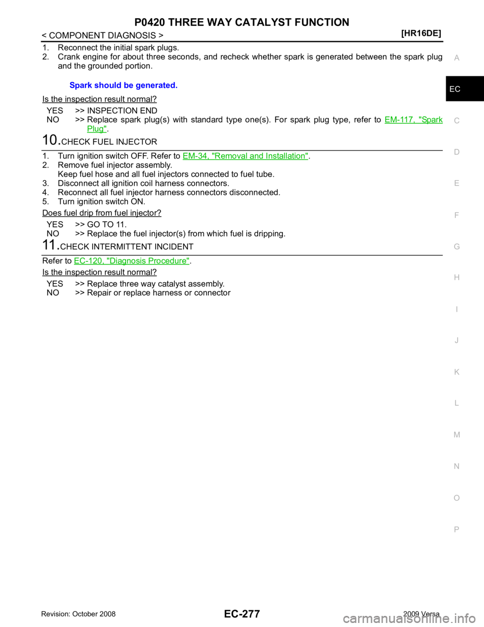
1. Reconnect the initial spark plugs.
2. Crank engine for about three seconds, and recheck whether spark is generated between the spark plug and the grounded portion.
Is the inspection result normal? YES >> INSPECTION END
NO >> Replace spark plug(s) with standard type one(s). For spark plug type, refer to EM-117, " Spark
Plug " .
Removal and Installation " .
2. Remove fuel injector assembly. Keep fuel hose and all fuel injectors connected to fuel tube.
3. Disconnect all ignition coil harness connectors.
4. Reconnect all fuel injector harness connectors disconnected.
5. Turn ignition switch ON.
Does fuel drip from fuel injector? YES >> GO TO 11.
NO >> Replace the fuel injector(s) from which fuel is dripping. Diagnosis Procedure " .
Is the inspection result normal? YES >> Replace three way catalyst assembly.
NO >> Repair or replace harness or connector Spark should be generated.
Page 1634 of 4331
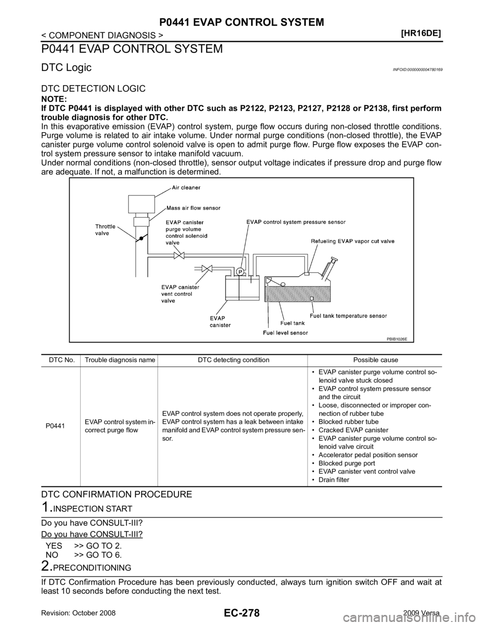
YES >> GO TO 2.
NO >> GO TO 6.
Page 1635 of 4331
EC
NP
O
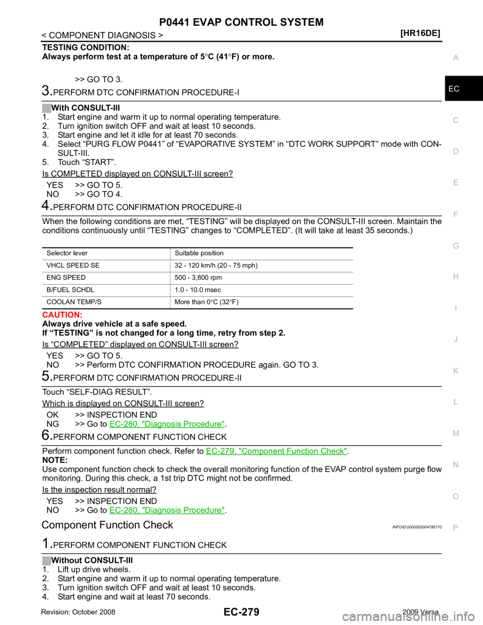
TESTING CONDITION:
Always perform test at a temperature of 5 °C (41 °F) or more.
>> GO TO 3. YES >> GO TO 5.
NO >> GO TO 4. “ COMPLETED ” displayed on CONSULT-III screen?
YES >> GO TO 5.
NO >> Perform DTC CONFIRMATION PROCEDURE again. GO TO 3. OK >> INSPECTION END
NG >> Go to EC-280, " Diagnosis Procedure " .
Component Function Check " .
NOTE:
Use component function check to check the overall m onitoring function of the EVAP control system purge flow
monitoring. During this check, a 1s t trip DTC might not be confirmed.
Is the inspection result normal? YES >> INSPECTION END
NO >> Go to EC-280, " Diagnosis Procedure " .
Component Function Check INFOID:0000000004780170
Page 1636 of 4331
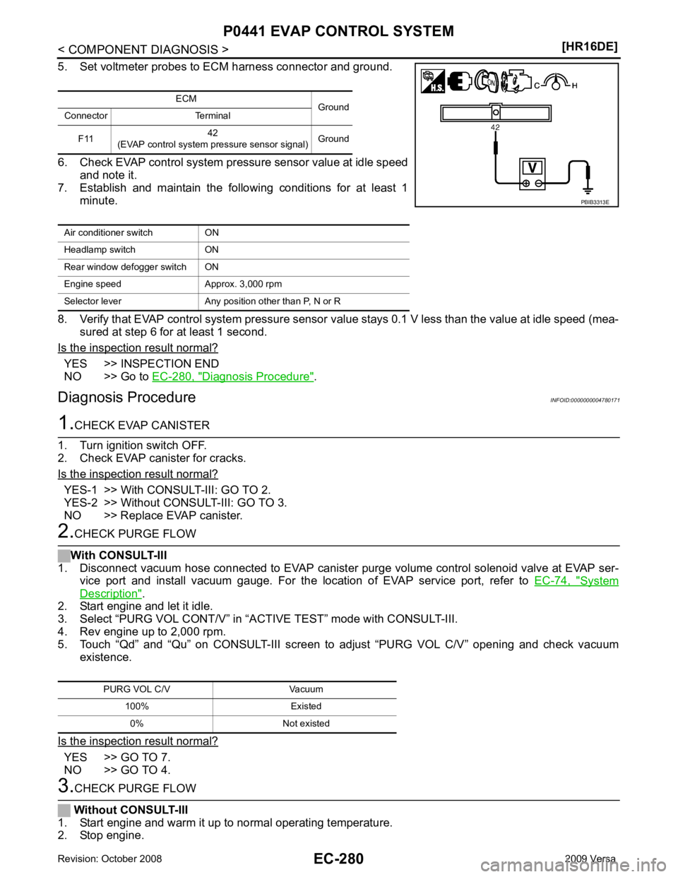
YES >> INSPECTION END
NO >> Go to EC-280, " Diagnosis Procedure " .
Diagnosis Procedure INFOID:0000000004780171YES-1 >> With CONSULT-III: GO TO 2.
YES-2 >> Without CONSULT-III: GO TO 3.
NO >> Replace EVAP canister. System
Description " .
2. Start engine and let it idle.
3. Select “PURG VOL CONT/V” in “A CTIVE TEST” mode with CONSULT-III.
4. Rev engine up to 2,000 rpm.
5. Touch “Qd” and “Qu” on CONSULT-III screen to adjust “PURG VOL C/V” opening and check vacuum
existence.
Is the inspection result normal? YES >> GO TO 7.
NO >> GO TO 4.
Page 1637 of 4331
EC
NP
O
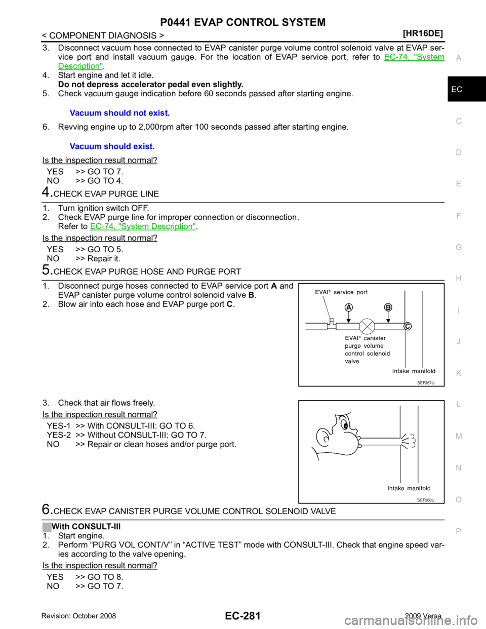
3. Disconnect vacuum hose connected to EVAP canister
purge volume control solenoid valve at EVAP ser-
vice port and install vacuum gauge. For the location of EVAP service port, refer to EC-74, " System
Description " .
4. Start engine and let it idle.
Do not depress accelerator pedal even slightly.
5. Check vacuum gauge indication before 60 seconds passed after starting engine.
6. Revving engine up to 2,000rpm after 100 seconds passed after starting engine.
Is the inspection result normal? YES >> GO TO 7.
NO >> GO TO 4. System Description " .
Is the inspection result normal? YES >> GO TO 5.
NO >> Repair it. YES-1 >> With CONSULT-III: GO TO 6.
YES-2 >> Without CONSULT-III: GO TO 7.
NO >> Repair or clean hoses and/or purge port. YES >> GO TO 8.
NO >> GO TO 7. Vacuum should not exist.
Vacuum should exist. SEF368U
Page 1638 of 4331
Component Inspection " .
Is the inspection result normal? YES >> GO TO 8.
NO >> Replace EVAP canister purge volume control solenoid valve. YES >> GO TO 9.
NO >> Replace EVAP control system pressure sensor. DTC Logic " for DTC P0452,
EC-322, " DTC Logic " for DTC P0453.
Is the inspection result normal? YES >> GO TO 10.
NO >> Replace EVAP control system pressure sensor. YES >> GO TO 11.
NO >> Clean the rubber tube using an air blower. Component Inspection (Drain filter) " .
Is the inspection result normal? YES >> GO TO 12.
NO >> Replace drain filter. Component Inspection " .
Is the inspection result normal? YES >> GO TO 13.
NO >> Replace EVAP canister vent control valve. Inspection " .
Is the inspection result normal? YES >> GO TO 14.
NO >> Replace it. Diagnosis Procedure " .
Water should not exist.
Page 1639 of 4331
EC
NP
O
>> INSPECTION END
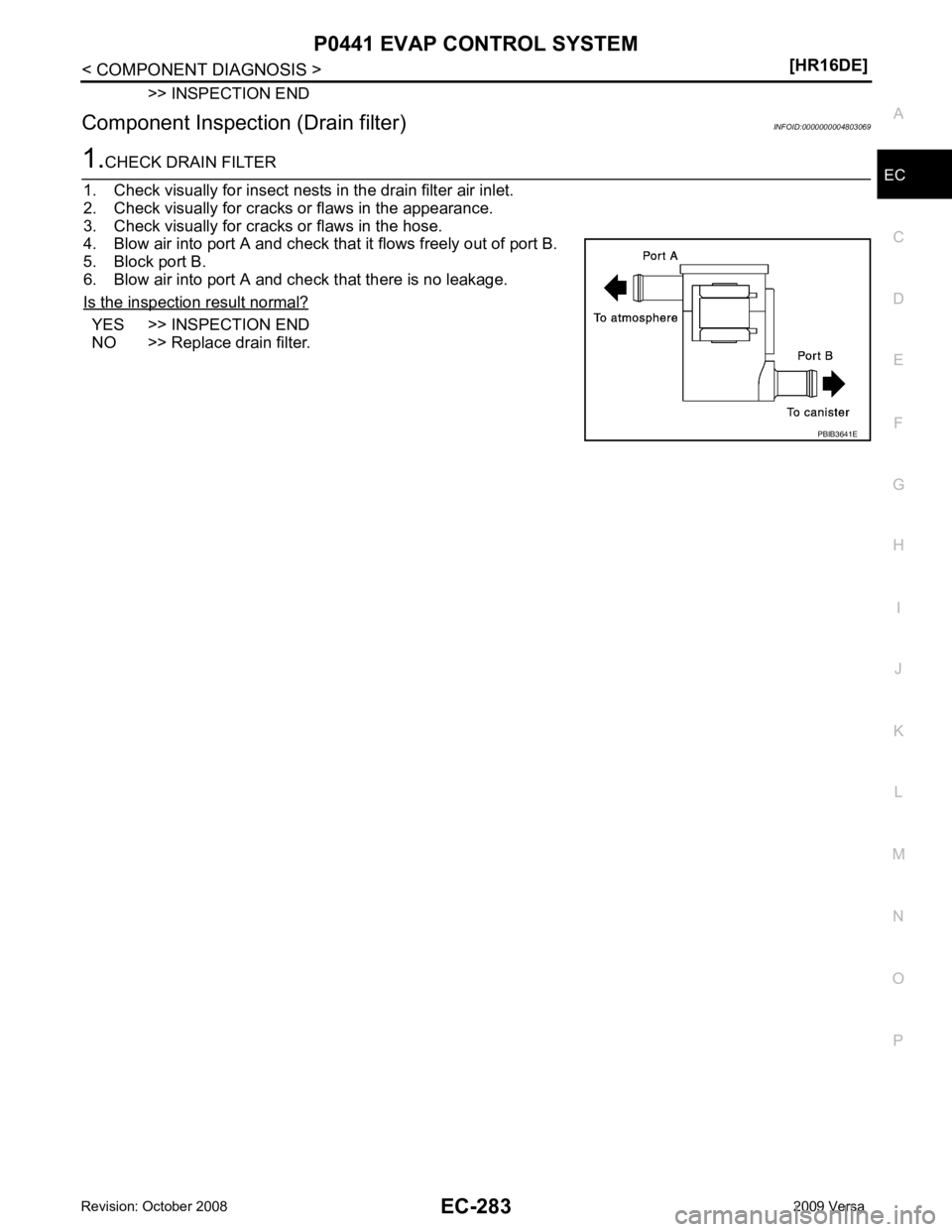
Component Inspection (Drain filter) INFOID:0000000004803069YES >> INSPECTION END
NO >> Replace drain filter.
Page 1640 of 4331
![NISSAN LATIO 2009 Service Repair Manual EC-284< COMPONENT DIAGNOSIS >
[HR16DE]
P0442 EVAP CONTROL SYSTEM
P0442 EVAP CONTROL SYSTEM
DTC Logic INFOID:0000000004780172
DTC DETECTION LOGIC
NOTE:
If DTC P0442 is displayed with DTC P0456, first p NISSAN LATIO 2009 Service Repair Manual EC-284< COMPONENT DIAGNOSIS >
[HR16DE]
P0442 EVAP CONTROL SYSTEM
P0442 EVAP CONTROL SYSTEM
DTC Logic INFOID:0000000004780172
DTC DETECTION LOGIC
NOTE:
If DTC P0442 is displayed with DTC P0456, first p](/img/5/57359/w960_57359-1639.png)
EC-284< COMPONENT DIAGNOSIS >
[HR16DE]
P0442 EVAP CONTROL SYSTEM
P0442 EVAP CONTROL SYSTEM
DTC Logic INFOID:0000000004780172
DTC DETECTION LOGIC
NOTE:
If DTC P0442 is displayed with DTC P0456, first pe rform the trouble diagnosis for DTC P0456. Refer to
EC-335, " DTC Logic " .
This diagnosis detects leaks in the EVAP purge line using engine intake manifold vacuum.
If pressure does not increase, the ECM will check for l eaks in the line between the fuel tank and EVAP canister
purge volume control solenoid valve, under the following “Vacuum test” conditions.
The EVAP canister vent control valve is closed to s hut the EVAP purge line off. The EVAP canister purge vol-
ume control solenoid valve will then be opened to depressurize the EVAP purge line using intake manifold
vacuum. After this occurs, the EVAP canister purge volume control solenoid valve will be closed.
CAUTION:
• Use only a genuine NISSAN fuel filler cap as a replacemen t. If an incorrect fuel filler cap is used, the
MIL may come on. DTC No. Trouble diagnosis name DTC detecting condition Possible cause
P0442 EVAP control system
small leak detected
(negative pressure) EVAP control system has a leak, EVAP
control system does not operate prop-
erly. • Incorrect fuel tank vacuum relief valve
• Incorrect fuel filler cap used
• Fuel filler cap remains open or fails to close.
• Foreign matter caught in fuel filler cap.
• Leak is in line between intake manifold and EVAP
canister purge volume control solenoid valve.
• Foreign matter caught in EVAP canister vent con- trol valve.
• EVAP canister or fuel tank leaks
• EVAP purge line (pipe and rubber tube) leaks
• EVAP purge line rubber tube bent
• Loose or disconnected rubber tube
• EVAP canister vent control valve and the circuit
• EVAP canister purge volume control solenoid
valve and the circuit
• Fuel tank temperature sensor
• O-ring of EVAP canister vent control valve is
missing or damaged
• EVAP canister is saturated with water
• EVAP control system pressure sensor
• Fuel level sensor and the circuit
• Refueling EVAP vapor cut valve
• ORVR system leaks
• Drain filter PBIB1026E