NISSAN LATIO 2009 Service Repair Manual
Manufacturer: NISSAN, Model Year: 2009, Model line: LATIO, Model: NISSAN LATIO 2009Pages: 4331, PDF Size: 58.04 MB
Page 3011 of 4331
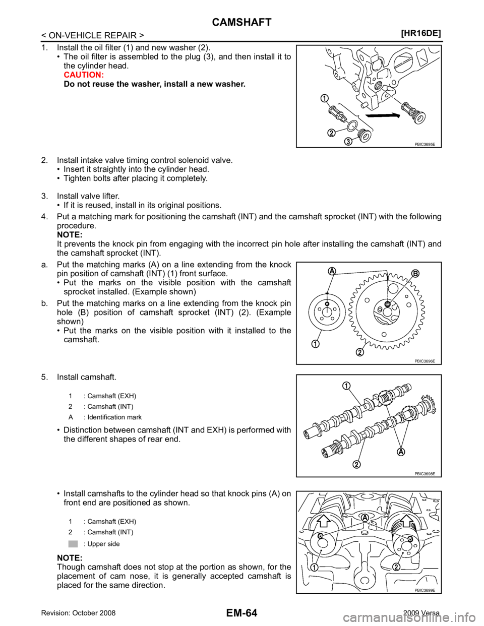
PBIC3696E
Page 3012 of 4331
EM
NP
O
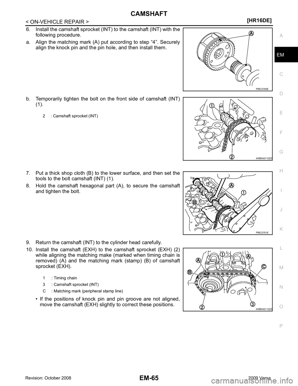
6. Install the camshaft sprocket (INT) to the camshaft (INT) with the
following procedure.
a. Align the matching mark (A) put according to step “4”. Securely align the knock pin and the pin hole, and then install them.
b. Temporarily tighten the bolt on the front side of camshaft (INT) (1).
7. Put a thick shop cloth (B) to the lower surface, and then set the tools to the bolt camshaft (INT) (1).
8. Hold the camshaft hexagonal part (A), to secure the camshaft and tighten the bolt.
9. Return the camshaft (INT) to the cylinder head carefully.
10. Install the camshaft (EXH) to the camshaft sprocket (EXH) (2) while aligning the matching make (marked when timing chain is
removed) (A) and the matching mark (stamp) (B) of camshaft
sprocket (EXH).
• If the positions of knock pin and pin groove are not aligned, move the camshaft (EXH) slightly to correct these positions. PBIC3701E
Page 3013 of 4331
![NISSAN LATIO 2009 Service Repair Manual EM-66< ON-VEHICLE REPAIR >
[HR16DE]
CAMSHAFT
11. Hold the camshaft hexagonal part (A), to secure the camshaft and tighten the bolt.
CAUTION:
• Make sure that the matching mark (marked NISSAN LATIO 2009 Service Repair Manual EM-66< ON-VEHICLE REPAIR >
[HR16DE]
CAMSHAFT
11. Hold the camshaft hexagonal part (A), to secure the camshaft and tighten the bolt.
CAUTION:
• Make sure that the matching mark (marked](/img/5/57359/w960_57359-3012.png)
EM-66< ON-VEHICLE REPAIR >
[HR16DE]
CAMSHAFT
11. Hold the camshaft hexagonal part (A), to secure the camshaft and tighten the bolt.
CAUTION:
• Make sure that the matching mark (marked when timing chain is removed) and each camshaft sprocket matching
mark are in the correct location.
12. Install camshaft brackets (No. 2 to 5) aligning the identification marks on upper surface as shown.
• Install so that identification mark can be correctly read when viewed from the INT side.
13. Tighten bolts of camshaft brackets in the following steps, in numerical order as shown.
a. Tighten No. 9 to 11 in numerical order.
b. Tighten No. 1 to 8 in numerical order.
c. Tighten all bolts in numerical order.
d. Tighten all bolts in numerical order. 1 : Camshaft sprocket (EXH) AWBIA0102ZZ
A : EXH side
B : INT side
: Engine front PBIC3703E
A : EXH side
B : INT side
: Engine front
Camshaft bracket bolts (9 - 11) : 1.96 N·m (0.20 kg-m, 17 in-lb)
Camshaft bracket bolts (1 - 8) : 1.96 N·m (0.20 kg-m, 17 in-lb)
Camshaft bracket bolts (all) : 5.88 N·m (0.60 kg-m, 52 in-lb)
Camshaft bracket bolts (all) : 10.4 N·m (1.1 kg-m, 8 ft-lb) PBIC3686E
Page 3014 of 4331
![NISSAN LATIO 2009 Service Repair Manual CAMSHAFT
EM-67
< ON-VEHICLE REPAIR >
[HR16DE] C
D E
F
G H
I
J
K L
M A EM
NP
O
14. Install timing chain with the following procedure.
• Install by aligning matching marks on each sprocket and NISSAN LATIO 2009 Service Repair Manual CAMSHAFT
EM-67
< ON-VEHICLE REPAIR >
[HR16DE] C
D E
F
G H
I
J
K L
M A EM
NP
O
14. Install timing chain with the following procedure.
• Install by aligning matching marks on each sprocket and](/img/5/57359/w960_57359-3013.png)
CAMSHAFT
EM-67
< ON-VEHICLE REPAIR >
[HR16DE] C
D E
F
G H
I
J
K L
M A EM
NP
O
14. Install timing chain with the following procedure.
• Install by aligning matching marks on each sprocket and tim-ing chain.
• If these matching marks are not aligned, rotate the camshaft
slightly to correct the position.
CAUTION:
• Check matching mark positi on of each sprocket and tim-
ing chain again after instal ling the timing chain, keep
matching marks aligned by holding them with a hand.
• To avoid skipped teeth, never rotate crankshaft and cam-
shaft until front cover is installed.
15. Install timing chain tension guide (2) and timing chain slack guide (1).
16. Install chain tensioner (1). • Fix the plunger at the most compressed position using a stop-per pin (A), and then install it.
• Securely pull out the stopper pin after installing the chain ten-
sioner.
17. Check matching mark position of timing chain and each sprocket again. A : Dark blue link
B : Matching mark (stamp)
C : Orange link
D : Matching mark (stamp)
E : Crankshaft key (point straight up)
F : Matching mark (peripheral stamp line)
G : Dark blue link PBIC3721E
PBIC3714E
PBIC3722E
Page 3015 of 4331
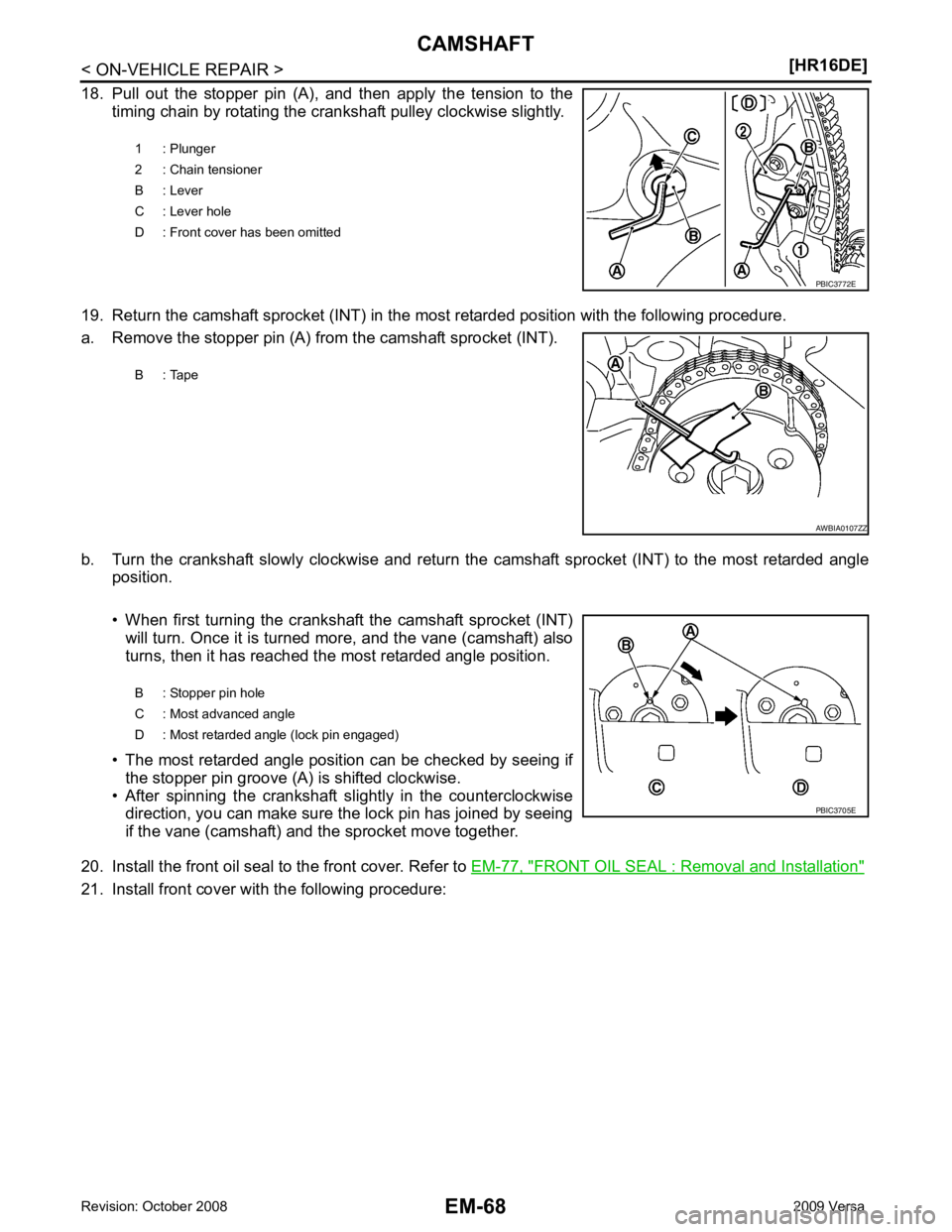
FRONT OIL SEAL : Removal and Installation "
21. Install front cover with the following procedure:1 : Plunger
2 : Chain tensioner
B : Lever
C : Lever hole
D : Front cover has been omitted
Page 3016 of 4331
![NISSAN LATIO 2009 Service Repair Manual CAMSHAFT
EM-69
< ON-VEHICLE REPAIR >
[HR16DE] C
D E
F
G H
I
J
K L
M A EM
NP
O
a. Apply a continuous bead of liquid gasket with Tool to front cover
as shown.
Use Genuine Silicone RTV Seal ant or NISSAN LATIO 2009 Service Repair Manual CAMSHAFT
EM-69
< ON-VEHICLE REPAIR >
[HR16DE] C
D E
F
G H
I
J
K L
M A EM
NP
O
a. Apply a continuous bead of liquid gasket with Tool to front cover
as shown.
Use Genuine Silicone RTV Seal ant or](/img/5/57359/w960_57359-3015.png)
CAMSHAFT
EM-69
< ON-VEHICLE REPAIR >
[HR16DE] C
D E
F
G H
I
J
K L
M A EM
NP
O
a. Apply a continuous bead of liquid gasket with Tool to front cover
as shown.
Use Genuine Silicone RTV Seal ant or equivalent. Refer to
GI-42, " Recommended Chemical Product and Sealant " .
b. Apply a continuous bead of liquid gasket with Tool to front cover as shown.
Use Genuine Silicone RT V Sealant or equivalent. Refer to
GI-42, " Recommended Chemical Product and Sealant " .
1 : Cylinder head
2 : Cylinder block
3 : Oil pan (upper)
A : Liquid gasket application φ 3.0 - 4.0 mm (0.12 - 0.16 in) dia.
Tool number : WS39930000 ( — ) PBIC3724E
A : Liquid gasket application
φ 3.0 - 4.0 mm (0.12 - 0.16 in) dia.
Tool number : WS39930000 ( — ) PBIC3725E
Page 3017 of 4331
![NISSAN LATIO 2009 Service Repair Manual EM-70< ON-VEHICLE REPAIR >
[HR16DE]
CAMSHAFT
c. Tighten bolts in the numerical order shown.
d. After all bolts are tightened, retighten them to specified torque in numerical order as shown.
CAUTION:
B NISSAN LATIO 2009 Service Repair Manual EM-70< ON-VEHICLE REPAIR >
[HR16DE]
CAMSHAFT
c. Tighten bolts in the numerical order shown.
d. After all bolts are tightened, retighten them to specified torque in numerical order as shown.
CAUTION:
B](/img/5/57359/w960_57359-3016.png)
EM-70< ON-VEHICLE REPAIR >
[HR16DE]
CAMSHAFT
c. Tighten bolts in the numerical order shown.
d. After all bolts are tightened, retighten them to specified torque in numerical order as shown.
CAUTION:
Be sure to wipe off any excessive liquid gasket leaking to
surface.
22. Insert crankshaft pulley by aligning with crankshaft key. • When inserting crankshaft pulley with a plastic hamme r, tap on its center portion (not circumference).
CAUTION:
Never damage front oil seal lip section.
23. Tighten crankshaft pulley bolt with the following procedure: • Secure crankshaft pulley with a suitable tool, and tighten crankshaft pulley bolt.
a. Apply new engine oil to thread and seat surfaces of crankshaft pulley bolt.
b. Tighten crankshaft pulley bolt.
c. Put a paint mark (B) on crankshaft pulley, mating with any one of six easy to recognize angle marks (A) on crankshaft bolt flange
(1).
d. Turn another 60 degrees clockwise (angle tightening). • Check the tightening angle with movement of one angle mark.
24. Make sure that crankshaft turns smoothly by rotating by hand clockwise.
25. Install the camshaft position sensor (PHASE) to the rear end of cylinder head.
• Tighten bolts with it seated completely.
26. Check and adjust valve clearance. Refer to EM-20, " Inspection and Adjustment " .
27. Installation of the remaining components is in the reverse order of removal.
Inspection INFOID:0000000004784301
INSPECTION AFTER REMOVAL
Oil Filter KBIA3429J
Crankshaft pulley bolt : 35.0 N·m (3.6 kg-m, 26 ft-lb)
PBIC3726E
Page 3018 of 4331
EM
NP
O
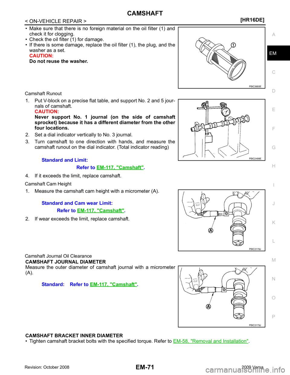
• Make sure that there is no foreign material on the oil filter (1) and
check it for clogging.
• Check the oil filter (1) for damage.
• If there is some damage, replace t he oil filter (1), the plug, and the
washer as a set.
CAUTION:
Do not reuse the washer.
Camshaft Runout 1. Put V-block on a precise flat table, and support No. 2 and 5 jour- nals of camshaft.
CAUTION:
Never support No. 1 journal (on the side of camshaft
sprocket) because it has a different diameter from the other
four locations.
2. Set a dial indicator vertically to No. 3 journal.
3. Turn camshaft to one direction with hands, and measure the camshaft runout on the dial indicator. (Total indicator reading)
4. If it exceeds the limit, replace camshaft.
Camshaft Cam Height 1. Measure the camshaft cam height with a micrometer (A).
2. If wear exceeds the limit, replace camshaft.
Camshaft Journa l Oil Clearance
CAMSHAFT JOURNAL DIAMETER
Measure the outer diameter of camshaft journal with a micrometer
(A).
CAMSHAFT BRACKET INNER DIAMETER
• Tighten camshaft bracket bolts with the specified torque. Refer to EM-58, " Removal and Installation " .Camshaft " .
Camshaft " .
Camshaft " .
Page 3019 of 4331
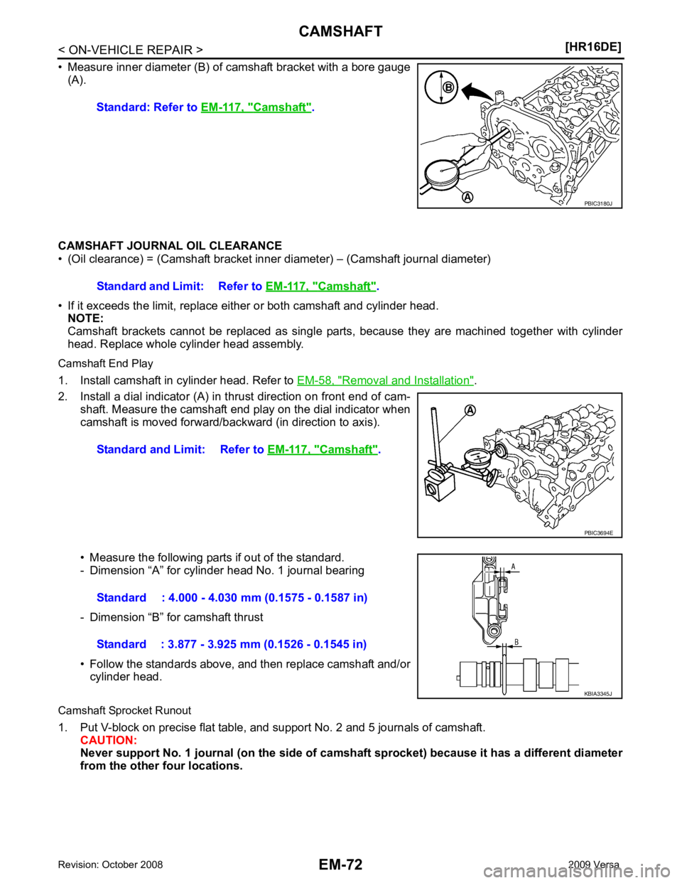
Removal and Installation " .
2. Install a dial indicator (A) in thrust direction on front end of cam- shaft. Measure the camshaft end play on the dial indicator when
camshaft is moved forward/backward (in direction to axis).
• Measure the following parts if out of the standard.
- Dimension “A” for cylinder head No. 1 journal bearing
- Dimension “B” for camshaft thrust
• Follow the standards above, and then replace camshaft and/or cylinder head.
Camshaft Sprocket Runout
1. Put V-block on precise flat table, and support No. 2 and 5 journals of camshaft. CAUTION:
Never support No. 1 journal (on the side of cam shaft sprocket) because it has a different diameter
from the other four locations. Standard: Refer to
EM-117, " Camshaft " .
Camshaft " .
Standard and Limit: Refer to EM-117, " Camshaft " .
Page 3020 of 4331
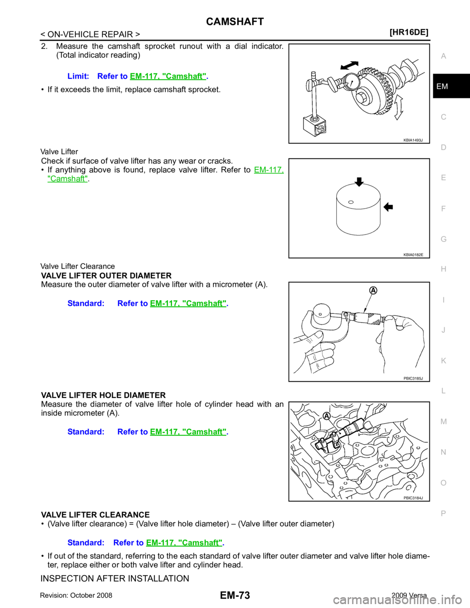
EM
NP
O
2. Measure the camshaft sprocket runout with a dial indicator.
(Total indicator reading)
• If it exceeds the limit, replace camshaft sprocket.
Valve Lifter Check if surface of valve lifter has any wear or cracks.
• If anything above is found, replace valve lifter. Refer to EM-117," Camshaft " .
Valve Lifter Clearance VALVE LIFTER OUTER DIAMETER
Measure the outer diameter of va lve lifter with a micrometer (A).
VALVE LIFTER HOLE DIAMETER
Measure the diameter of valve lifter hole of cylinder head with an
inside micrometer (A).
VALVE LIFTER CLEARANCE
• (Valve lifter clearance) = (Valve lifter hole diameter) – (Valve lifter outer diameter)
• If out of the standard, referring to the each standard of valve lifter outer diameter and valve lifter hole diame-
ter, replace either or both valve lifter and cylinder head.
INSPECTION AFTER INSTALLATION Limit: Refer to
EM-117, " Camshaft " .
KBIA0182E
Camshaft " .
Camshaft " .
Camshaft " .