NISSAN LATIO 2009 Service Repair Manual
Manufacturer: NISSAN, Model Year: 2009, Model line: LATIO, Model: NISSAN LATIO 2009Pages: 4331, PDF Size: 58.04 MB
Page 2991 of 4331
![NISSAN LATIO 2009 Service Repair Manual EM-44< ON-VEHICLE REPAIR >
[HR16DE]
OIL PAN (UPPER) AND OIL STRAINER
c. Apply a continuous bead of liquid gasket (D) with Tool to areas shown.
Use Genuine Silicone RTV Seal ant or equ NISSAN LATIO 2009 Service Repair Manual EM-44< ON-VEHICLE REPAIR >
[HR16DE]
OIL PAN (UPPER) AND OIL STRAINER
c. Apply a continuous bead of liquid gasket (D) with Tool to areas shown.
Use Genuine Silicone RTV Seal ant or equ](/img/5/57359/w960_57359-2990.png)
EM-44< ON-VEHICLE REPAIR >
[HR16DE]
OIL PAN (UPPER) AND OIL STRAINER
c. Apply a continuous bead of liquid gasket (D) with Tool to areas shown.
Use Genuine Silicone RTV Seal ant or equivalent. Refer to
GI-42, " Recommended Chemical
Product and Sealant " .
CAUTION:
Installation should be done within 5 minutes after coating.
d. Tighten bolts in the numerical order shown. CAUTION:
Avoid misalignment of both oil pan gasket and O-ring.
• The bolts are different according to the installation position. Follow the numbers shown.
2. Install rear oil seal with the following procedure: CAUTION:
• The installation of rear oil seal should be co mpleted within 5 minutes after installing oil pan
(upper).
• Do not touch oil seal lip.
a. Wipe off any liquid gasket protruding to the rear oil seal mounting part of oil pan (upper) and cylinder block using a spatula.
b. Apply the liquid gasket lightly to entire outside area of new rear oil seal. Use Genuine Silicone RTV Seal ant or equivalent. Refer to GI-42, " Recommended Chemical Prod-
uct and Sealant " .
c. Press-fit the rear oil seal using a drift with outer diameter 113 mm (4.45 in) and inner diameter 90 mm (3.54 in) (A). A : 2 mm (0.07 in) protruded to outside
B : 2 mm (0.07 in) protruded to rear oil seal mounting side
C : 5.5 - 7.5 mm (0.216 - 0.295 in)
E : 4.0 - 5.0 mm (0.157 - 0.196 in) dia.
: Engine front
: Engine out side
Tool number : WS39930000 ( — ) AWBIA0790ZZ
: Engine front
M8 × 179 mm (7.09 in) : No. 9, 10
M8 × 25 mm (0.98 in) : No. 3, 4, 7, 8
M8 × 90 mm (3.54 in) : No. 1, 2, 5, 6 ALBIA0627ZZ
PBIC3660E
Page 2992 of 4331
EM
NP
O
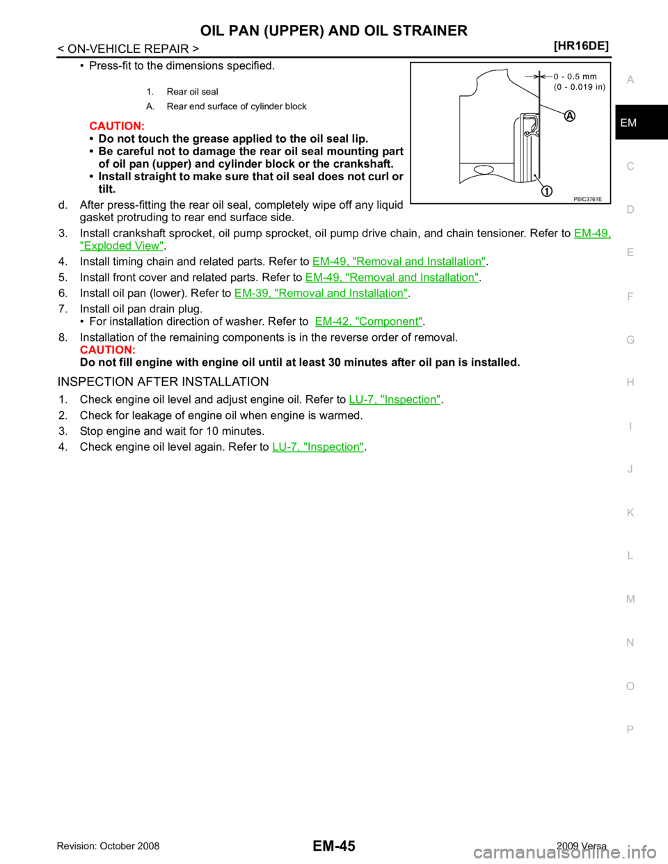
• Press-fit to the dimensions specified.
CAUTION:
• Do not touch the grease applied to the oil seal lip.
• Be careful not to damage the rear oil seal mounting part of oil pan (upper) and cylinder block or the crankshaft.
• Install straight to make sure that oil seal does not curl or tilt.
d. After press-fitting the rear oil seal, completely wipe off any liquid gasket protruding to rear end surface side.
3. Install crankshaft sprocket, oil pump sprocket, oi l pump drive chain, and chain tensioner. Refer to EM-49," Exploded View " .
4. Install timing chain and related parts. Refer to EM-49, " Removal and Installation " .
5. Install front cover and related parts. Refer to EM-49, " Removal and Installation " .
6. Install oil pan (lower). Refer to EM-39, " Removal and Installation " .
7. Install oil pan drain plug. • For installation direction of washer. Refer to EM-42, " Component " .
8. Installation of the remaining components is in the reverse order of removal. CAUTION:
Do not fill engine with engi ne oil until at least 30 minutes after oil pan is installed.
INSPECTION AFTER INSTALLATION 1. Check engine oil level and adjust engine oil. Refer to LU-7, " Inspection " .
2. Check for leakage of engine oil when engine is warmed.
3. Stop engine and wait for 10 minutes.
4. Check engine oil level again. Refer to LU-7, " Inspection " .
1. Rear oil seal
A. Rear end surface of cylinder block
Page 2993 of 4331
Exploded View " .
2. Remove ignition coil. CAUTION:
• Handle ignition coil car efully and avoid impacts.
• Never disassemble.
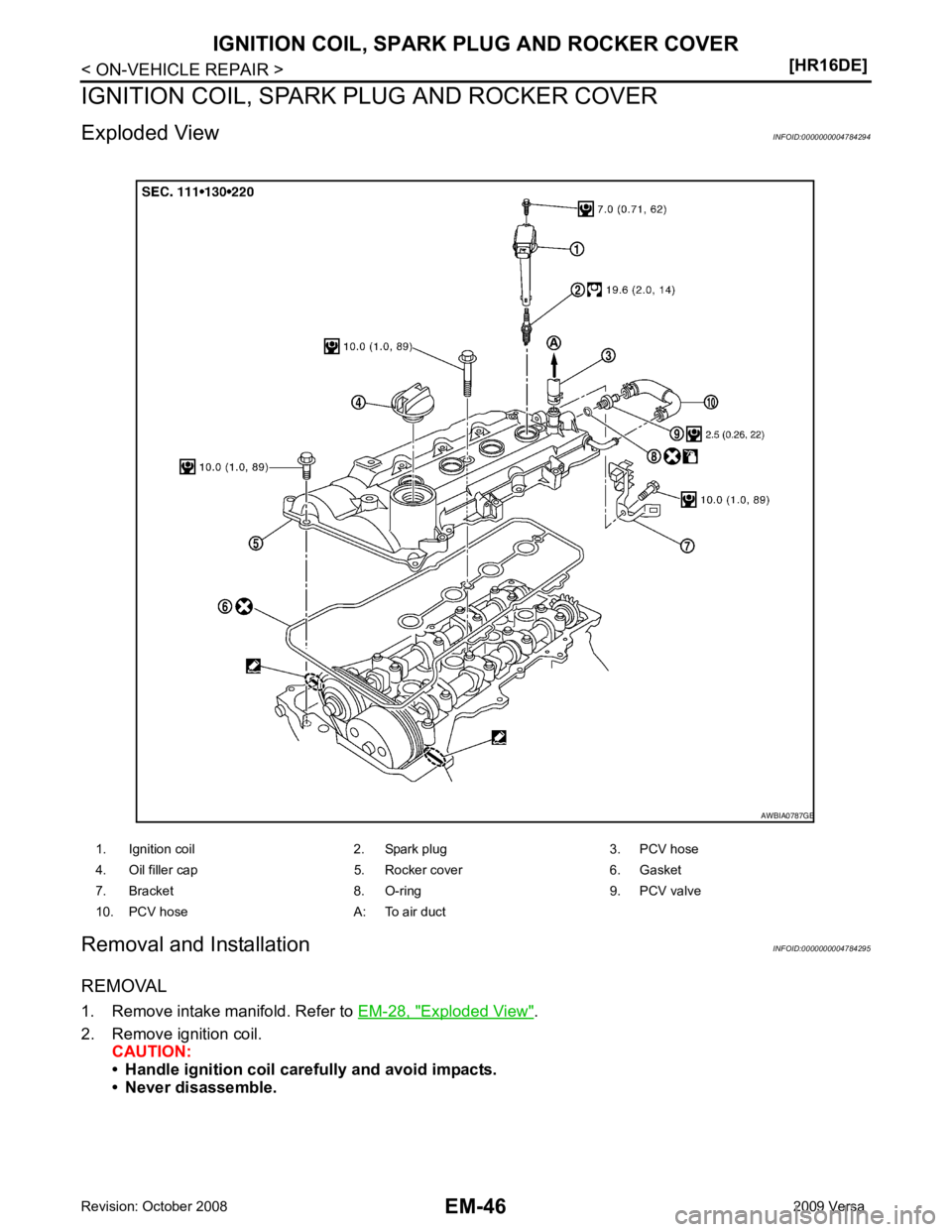
1. Ignition coil 2. Spark plug 3. PCV hose
4. Oil filler cap 5. Rocker cover 6. Gasket
7. Bracket 8. O-ring 9. PCV valve
10. PCV hose A: To air duct
Page 2994 of 4331
EM
NP
O
3. Remove spark plug using suitable tool.
CAUTION:
Never drop or shock it.
4. Remove ground cable (RH).
5. Support the bottom surface of engine using a trans mission jack, and then remove the engine mounting
bracket and insulator (RH). Refer to EM-88, " Exploded View " .
6. Remove fuel tube protector.
7. Disconnect PCV valve hose from PCV valve.
8. Remove oil filler cap.
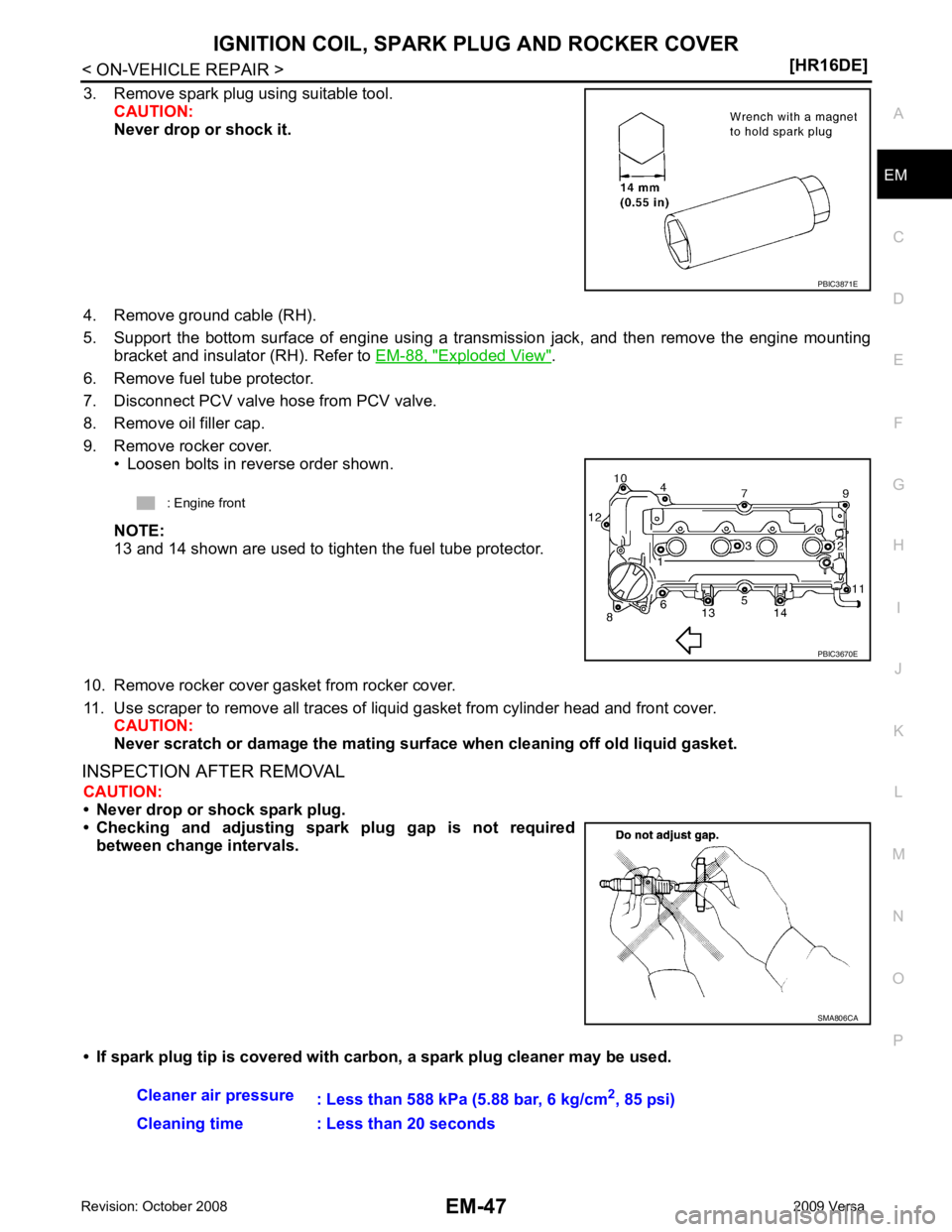
9. Remove rocker cover. • Loosen bolts in reverse order shown.
NOTE:
13 and 14 shown are used to tighten the fuel tube protector.
10. Remove rocker cover gasket from rocker cover.
11. Use scraper to remove all traces of liquid gasket from cylinder head and front cover.
CAUTION:
Never scratch or damage the mating su rface when cleaning off old liquid gasket.
INSPECTION AFTER REMOVAL CAUTION:
• Never drop or shock spark plug.
• Checking and adjusting spar k plug gap is not required
between change intervals.
• If spark plug tip is covered with carbon, a spark plug cleaner may be used. SMA806CA
Page 2995 of 4331
Recommended Chemical
Product and Sealant " KBIA3331J
Page 2996 of 4331
EM
NP
O
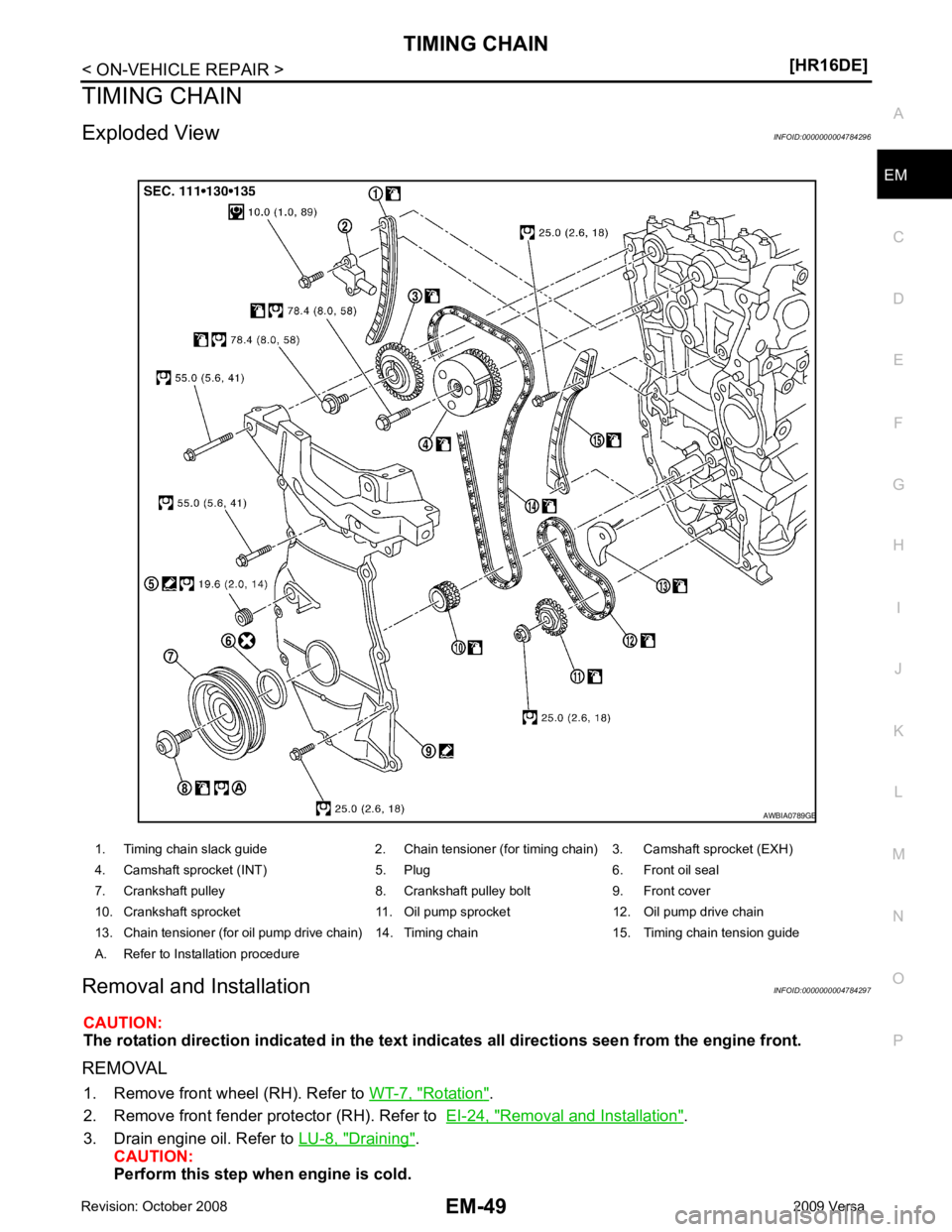
TIMING CHAIN
Exploded View INFOID:0000000004784296
Removal and Installation INFOID:0000000004784297
CAUTION:
The rotation direction indicated in the text indicates all directions seen from the engine front.
REMOVAL 1. Remove front wheel (RH). Refer to WT-7, " Rotation " .
2. Remove front fender protector (RH). Refer to EI-24, " Removal and Installation " .
3. Drain engine oil. Refer to LU-8, " Draining " .
CAUTION:
Perform this step when engine is cold.
1. Timing chain slack guide 2. Chain tensioner (for timing chain) 3. Camshaft sprocket (EXH)
4. Camshaft sprocket (INT) 5. Plug 6. Front oil seal
7. Crankshaft pulley 8. Crankshaft pulley bolt 9. Front cover
10. Crankshaft sprocket 11. Oil pump sprocket 12. Oil pump drive chain
13. Chain tensioner (for oil pump drive chain) 14. Timing chain 15. Timing chain tension guide
A. Refer to Installation procedure
Page 2997 of 4331
![NISSAN LATIO 2009 Service Repair Manual EM-50< ON-VEHICLE REPAIR >
[HR16DE]
TIMING CHAIN
4. Remove the following parts. • Intake manifold: Refer to EM-28, " Exploded View " .
• Drive belt: Refer to EM-15, " Removal and Installation " NISSAN LATIO 2009 Service Repair Manual EM-50< ON-VEHICLE REPAIR >
[HR16DE]
TIMING CHAIN
4. Remove the following parts. • Intake manifold: Refer to EM-28, " Exploded View " .
• Drive belt: Refer to EM-15, " Removal and Installation "](/img/5/57359/w960_57359-2996.png)
EM-50< ON-VEHICLE REPAIR >
[HR16DE]
TIMING CHAIN
4. Remove the following parts. • Intake manifold: Refer to EM-28, " Exploded View " .
• Drive belt: Refer to EM-15, " Removal and Installation " .
• Water pump pulley: Refer to CO-20, " Exploded View " .
• Ground cable (RH)
5. Support the bottom surface of engine using a tr ansmission jack, and then remove the engine mounting
bracket and insulator (RH). Refer to EM-88, " Exploded View " .
6. Remove rocker cover. Refer to EM-46, " Exploded View " .
7. Set No. 1 cylinder at TDC of its compression stroke with the following procedure:
a. Rotate crankshaft pulley (2) clockwise and align TDC mark (without paint mark) (A) to timing indicator (1) on front cover.
b. Make sure the matching marks on each camshaft sprocket are positioned as shown.
• If not, rotate crankshaft pulley one more turn to align matching marks to the positions.
8. Remove crankshaft pulley with the following procedure:
a. Secure crankshaft pulley (1) using a suitable tool (A).
b. Loosen and pull out crankshaft pulley bolts. CAUTION:
Never remove the bolts as they are used as a supporting
point for the pulley puller.
c. Attach Tool (A) in the M 6 thread hole on crankshaft pulley, and remove crankshaft pulley. B : White paint mark (Not use for service) PBIC3673E
1 : Camshaft sprocket (EXH)
2 : Camshaft sprocket (INT)
A : Matching mark (stamp)
B : Matching mark (peripheral stamp line) PBIC3872E
PBIC3710E
B : M6 bolt
Tool number : KV11103000 ( — ) PBIC3711E
Page 2998 of 4331
EM
NP
O
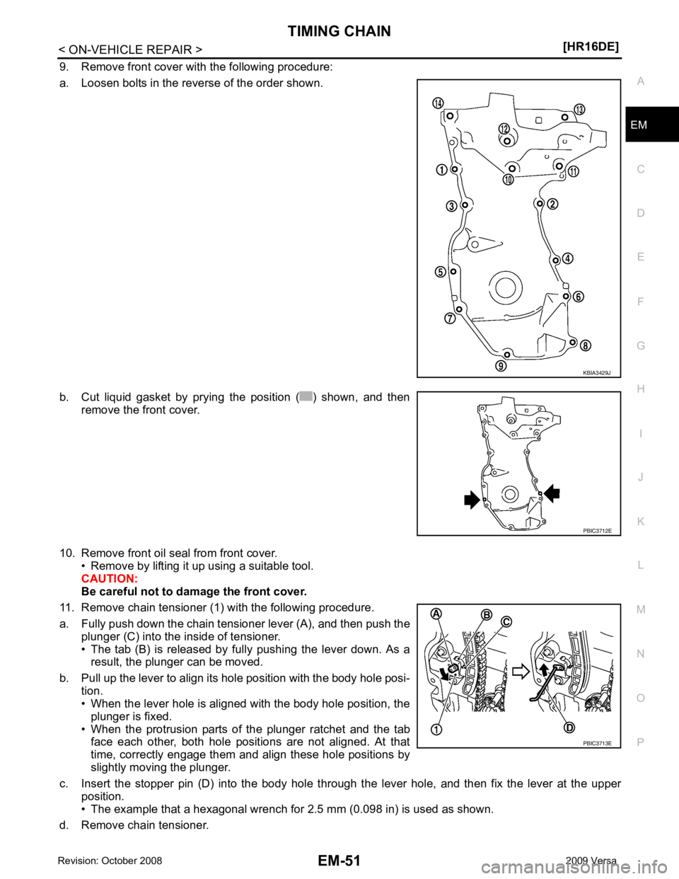
9. Remove front cover with the following procedure:
a. Loosen bolts in the reverse of the order shown.
b. Cut liquid gasket by prying the position ( ) shown, and then remove the front cover.
10. Remove front oil seal from front cover. • Remove by lifting it up using a suitable tool.
CAUTION:
Be careful not to damage the front cover.
11. Remove chain tensioner (1) with the following procedure.
a. Fully push down the chain tensioner lever (A), and then push the plunger (C) into the inside of tensioner.
• The tab (B) is released by fully pushing the lever down. As a result, the plunger can be moved.
b. Pull up the lever to align its hole position with the body hole posi- tion.
• When the lever hole is aligned with the body hole position, the
plunger is fixed.
• When the protrusion parts of the plunger ratchet and the tab face each other, both hole positions are not aligned. At that
time, correctly engage them and align these hole positions by
slightly moving the plunger.
c. Insert the stopper pin (D) into the body hole thr ough the lever hole, and then fix the lever at the upper
position.
• The example that a hexagonal wrench for 2.5 mm (0.098 in) is used as shown.
d. Remove chain tensioner. PBIC3712E
PBIC3713E
Page 2999 of 4331
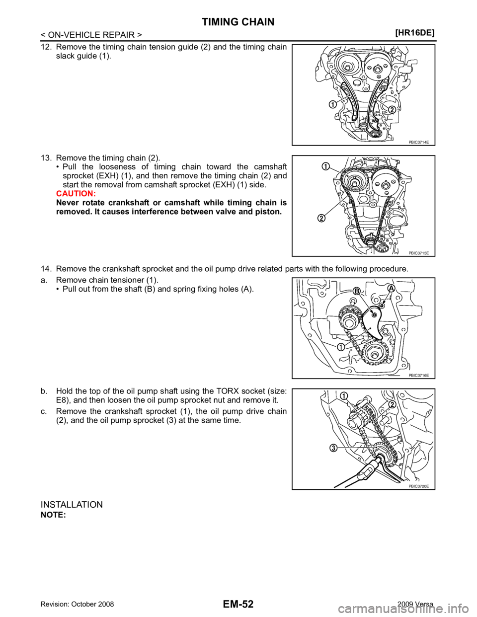
PBIC3715E
PBIC3716E
PBIC3720E
Page 3000 of 4331
EM
NP
O
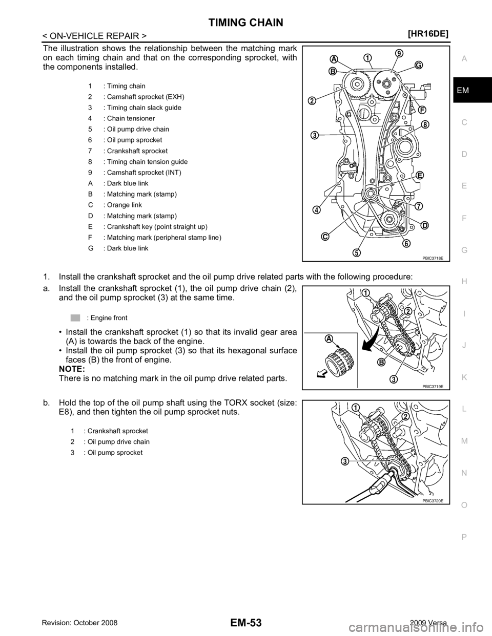
The illustration shows the relationship between the matching mark
on each timing chain and that on the corresponding sprocket, with
the components installed.
1. Install the crankshaft sprocket and the oil pump drive related parts with the following procedure:
a. Install the crankshaft sprocket (1), the oil pump drive chain (2), and the oil pump sprocket (3) at the same time.
• Install the crankshaft sprocket (1) so that its invalid gear area (A) is towards the back of the engine.
• Install the oil pump sprocket (3) so that its hexagonal surface
faces (B) the front of engine.
NOTE:
There is no matching mark in the oil pump drive related parts.
b. Hold the top of the oil pump shaft using the TORX socket (size: E8), and then tighten the oil pump sprocket nuts. 1 : Timing chain
2 : Camshaft sprocket (EXH)
3 : Timing chain slack guide
4 : Chain tensioner
5 : Oil pump drive chain
6 : Oil pump sprocket
7 : Crankshaft sprocket
8 : Timing chain tension guide
9 : Camshaft sprocket (INT)
A : Dark blue link
B : Matching mark (stamp)
C : Orange link
D : Matching mark (stamp)
E : Crankshaft key (point straight up)
F : Matching mark (peripheral stamp line)
G : Dark blue link