NISSAN LATIO 2009 Service Repair Manual
LATIO 2009
NISSAN
NISSAN
https://www.carmanualsonline.info/img/5/57359/w960_57359-0.png
NISSAN LATIO 2009 Service Repair Manual
Trending: height, fuel filter location, navigation, tire pressure, drain bolt, fold seats, check engine light
Page 2971 of 4331
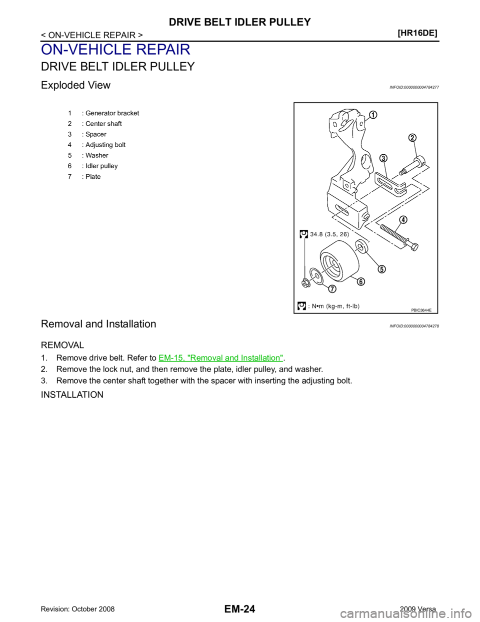
Removal and Installation " .
2. Remove the lock nut, and then remove the plate, idler pulley, and washer.
3. Remove the center shaft together with t he spacer with inserting the adjusting bolt.
INSTALLATION 1 : Generator bracket
2 : Center shaft
3 : Spacer
4 : Adjusting bolt
5 : Washer
6 : Idler pulley
7 : Plate
Page 2972 of 4331
EM
NP
O
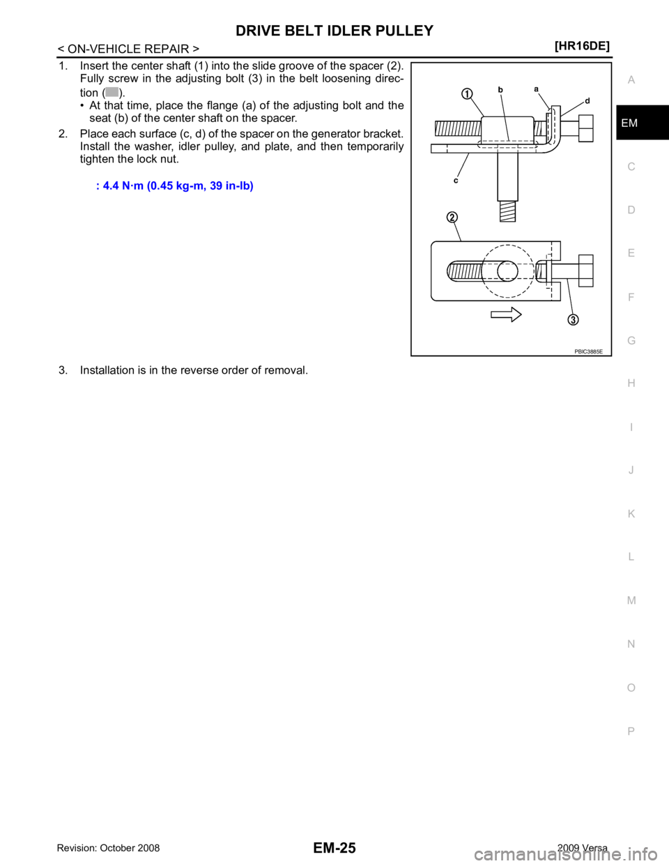
1. Insert the center shaft (1) into the slide groove of the spacer (2).
Fully screw in the adjusting bolt (3) in the belt loosening direc-
tion ( ).
• At that time, place the flange (a) of the adjusting bolt and the seat (b) of the center shaft on the spacer.
2. Place each surface (c, d) of the spacer on the generator bracket. Install the washer, idler pulley, and plate, and then temporarily
tighten the lock nut.
3. Installation is in the reverse order of removal. : 4.4 N·m (0.45 kg-m, 39 in-lb)
Page 2973 of 4331
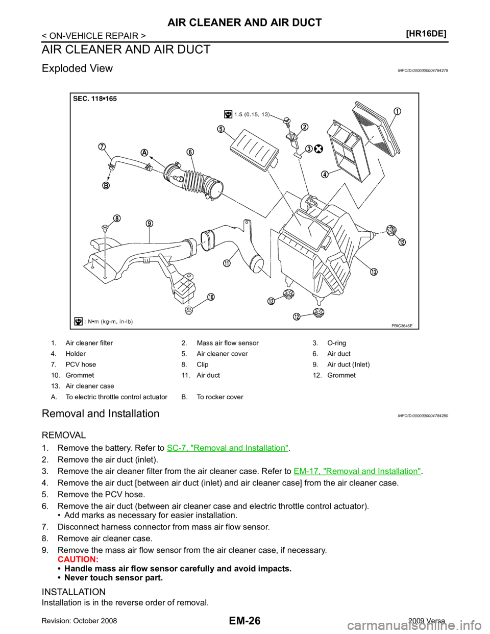
Removal and Installation " .
2. Remove the air duct (inlet).
3. Remove the air cleaner filter from the air cleaner case. Refer to EM-17, " Removal and Installation " .
4. Remove the air duct [between air duct (inlet) and air cleaner case] from the air cleaner case.
5. Remove the PCV hose.
6. Remove the air duct (between air cleaner case and electric throttle control actuator). • Add marks as necessary for easier installation.
7. Disconnect harness connector from mass air flow sensor.
8. Remove air cleaner case.
9. Remove the mass air flow sensor from the air cleaner case, if necessary. CAUTION:
• Handle mass air flow sensor carefully and avoid impacts.
• Never touch sensor part.
INSTALLATION
Installation is in the reverse order of removal. 1. Air cleaner filter 2. Mass air flow sensor 3. O-ring
4. Holder 5. Air cleaner cover 6. Air duct
7. PCV hose 8. Clip 9. Air duct (Inlet)
10. Grommet 11. Air duct 12. Grommet
13. Air cleaner case
A. To electric throttle control actuator B. To rocker cover
Page 2974 of 4331
EM
NP
O
• Align marks. Attach each joint. Screw clamps firmly.
Inspection INFOID:0000000004784281
INSPECTION AFTER REMOVAL Inspect air ducts and air cleaner assembly for crack or tear.
• If anything found, replace air ducts and air cleaner assembly as necessary.
Page 2975 of 4331
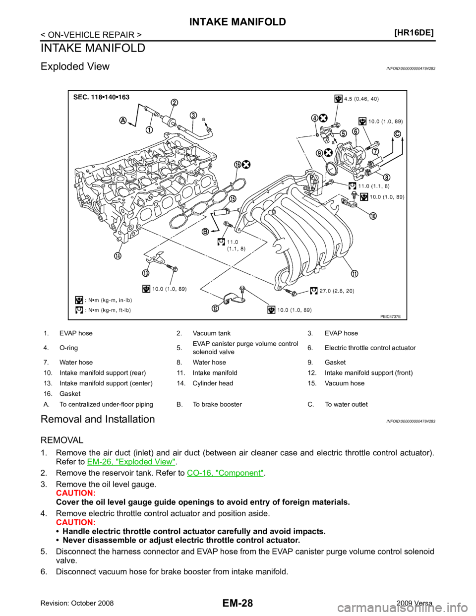
Exploded View " .
2. Remove the reservoir tank. Refer to CO-16, " Component " .
3. Remove the oil level gauge. CAUTION:
Cover the oil level gauge gu ide openings to avoid entry of foreign materials.
4. Remove electric throttle control actuator and position aside. CAUTION:
• Handle electric throttle control act uator carefully and avoid impacts.
• Never disassemble or adjust elect ric throttle control actuator.
5. Disconnect the harness connector and EVAP hose from the EVAP canister purge volume control solenoid
valve.
6. Disconnect vacuum hose for brake booster from intake manifold.
Page 2976 of 4331
EM
NP
O
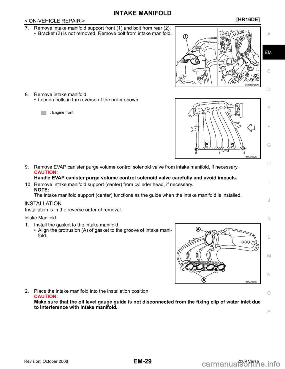
7. Remove intake manifold support front (1) and bolt from rear (2).
• Bracket (2) is not removed. Remove bolt from intake manifold.
8. Remove intake manifold. • Loosen bolts in the reverse of the order shown.
9. Remove EVAP canister purge volume control solenoid valve from intake manifold, if necessary. CAUTION:
Handle EVAP canister purge volume control solenoid valve carefully and avoid impacts.
10. Remove intake manifold support (center) from cylinder head, if necessary. NOTE:
The intake manifold support (center) functions as the guide when the intake manifold is installed.
INSTALLATION Installation is in the reverse order of removal.
Intake Manifold 1. Install the gasket to the intake manifold. • Align the protrusion (A) of gasket to the groove of intake mani-fold.
2. Place the intake manifold into the installation position. CAUTION:
Make sure that the oil level gauge guide is not disconnected from the fixing clip of water inlet due
to interference with intake manifold.
Page 2977 of 4331
THROTTLE VALVE CLOSED POSITION LEARNING : Special
Repair Requirement " .
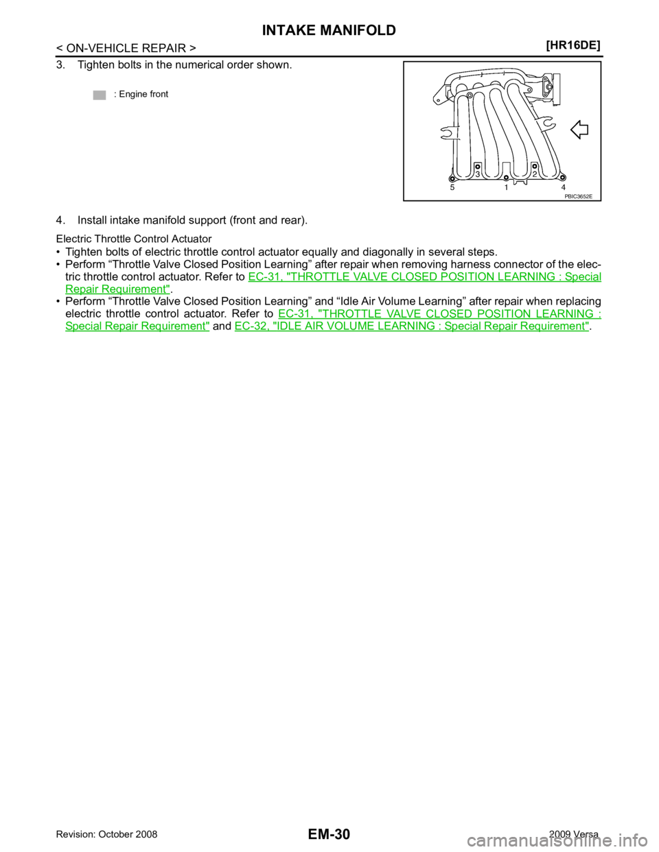
• Perform “Throttle Valve Closed Position Learning” and “Idle Air Volume Learning” after repair when replacing electric throttle control actuator. Refer to EC-31, " THROTTLE VALVE CLOSED
POSITION LEARNING :Special Repair Requirement " and
EC-32, " IDLE AIR VOLUME LEARNING : Special Repair Requirement " .
: Engine front
Page 2978 of 4331
EM
NP
O
EXHAUST MANIFOLD
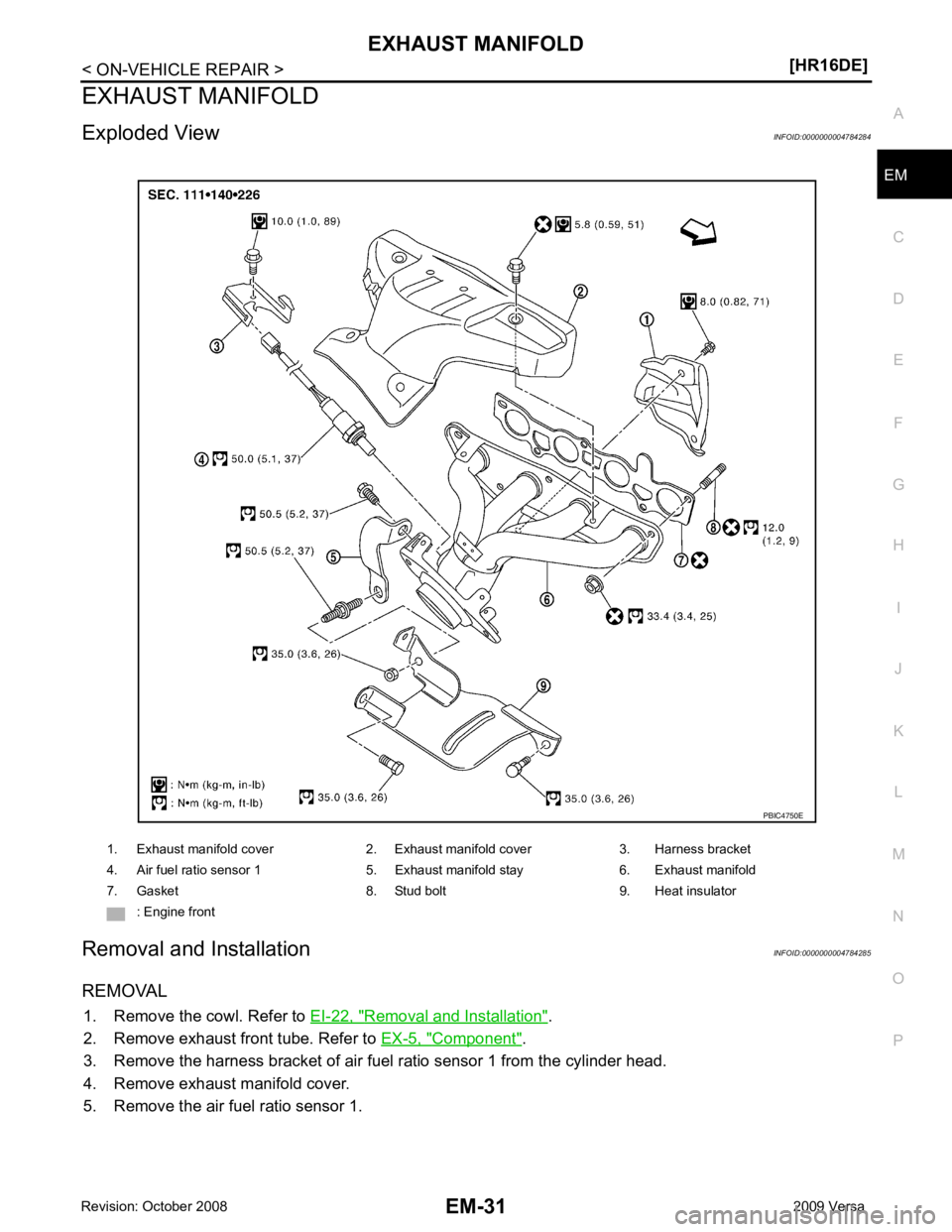
Exploded View INFOID:0000000004784284
Removal and Installation INFOID:0000000004784285
REMOVAL 1. Remove the cowl. Refer to EI-22, " Removal and Installation " .
2. Remove exhaust front tube. Refer to EX-5, " Component " .
3. Remove the harness bracket of air fuel ratio sensor 1 from the cylinder head.
4. Remove exhaust manifold cover.
5. Remove the air fuel ratio sensor 1. 1. Exhaust manifold cover 2. Exhaust manifold cover 3. Harness bracket
4. Air fuel ratio sensor 1 5. Exhaust manifold stay 6. Exhaust manifold
7. Gasket 8. Stud bolt 9. Heat insulator : Engine front
Page 2979 of 4331
Page 2980 of 4331
EXHAUST MANIFOLD
EM-33
< ON-VEHICLE REPAIR >
[HR16DE] C
D E
F
G H
I
J
K L
M A EM
NP
O
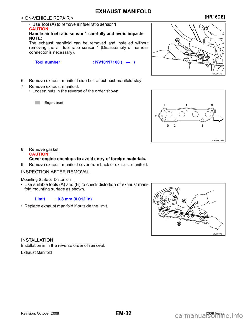
1. Tighten exhaust manifold nuts to specification in two stages in
the numerical order shown.
2. Use Tool (A) to install the air fuel ratio sensor 1. CAUTION:
• Handle it carefully and avoid impacts.
• Before installing a new air fu el ratio sensor 1, clean the
exhaust tube threads using suitable tool and approved
anti-seize lubricant.
• Do not over-tighten the air fu el ratio sensor 1. Doing so
may damage the air fuel rati o sensor 1, resulting in the
MIL coming on. : Engine front ALBIA0625ZZ
Tool number : KV10117100 ( — )
Tool number : — (J-43897-12)
Tool number : — (J-43897-18) PBIC3654E
Trending: brakes, compression ratio, bulb, roof rack, ABS, headlamp, sport mode



![NISSAN LATIO 2009 Service Repair Manual EXHAUST MANIFOLD
EM-33
< ON-VEHICLE REPAIR >
[HR16DE] C
D E
F
G H
I
J
K L
M A EM
NP
O
1. Tighten exhaust manifold nuts to specification in two stages in
the numerical order shown.
2. Use Tool NISSAN LATIO 2009 Service Repair Manual EXHAUST MANIFOLD
EM-33
< ON-VEHICLE REPAIR >
[HR16DE] C
D E
F
G H
I
J
K L
M A EM
NP
O
1. Tighten exhaust manifold nuts to specification in two stages in
the numerical order shown.
2. Use Tool](/img/5/57359/w960_57359-2979.png)