NISSAN LATIO 2009 Service Repair Manual
LATIO 2009
NISSAN
NISSAN
https://www.carmanualsonline.info/img/5/57359/w960_57359-0.png
NISSAN LATIO 2009 Service Repair Manual
Trending: fuse diagram, lock, wheel bolt torque, pairing phone, wiring, rear view mirror, spare tire
Page 3351 of 4331
Removal and Installation " .
2. Disconnect the harness connector of rear door speaker.
3. Position the sealing screen aside. NOTE:
If the sealing screen is reused, cut the butyl-tape so that a part of the butyl-tape remains on the sealing
screen.
4. Remove partition sash bolt and screw, pull the partition sash downward and tilt the upper end of the sash forward to pull out
the sash upward.
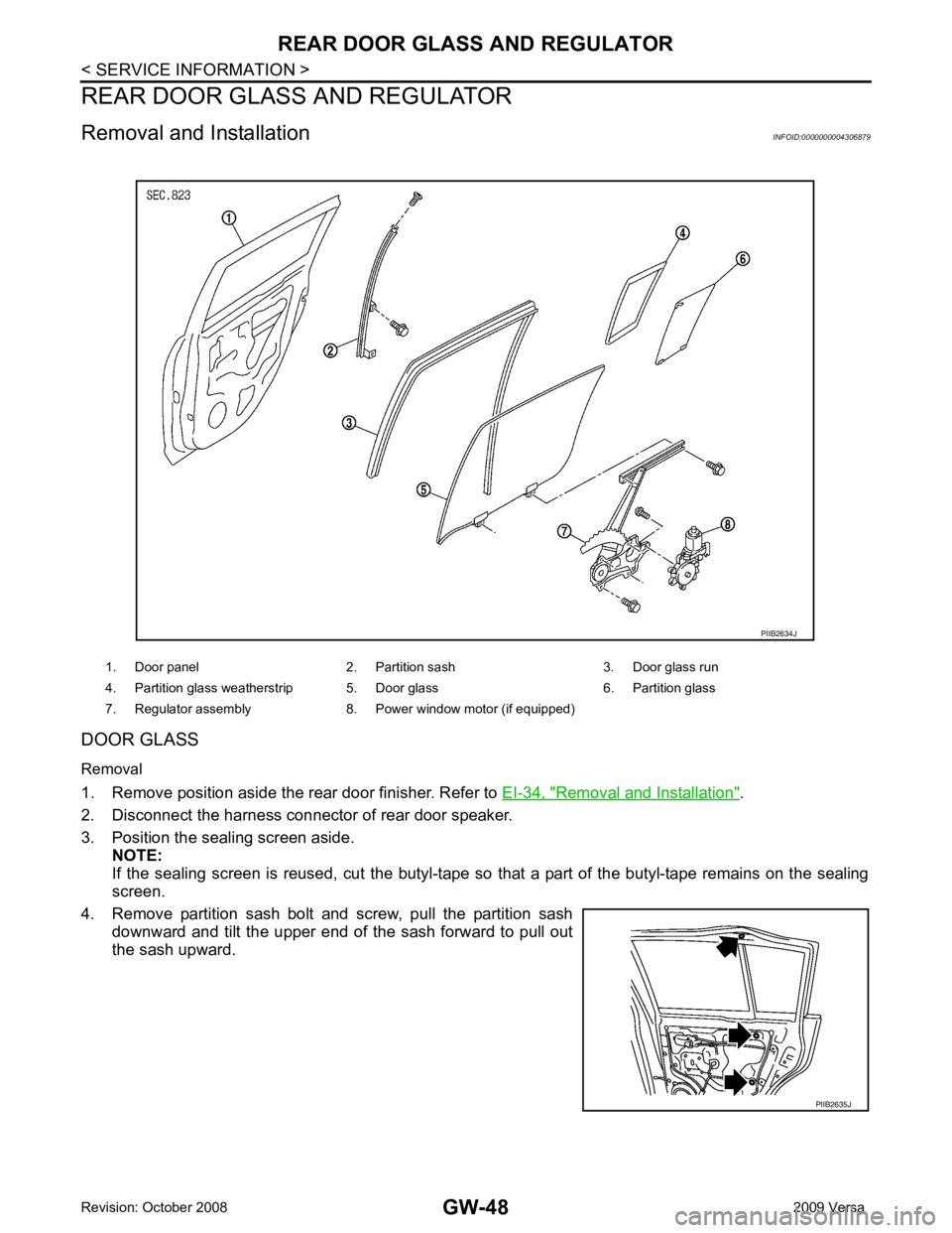
1. Door panel 2. Partition sash 3. Door glass run
4. Partition glass weatherstrip 5. Door glass 6. Partition glass
7. Regulator assembly 8. Power window motor (if equipped) PIIB2635J
Page 3352 of 4331
GW
N
O P
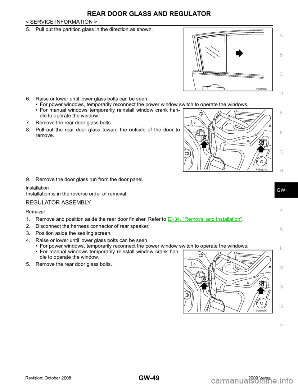
5. Pull out the partition glass in the direction as shown.
6. Raise or lower until lower glass bolts can be seen. • For power windows, temporarily reconnect the power window switch to operate the windows.
• For manual windows temporarily reinstall window crank han-
dle to operate the window.
7. Remove the rear door glass bolts.
8. Pull out the rear door glass toward the outside of the door to remove.
9. Remove the door glass run from the door panel.
Installation Installation is in the reverse order of removal.
REGULATOR ASSEMBLY
Removal 1. Remove and position aside the rear door finisher. Refer to EI-34, " Removal and Installation " .
2. Disconnect the harness connector of rear speaker.
3. Position aside the sealing screen.
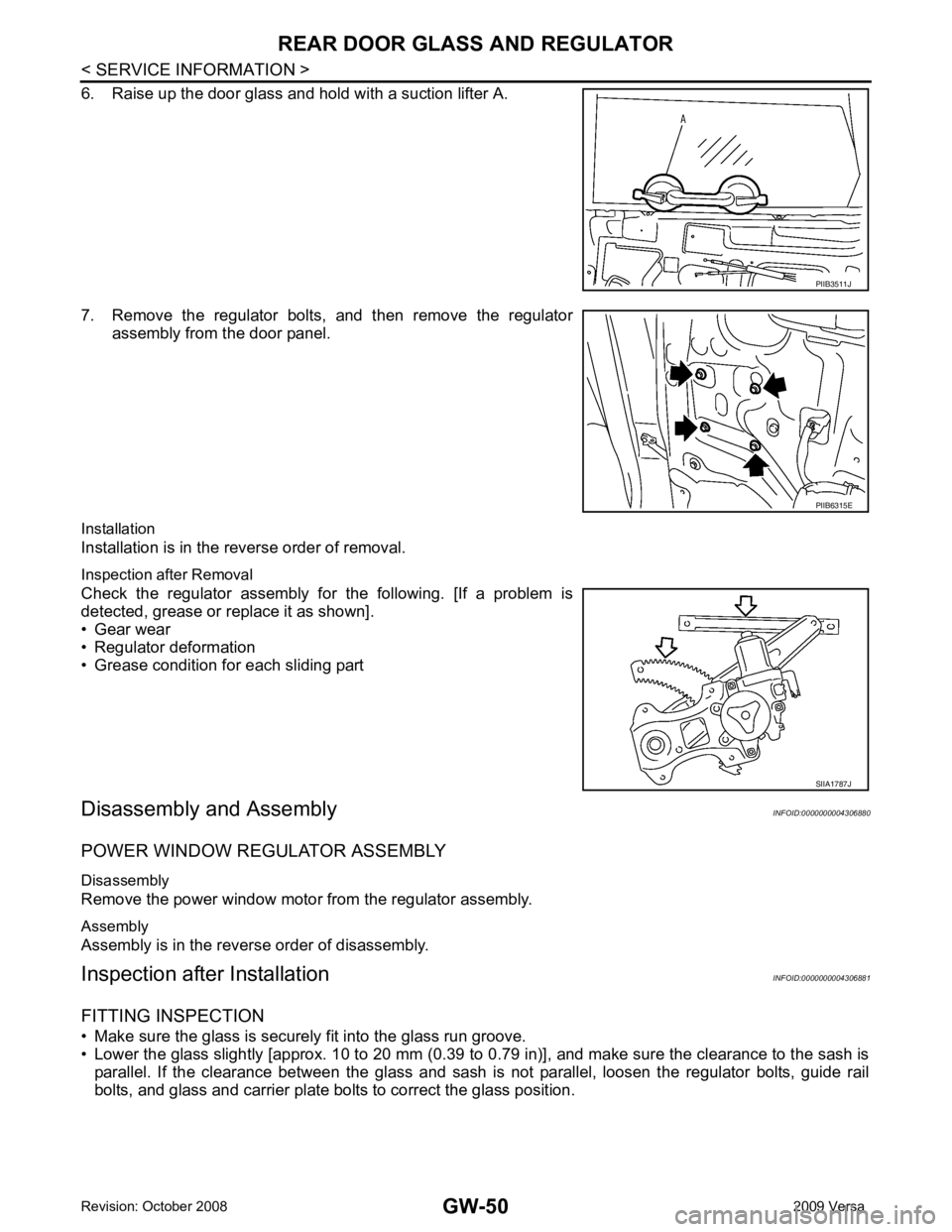
4. Raise or lower until lower glass bolts can be seen. • For power windows, temporarily reconnect the power window switch to operate the windows.
• For manual windows temporarily reinstall window crank han- dle to operate the window.
5. Remove the rear door glass bolts. PIIB2637J
PIIB2637J
Page 3353 of 4331
Page 3354 of 4331
GW
N
O P
REAR WINDOW DEFOGGER
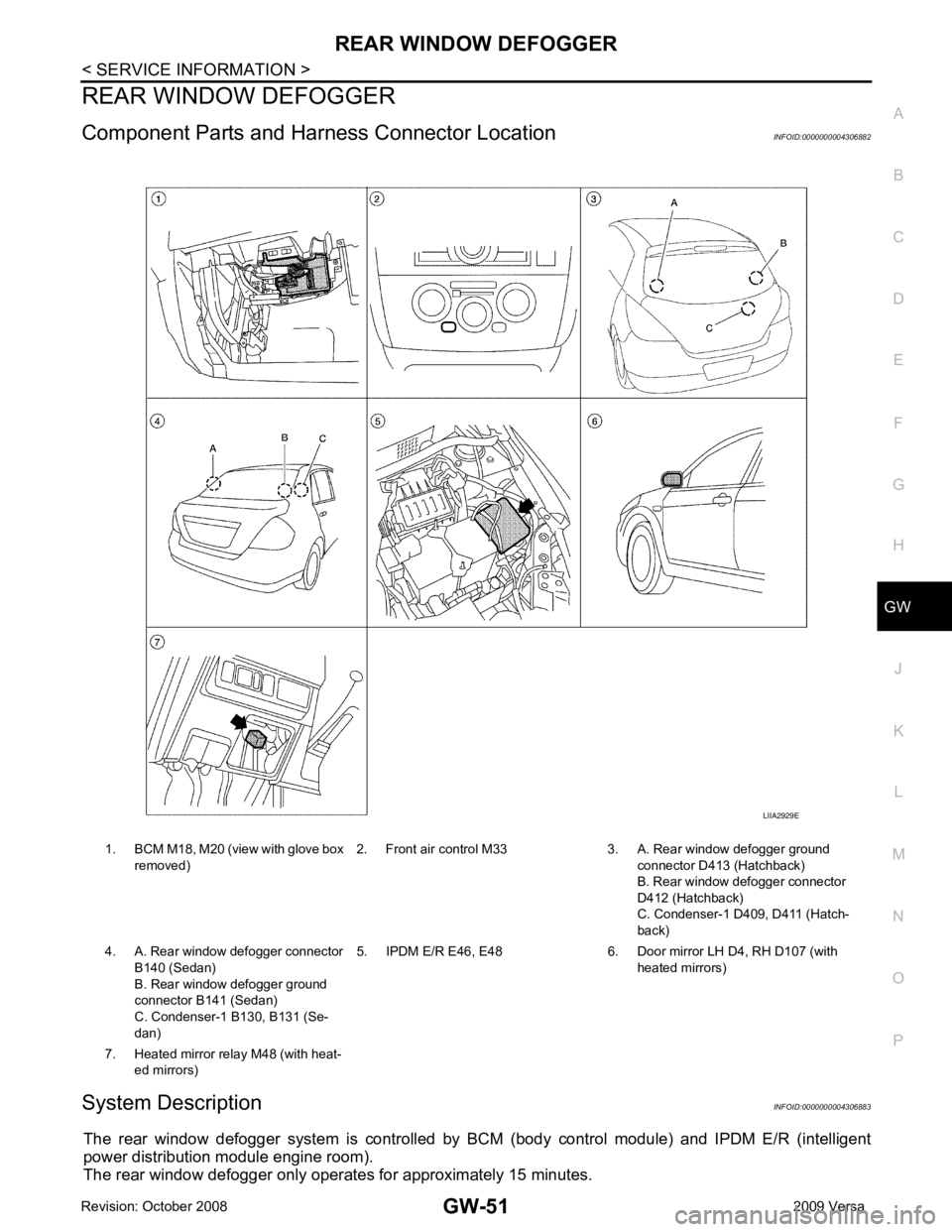
Component Parts and Har ness Connector Location INFOID:0000000004306882
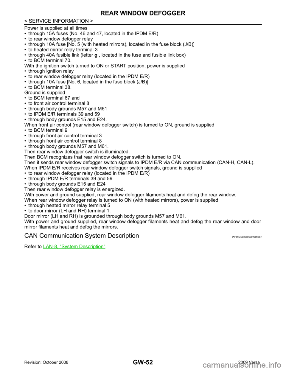
System Description INFOID:0000000004306883
The rear window defogger system is controlled by BCM (body control module) and IPDM E/R (intelligent
power distribution module engine room).
The rear window defogger only operates for approximately 15 minutes. 1. BCM M18, M20 (view with glove box
removed) 2. Front air control M33 3. A. Rear window defogger ground
connector D413 (Hatchback)
B. Rear window defogger connector
D412 (Hatchback)
C. Condenser-1 D4 09, D411 (Hatch-
back)
4. A. Rear window defogger connector B140 (Sedan)
B. Rear window defogger ground
connector B141 (Sedan)
C. Condenser-1 B130, B131 (Se-
dan) 5. IPDM E/R E46, E48 6. Door mirror LH D4, RH D107 (with
heated mirrors)
7. Heated mirror relay M48 (with heat- ed mirrors)
Page 3355 of 4331
Page 3356 of 4331
GW
N
O P
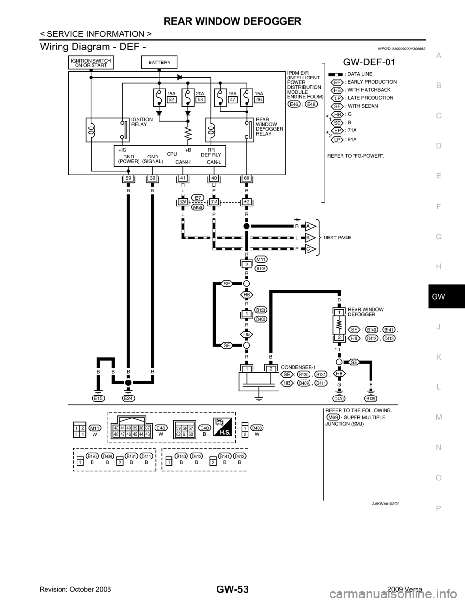
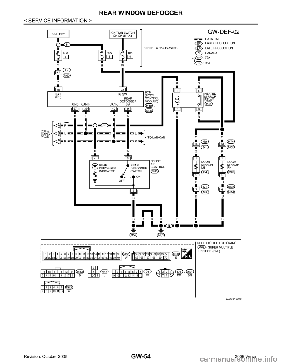
Wiring Diagram - DEF -
INFOID:0000000004306885 B
Page 3357 of 4331
Page 3358 of 4331
GW
N
O P
Terminal and Reference Value for BCM
INFOID:0000000004306886
Refer to BCS-11, " Terminal and Reference Value for BCM " .
Terminal and Reference Value for IPDM E/R INFOID:0000000004306887
Refer to PG-24, " Terminal and Reference Value for IPDM E/R " .
Work Flow INFOID:0000000004306888
1. Check the symptom and customer's requests.
2. Understand the outline of system. Refer to GW-51, " System Description " .
3. According to the trouble diagnosis chart, repair or replace the cause of the malfunction. Refer to GW-55," Trouble Diagnosis Symptom Chart " .
4. Does rear window defogger operate normally? YES: GO TO 5, NO: GO TO 3.
5. Inspection End.
CONSULT-III Function (BCM) INFOID:0000000004306889
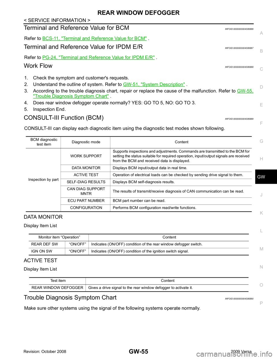
CONSULT-III can display each diagnostic item using the diagnostic test modes shown following.
DATA MONITOR
Display Item List
ACTIVE TEST
Display Item List
Trouble Diagnosis Symptom Chart INFOID:0000000004306890
Make sure other systems using the signal of the following systems operate normally.
BCM diagnostic
test item Diagnostic mode Content
Inspection by part WORK SUPPORT
Supports inspections and adjustments. Commands are transmitted to the BCM for
setting the status suitable for required operation, input/output signals are received
from the BCM and received data is displayed.
DATA MONITOR Displays BCM input/output data in real time. ACTIVE TEST Operation of electrical loads can be checked by sending drive signal to them.
SELF-DIAG RESULTS Displays BCM self-diagnosis results. CAN DIAG SUPPORT MNTR The results of transmit/receive diagnosis of CAN communication can be read.
ECU PART NUMBER BCM part number can be read. CONFIGURATION Performs BCM configuration read/write functions. Monitor item “Operation” Content
REAR DEF SW “ON/OFF” Indicates (ON/OFF) condition of the rear window defogger switch.
IGN ON SW “ON/OFF” Indicates (ON/OFF) condition of the ignition switch signal. Test item Content
REAR WINDOW DEFOGGER Gives a drive signal to the rear window defogger to activate it.
Page 3359 of 4331
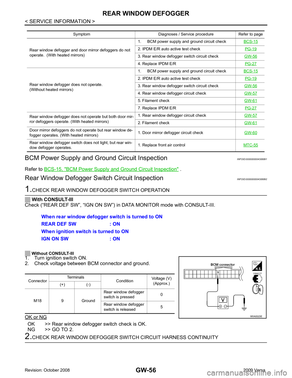
BCM Power Supply and Ground Circuit Inspection " .
Rear Window Defogger Swit ch Circuit Inspection INFOID:0000000004306892OK >> Rear window defogger switch check is OK.
NG >> GO TO 2. 2. IPDM E/R auto active test check
PG-19 3. Rear window defogger switch circuit check
GW-56 4. Replace IPDM E/R
PG-27Rear window defogger does not operate.
(Without heated mirrors) 1. BCM power supply and ground circuit check
BCS-15 2. IPDM E/R auto active test check
PG-19 3. Rear window defogger switch circuit check
GW-56 4. Rear window defogger circuit check
GW-57 5. Filament check
GW-61 7. Replace IPDM E/R
PG-27Rear window defogger does not operate but both door mir-
ror defoggers operate. (With heated mirrors) 1. Rear window defogger circuit check
GW-57 2. Filament check
GW-61Door mirror defoggers do not operate but rear window de-
fogger operates. (With heated mirrors) 1. Door mirror defogger circuit check
GW-60Rear window defogger switch does not light, but rear win-
dow defogger operates. 1. Replace front air control
MTC-55
Page 3360 of 4331
GW
N
O P
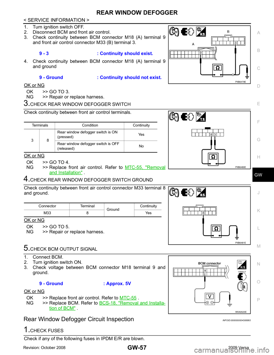
1. Turn ignition switch OFF.
2. Disconnect BCM and front air control.
3. Check continuity between BCM connector M18 (A) terminal 9
and front air control connector M33 (B) terminal 3.
4. Check continuity between BCM connector M18 (A) terminal 9 and ground
OK or NG OK >> GO TO 3.
NG >> Repair or replace harness. OK >> GO TO 4.
NG >> Replace front air control. Refer to MTC-55, " Removal
and Installation " .
OK >> GO TO 5.
NG >> Repair or replace harness. OK >> Replace front air control. Refer to
MTC-55 .
NG >> Replace BCM. Refer to BCS-18, " Removal and Installa-
tion of BCM " .
Rear Window Defogger Circuit Inspection INFOID:0000000004306893
Trending: torque, heating, trailer, radio antenna, charging, engine, brakes
