NISSAN LATIO 2009 Service Repair Manual
LATIO 2009
NISSAN
NISSAN
https://www.carmanualsonline.info/img/5/57359/w960_57359-0.png
NISSAN LATIO 2009 Service Repair Manual
Trending: battery replacement, weight, overheating, timing belt, ground clearance, dead battery, recommended oil
Page 3381 of 4331
IP
N
O P
ON-VEHICLE REPAIR
INSTRUMENT PANEL ASSEMBLY
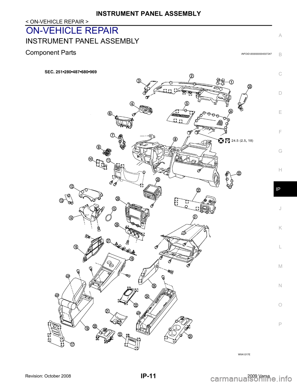
Component Parts INFOID:0000000004307247
Page 3382 of 4331
Removal and Installation " .
4. Remove front pillar garnish. Refer to EI-39 .
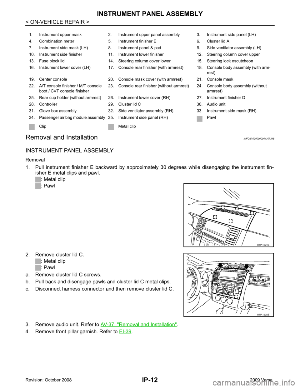
1. Instrument upper mask 2. Instrument upper panel assembly 3. Instrument side panel (LH)
4. Combination meter 5. Instrument finisher E 6. Cluster lid A
7. Instrument side mask (LH) 8. Instrument panel & pad 9. Side ventilator assembly (LH)
10. Instrument side finisher 11. Instrument lower finisher 12. Steering column cover upper
13. Fuse block lid 14. Steering column cover lower 15. Steering lock escutcheon
16. Instrument lower cover (LH) 17. Console rear finisher (with armrest) 18. Console body assembly (with arm- rest)
19. Center console 20. Console mask cover (with armrest) 21. Console mask
22. A/T console finisher / M/T console boot / CVT console finisher 23. Console rear finisher (without armrest) 24. Console body assembly (without
armrest)
25. Rear cup holder (without armrest) 26. Instrument lower cover (RH) 27. Instrument finisher D
28. Controller 29. Cluster lid C 30. Audio unit
31. Glove box assembly 32. Side ventilator assembly (RH) 33. Instrument side mask (RH)
34. Passenger air bag module assembly 35. Instrument side panel (RH) Pawl
Clip Metal clip WIIA1225E
Page 3383 of 4331
IP
N
O P
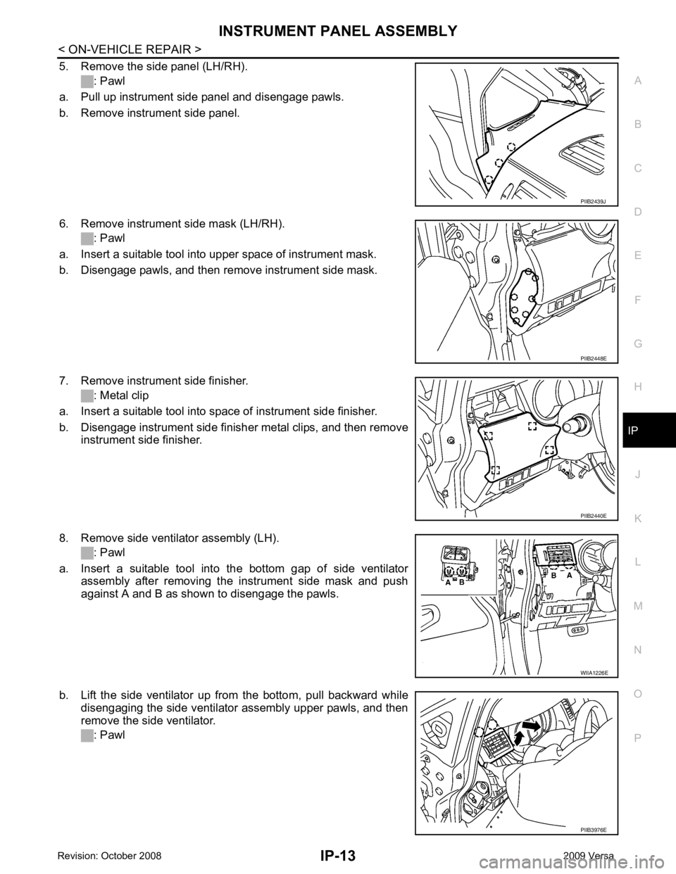
5. Remove the side panel (LH/RH).
: Pawl
a. Pull up instrument side panel and disengage pawls.
b. Remove instrument side panel.
6. Remove instrument side mask (LH/RH). : Pawl
a. Insert a suitable tool into upper space of instrument mask.
b. Disengage pawls, and then remove instrument side mask.
7. Remove instrument side finisher. : Metal clip
a. Insert a suitable tool into space of instrument side finisher.
b. Disengage instrument side finisher metal clips, and then remove instrument side finisher.
8. Remove side ventilator assembly (LH). : Pawl
a. Insert a suitable tool into the bottom gap of side ventilator assembly after removing the instrument side mask and push
against A and B as shown to disengage the pawls.
b. Lift the side ventilator up from the bottom, pull backward while disengaging the side ventilator assembly upper pawls, and then
remove the side ventilator.
: Pawl PIIB2448E
PIIB2440E
PIIB3976E
Page 3384 of 4331
Removal and Installation " .
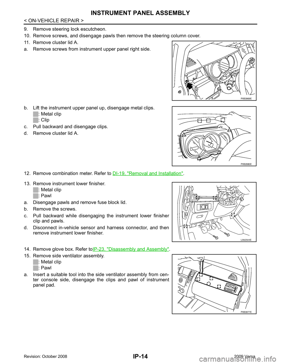
13. Remove instrument lower finisher. : Metal clip
: Pawl
a. Disengage pawls and remove fuse block lid.
b. Remove the screws.
c. Pull backward while disengaging the instrument lower finisher clip and pawls.
d. Disconnect in-vehicle sensor and harness connector, and then remove instrument lower finisher.
14. Remove glove box. Refer to IP-23, " Disassembly and Assembly " .
15. Remove side ventilator assembly. : Metal clip
: Pawl
a. Insert a suitable tool into the side ventilator assembly from cen- ter console side, disengage the clips and pawl of instrument
panel pad. PIIB2880E
PIIB3977E
Page 3385 of 4331
IP
N
O P
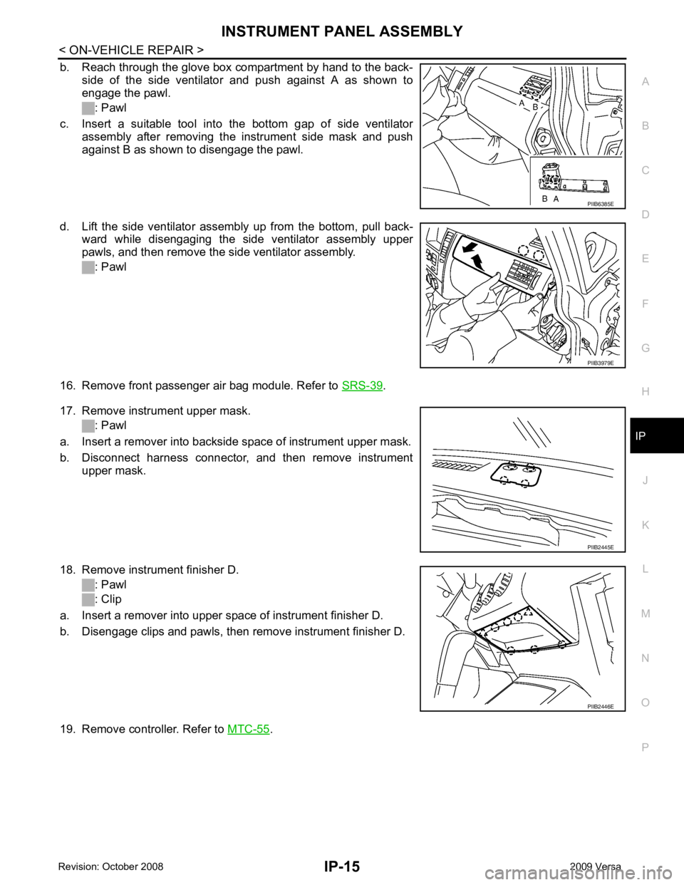
b. Reach through the glove box compartment by hand to the back-
side of the side ventilator and push against A as shown to
engage the pawl.
: Pawl
c. Insert a suitable tool into the bottom gap of side ventilator assembly after removing the instrument side mask and push
against B as shown to disengage the pawl.
d. Lift the side ventilator assembly up from the bottom, pull back- ward while disengaging the side ventilator assembly upper
pawls, and then remove the side ventilator assembly.
: Pawl
16. Remove front passenger air bag module. Refer to SRS-39 .
17. Remove instrument upper mask. : Pawl
a. Insert a remover into backside space of instrument upper mask.
b. Disconnect harness connector, and then remove instrument upper mask.
18. Remove instrument finisher D. : Pawl
: Clip
a. Insert a remover into upper space of instrument finisher D.
b. Disengage clips and pawls, then remove instrument finisher D.
19. Remove controller. Refer to MTC-55 . PIIB3979E
PIIB2446E
Page 3386 of 4331
.
22. Remove wiper & washer switch. Refer to WW-23, " Removal and Installation of Front Wiper and Washer
Switch " .
23. Remove hood opener handle and fuel filler lid opener handle. Refer to BL-15, " Removal and Installation of
Hood Lock Control " .
24. Remove screws, and then remove instrument panel & pad from passenger door opening portion.
Installation
Installation is in the reverse order of removal.
CLUSTER LID A
Removal
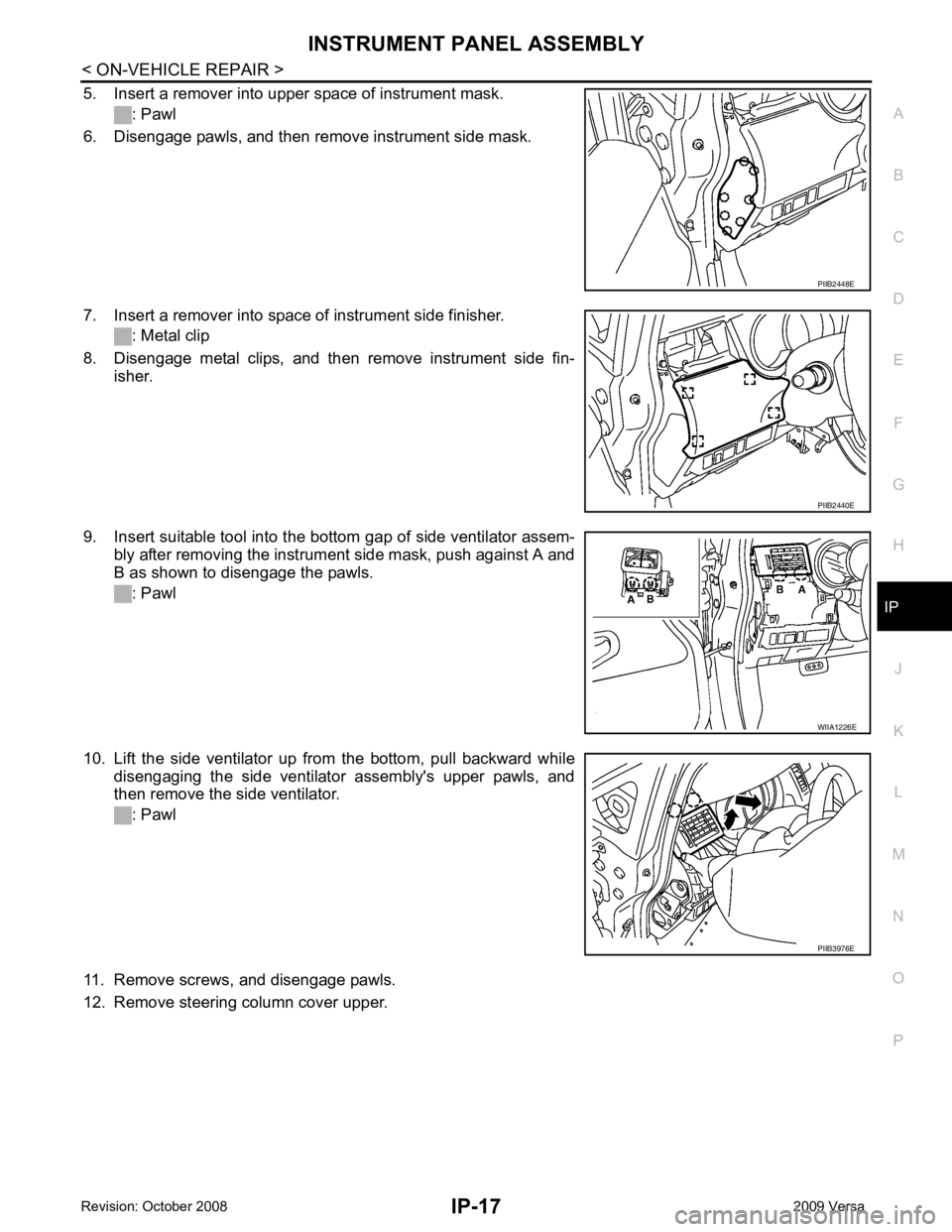
1. Pull instrument finisher E backward by approximately 30 degrees while disengaging the metal clips and pawl.
: Metal clip
: Pawl
2. Remove front pillar garnish. Refer to EI-39 .
3. Pull up instrument side panel and disengage pawls. : Pawl
4. Remove instrument side panel. WIIA1224E
PIIB2439J
Page 3387 of 4331
INSTRUMENT PANEL ASSEMBLY
IP-17
< ON-VEHICLE REPAIR >
C
D E
F
G H
J
K L
M A
B IP
N
O P
5. Insert a remover into upper space of instrument mask.
: Pawl
6. Disengage pawls, and then remove instrument side mask.
7. Insert a remover into space of instrument side finisher. : Metal clip
8. Disengage metal clips, and then remove instrument side fin- isher.
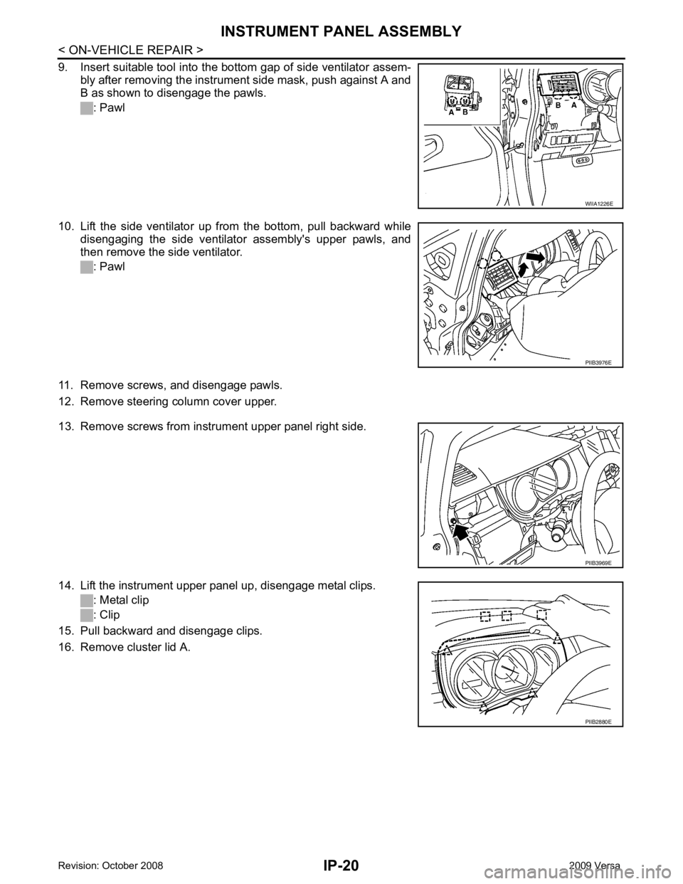
9. Insert suitable tool into the bottom gap of side ventilator assem- bly after removing the instrument side mask, push against A and
B as shown to disengage the pawls.
: Pawl
10. Lift the side ventilator up from the bottom, pull backward while disengaging the side ventilator assembly's upper pawls, and
then remove the side ventilator.
: Pawl
11. Remove screws, and disengage pawls.
12. Remove steering column cover upper. PIIB2448E
PIIB2440E
WIIA1226E
PIIB3976E
Page 3388 of 4331
IP-18< ON-VEHICLE REPAIR >
INSTRUMENT PANEL ASSEMBLY
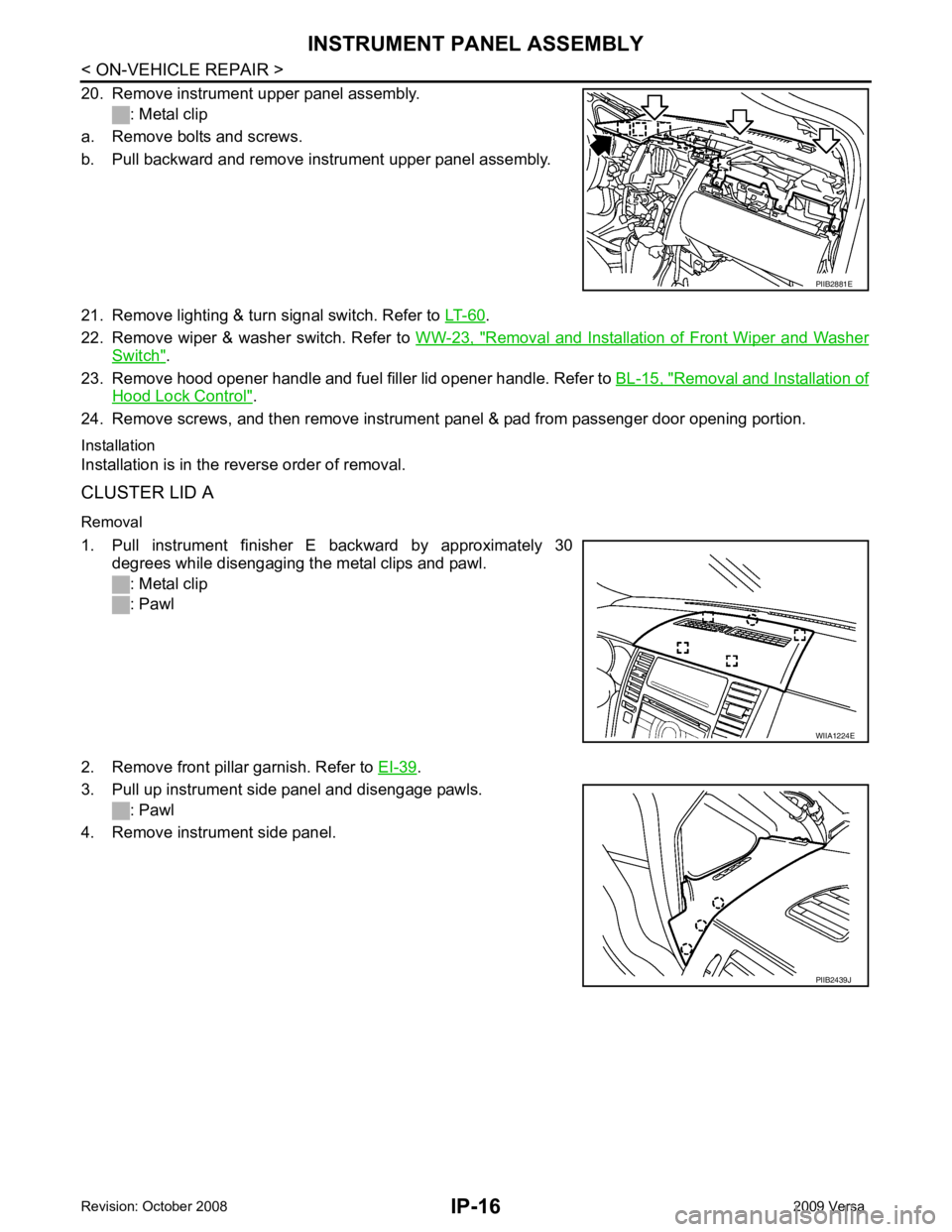
13. Remove screws from instrument upper panel right side.
14. Lift the instrument upper panel up, disengage metal clips. : Metal clip
: Clip
15. Pull backward and disengage clips.
16. Remove cluster lid A.
Installation
Installation is in the reverse order of removal.
CLUSTER LID C
Removal
1. Pull instrument finisher E backward by approximately 30 degrees while disengaging the metal clips and pawl.
: Metal clip
: Pawl
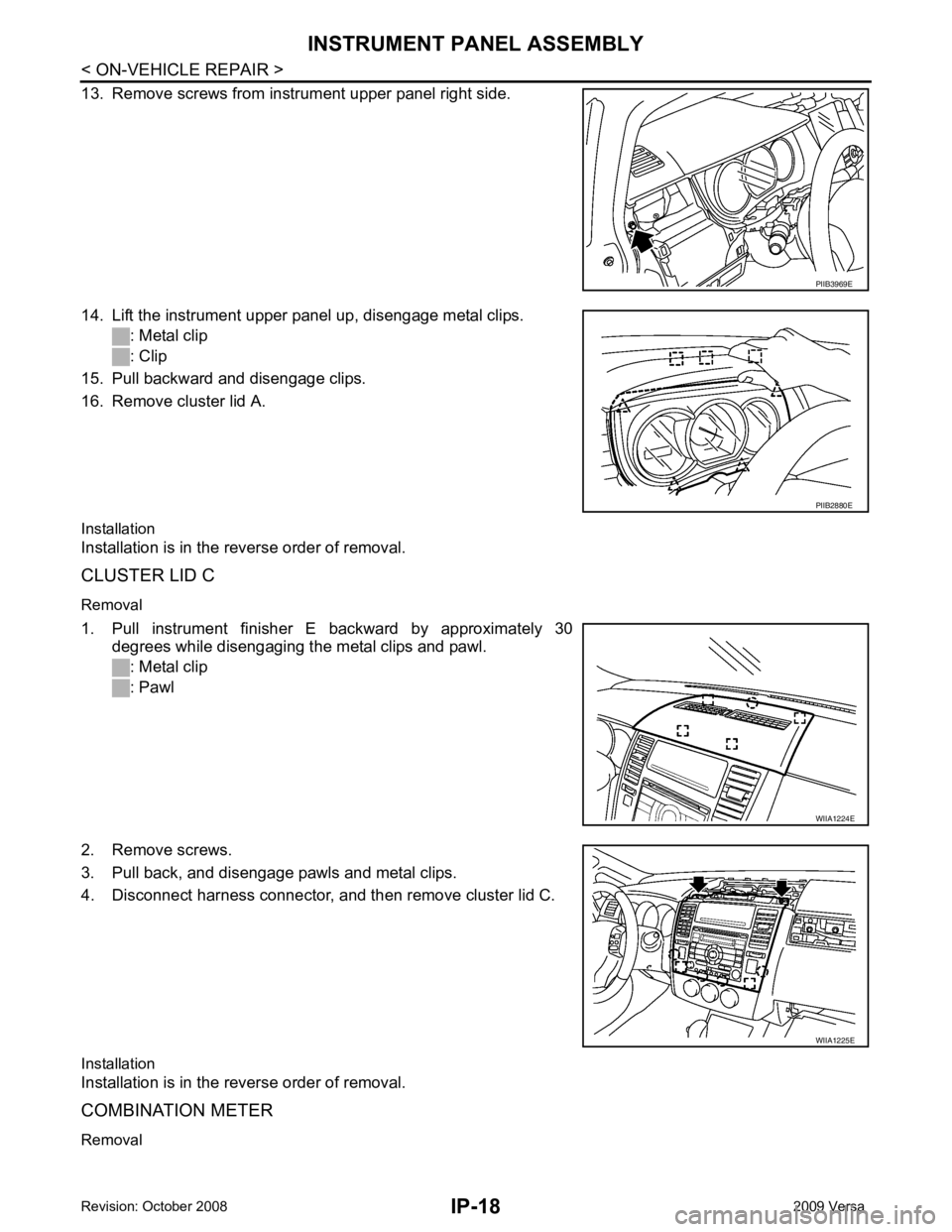
2. Remove screws.
3. Pull back, and disengage pawls and metal clips.
4. Disconnect harness connector, and then remove cluster lid C.
Installation
Installation is in the reverse order of removal.
COMBINATION METER
Removal PIIB3969E
PIIB2880E
WIIA1224E
WIIA1225E
Page 3389 of 4331
INSTRUMENT PANEL ASSEMBLY
IP-19
< ON-VEHICLE REPAIR >
C
D E
F
G H
J
K L
M A
B IP
N
O P
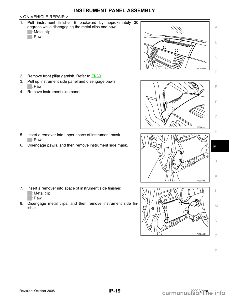
1. Pull instrument finisher E backward by approximately 30
degrees while disengaging the metal clips and pawl.
: Metal clip
: Pawl
2. Remove front pillar garnish. Refer to EI-39 .
3. Pull up instrument side panel and disengage pawls. : Pawl
4. Remove instrument side panel.
5. Insert a remover into upper space of instrument mask. : Pawl
6. Disengage pawls, and then remove instrument side mask.
7. Insert a remover into space of instrument side finisher. : Metal clip
: Pawl
8. Disengage metal clips, and then remove instrument side fin- isher. WIIA1224E
PIIB2439J
PIIB2448E
PIIB2440E
Page 3390 of 4331
IP-20< ON-VEHICLE REPAIR >
INSTRUMENT PANEL ASSEMBLY
9. Insert suitable tool into the bottom gap of side ventilator assem- bly after removing the instrument side mask, push against A and
B as shown to disengage the pawls.
: Pawl
10. Lift the side ventilator up from the bottom, pull backward while disengaging the side ventilator assembly's upper pawls, and
then remove the side ventilator.
: Pawl
11. Remove screws, and disengage pawls.
12. Remove steering column cover upper.
13. Remove screws from instrument upper panel right side.
14. Lift the instrument upper panel up, disengage metal clips. : Metal clip
: Clip
15. Pull backward and disengage clips.
16. Remove cluster lid A. WIIA1226E
PIIB3976E
PIIB3969E
PIIB2880E
Trending: radiator, instrument panel, battery capacity, windshield wipers, steering, trunk, oil change
