NISSAN LATIO 2009 Service Repair Manual
LATIO 2009
NISSAN
NISSAN
https://www.carmanualsonline.info/img/5/57359/w960_57359-0.png
NISSAN LATIO 2009 Service Repair Manual
Trending: air condition, battery, octane, child seat, wheel, suspension, adding oil
Page 3361 of 4331
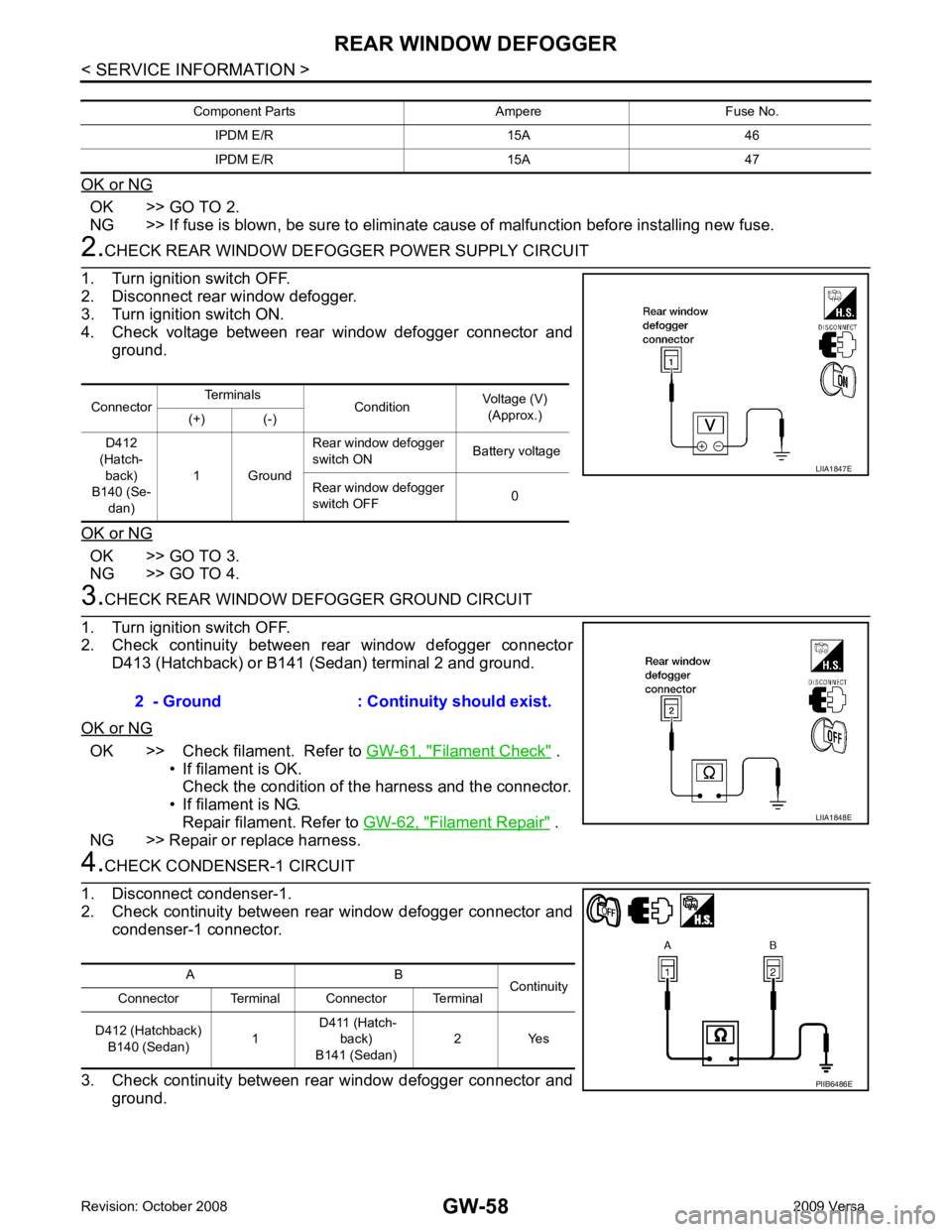
OK >> GO TO 2.
NG >> If fuse is blown, be sure to eliminate cause of malfunction before installing new fuse. OK >> GO TO 3.
NG >> GO TO 4. OK >> Check filament. Refer to
GW-61, " Filament Check " .
• If filament is OK.
Check the condition of the harness and the connector.
• If filament is NG. Repair filament. Refer to GW-62, " Filament Repair " .
NG >> Repair or replace harness. Connector
Terminals
ConditionVoltage (V)
(Approx.)
(+) (-)
D412
(Hatch- back)
B140 (Se-
dan) 1 Ground Rear window defogger
switch ON Battery voltage
Rear window defogger
switch OFF 0
Page 3362 of 4331
GW
N
O P
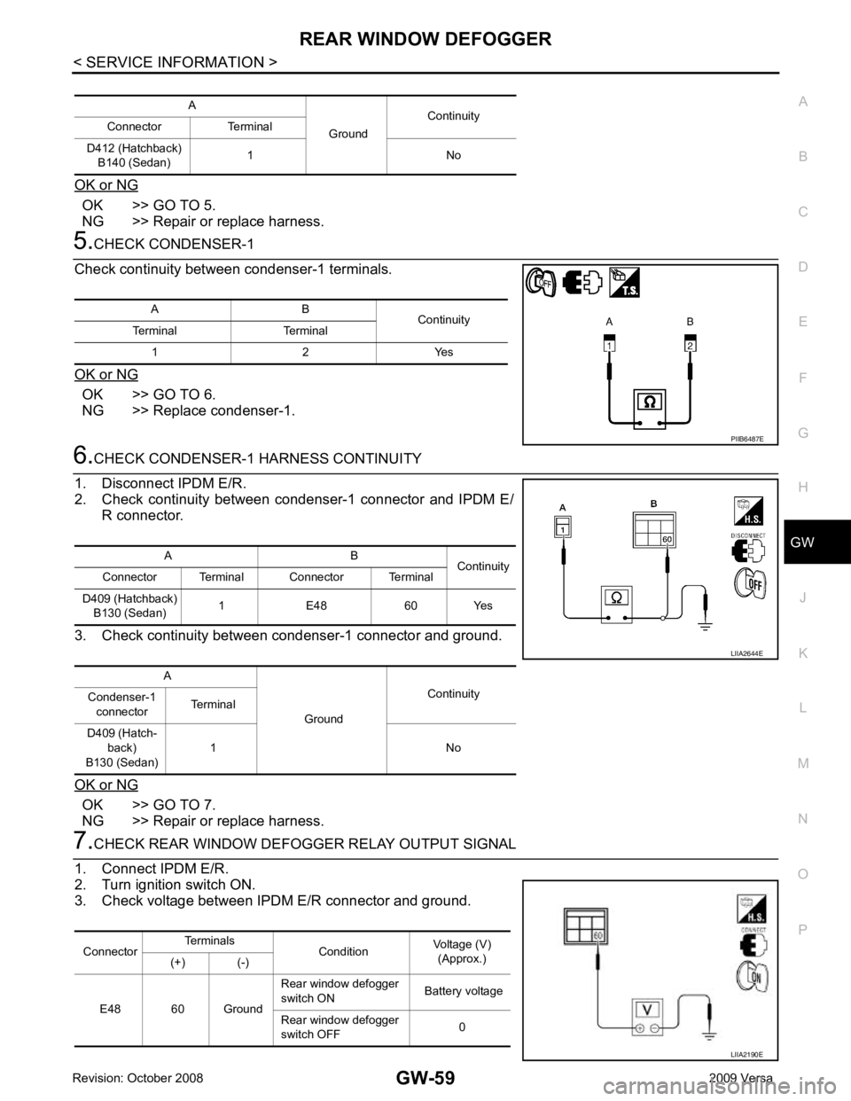
OK or NG OK >> GO TO 5.
NG >> Repair or replace harness. OK >> GO TO 6.
NG >> Replace condenser-1. OK >> GO TO 7.
NG >> Repair or replace harness. A B
Continuity
Terminal Terminal
1 2 Yes
Page 3363 of 4331
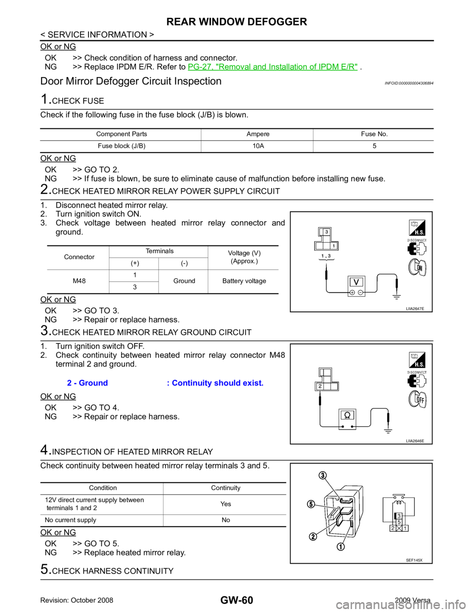
OK >> Check condition of harness and connector.
NG >> Replace IPDM E/R. Refer to PG-27, " Removal and Installation of IPDM E/R " .
Door Mirror Defogger Circuit Inspection INFOID:0000000004306894OK >> GO TO 2.
NG >> If fuse is blown, be sure to eliminate cause of malfunction before installing new fuse. OK >> GO TO 3.
NG >> Repair or replace harness. OK >> GO TO 4.
NG >> Repair or replace harness. OK >> GO TO 5.
NG >> Replace heated mirror relay. Connector
Terminals
Voltage (V)
(Approx.)
(+) (-)
M48 1
Ground Battery voltage
3
Page 3364 of 4331
GW
N
O P
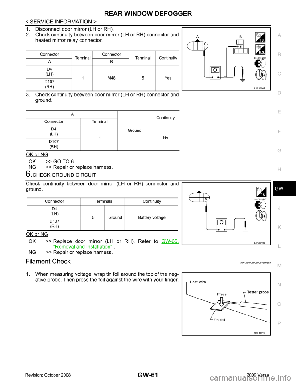
1. Disconnect door mirror (LH or RH).
2. Check continuity between door mirror (LH or RH) connector and heated mirror relay connector.
3. Check continuity between door mirror (LH or RH) connector and ground.
OK or NG OK >> GO TO 6.
NG >> Repair or replace harness. OK >> Replace door mirror (LH or RH). Refer to
GW-65," Removal and Installation " .
NG >> Repair or replace harness.
Filament Check INFOID:0000000004306895
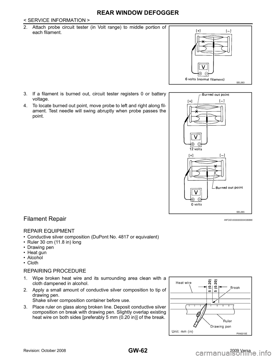
1. When measuring voltage, wrap tin foil around the top of the neg- ative probe. Then press the foil against the wire with your finger.Connector
TerminalConnector
Terminal Continuity
A B
D4
(LH) 1 M48 5 Yes
D107
(RH)
A GroundContinuity
Connector Terminal
D4
(LH) 1 No
D107
(RH) SEL122R
Page 3365 of 4331
Page 3366 of 4331
GW
N
O P
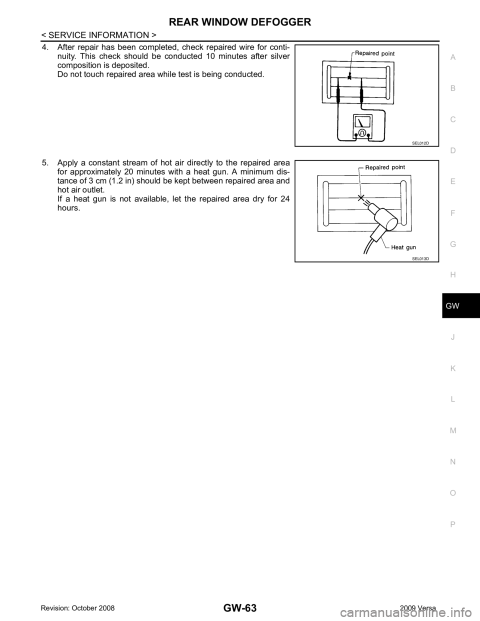
4. After repair has been completed, check repaired wire for conti-
nuity. This check should be conducted 10 minutes after silver
composition is deposited.
Do not touch repaired area while test is being conducted.
5. Apply a constant stream of hot air directly to the repaired area for approximately 20 minutes with a heat gun. A minimum dis-
tance of 3 cm (1.2 in) should be kept between repaired area and
hot air outlet.
If a heat gun is not available, let the repaired area dry for 24
hours.
Page 3367 of 4331
Page 3368 of 4331
GW
N
O P
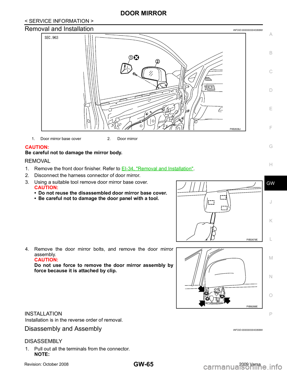
Removal and Installation
INFOID:0000000004306898
CAUTION:
Be careful not to damage the mirror body.
REMOVAL 1. Remove the front door finisher. Refer to EI-34, " Removal and Installation " .
2. Disconnect the harness connector of door mirror.
3. Using a suitable tool remove door mirror base cover. CAUTION:
• Do not reuse the disassembl ed door mirror base cover.
• Be careful not to damage the door panel with a tool.
4. Remove the door mirror bolts, and remove the door mirror assembly.
CAUTION:
Do not use force to remove the door mirror assembly by
force because it is attached by clip.
INSTALLATION Installation is in the reverse order of removal.
Disassembly and Assembly INFOID:0000000004306899
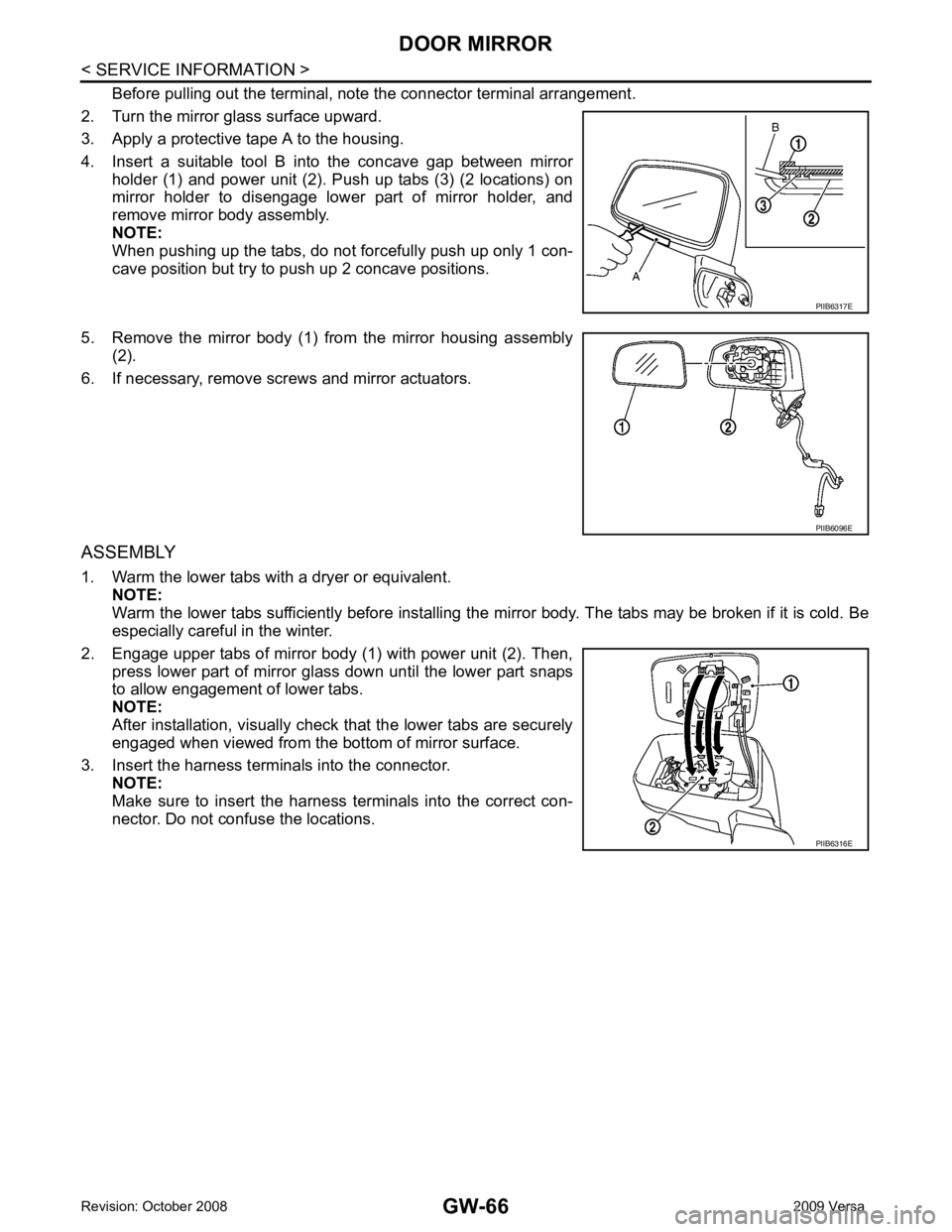
DISASSEMBLY 1. Pull out all the terminals from the connector. NOTE: PIIB6288E
Page 3369 of 4331
Page 3370 of 4331
GW
N
O P
INSIDE MIRROR
Removal and Installation INFOID:0000000004306900
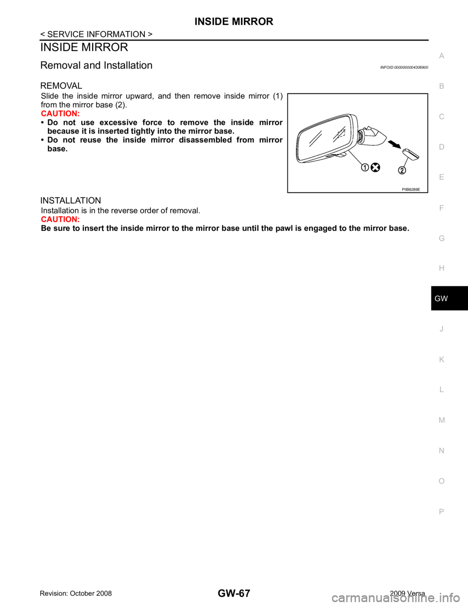
REMOVAL Slide the inside mirror upward, and then remove inside mirror (1)
from the mirror base (2).
CAUTION:
• Do not use excessive force to remove the inside mirror because it is inserted tigh tly into the mirror base.
• Do not reuse the inside mirror disassembled from mirror base.
INSTALLATION Installation is in the reverse order of removal.
CAUTION:
Be sure to insert the inside mirror to the mirro r base until the pawl is engaged to the mirror base.
Trending: towing, transmission, remove seats, length, high beam, tires, manual radio set
