sensor NISSAN LATIO 2009 Service Repair Manual
[x] Cancel search | Manufacturer: NISSAN, Model Year: 2009, Model line: LATIO, Model: NISSAN LATIO 2009Pages: 4331, PDF Size: 58.04 MB
Page 1936 of 4331

Diagnosis Procedure " .
Is malfunctioning part detected? Yes >> GO TO 11.
No >> GO TO 9. Symptom Matrix Chart " based on the confirmed symp-
tom in step 4, and determine the trouble diagnosis order based on possible causes and symptom.
>> GO TO 10. 25, " How to Perform Efficient Diagnosis for an Electrical Incident " .
Is malfunctioning part detected? Yes >> GO TO 11.
No >> Monitor input data from related sensors or check voltage of related ECM terminals using CON-
SULT-III. Refer to EC-597, " ECM Terminal and Reference Value " ,
EC-614, " CONSULT-III Refer-
ence Value in Data Monitor Mode " .
Emission-related Diagnostic Information " .
>> GO TO 12. NG (DTC*
1
is detected)>>GO TO 10.
NG (Symptom remains)>>GO TO 6.
OK >> 1. Before returning the vehicle to the customer, make sure to erase unnecessary DTC* 1
in ECM
and TCM (Transmission Control Module). (Refer to EC-542, " Emission-related Diagnostic
Information " and
AT-39, " OBD-II Diagnostic Trouble Code (DTC) " ,
CVT-209, " OBD-II Diag-
nostic Trouble Code (DTC) " .)
2. If the completion of SRT is needed, drive vehicl e under the specific driving pattern. Refer to
EC-542, " Emission-related Diagnostic Information " .
3. INSPECTION END
*1: Include 1st trip DTC.
*2: Include 1st trip freeze frame data.
DIAGNOSTIC WORKSHEET
Description
Page 1938 of 4331

DTC No. Detected items Engine operating condition in fail-safe mode
P0102
P0103 Mass air flow sensor circuit Engine speed will not rise more than 2,400 rpm due to the fuel cut.
Page 1939 of 4331

EC
NP
O
• When there is an open circuit on MIL circuit, the ECM c
annot warn the driver by lighting up MIL when there
is malfunction on engine control system.
Therefore, when electrical controlled throttle and pa rt of ECM related diagnoses are continuously detected
as NG for 5 trips, ECM warns the driver that engine control system malfunctions and MIL circuit is open by
means of operating fail-safe function.
The fail-safe function also operates when above diagnos es except MIL circuit are detected and demands the
driver to repair the malfunction.
Symptom Matrix Chart INFOID:0000000004537054
SYSTEM — BASIC ENGINE CONTROL SYSTEM P0117
P0118 Engine coolant temperature
sensor circuit Engine coolant temperature will be determined by ECM based on the following condi-
tion.
CONSULT-III displays the engine coolant temperature decided by ECM.
Condition Engine coolant temperature decided
(CONSULT-III display)
Just as ignition switch is turned ON
or START 40
°C (104 °F)
Approx. 4 minutes or more after
engine sarting. 80
°C (176 °F)
Except as shown above 40 - 80
°C (104 - 176 °F)
(Depends on the time)
When the fail-safe system for engine coolant temperature sensor is activated, the cool-
ing fan operates while engine is running.
P0122
P0123
P0222
P0223
P2135 Throttle position sensor The ECM controls the electric throttle control actuator in regulating the throttle opening
in order for the idle position to be within +10 degrees.
The ECM regulates the opening speed of the throttle valve to be slower than the normal
condition.
So, the acceleration will be poor.
P0643 Sensor power supply ECM stops the electric throttle control actuator control, throttle valve is maintained at a fixed opening (approx. 5 degrees) by the return spring.
P2100
P2103 Throttle control relay ECM stops the electric throttle control actuator control, throttle valve is maintained at a
fixed opening (approx. 5 degrees) by the return spring.
P2101 Electric throttle control func- tion ECM stops the electric throttle control actuator control, throttle valve is maintained at a
fixed opening (approx. 5 degrees) by the return spring.
P2118 Throttle control motor ECM stops the electric throttle control actuator control, throttle valve is maintained at a fixed opening (approx. 5 degrees) by the return spring.
P2119 Electric throttle control actu- ator (When electric throttle control actuator does not function properly due to the return
spring malfunction:)
ECM controls the electric throttle actuator by regulating the throttle opening around the
idle position. The engine speed will not rise more than 2,000 rpm.
(When throttle valve opening angle in fail-safe mode is not in specified range:)
ECM controls the electric throttle control ac tuator by regulating the throttle opening to
20 degrees or less.
(When ECM detects the throttle valve is stuck open:)
While the vehicle is driving, it slows down gradually by fuel cut. After the vehicle stops,
the engine stalls.
The engine can restart in N or P (A/T, CVT), Neutral (M/T) position, and engine speed
will not exceed 1,000 rpm or more.
P2122
P2123
P2127
P2128
P2138 Accelerator pedal position
sensor The ECM controls the electric throttle control actuator in regulating the throttle opening
in order for the idle position to be within +10 degrees.
The ECM regulates the opening speed of the throttle valve to be slower than the normal
condition.
So, the acceleration will be poor.
DTC No. Detected items Engine operating condition in fail-safe mode
Engine operating condition in fail-safe mode Engine speed will not rise more than 2,500 rpm due to the fuel cut
Page 1940 of 4331

Fuel pressure regulator system 3 3 4 4 4 4 4 4 4 4
EC-574Fuel injector circuit 1 1 2 3 2 2 2 2
EC-986Evaporative emission system 3 3 4 4 4 4 4 4 4 4
EC-527Air Positive crankcase ventilation sys-
tem 3 34 4 4 4 4 4 4 4 1
EC-538Incorrect idle speed adjustment 1 1 1 1 1
EC-566Electric throttle control actuator 1 1 2 3 3 2 2 2 2 2 2
EC-929 ,
EC-940 Ignition Incorrect ignition timing adjustment 3 3 1 1 1 1 1 1
EC-566Ignition circuit 1 1 2 2 2 2 2 2
EC-996Main power supply and ground circuit 2 2 3 3 3 3 3 2 3
EC-627Mass air flow sensor circuit
1
1 2 2
2 2 2 2 EC-655 ,
EC-663 Engine coolant temperature sensor circuit
33 3
EC-674 ,
EC-684 Air fuel ratio (A/F) sensor 1 circuit
EC-692 ,
EC-698 ,
EC-704 ,
EC-710 ,
EC-966 Throttle position sensor circuit
2 2EC-679 ,
EC-760 ,
EC-895 ,
EC-897 ,
EC-954 Accelerator pedal position sensor circuit 3 2 1
EC-874 ,
EC-942 ,
EC-947 ,
EC-959 Knock sensor circuit 2 3
EC-771Crankshaft position sensor (POS) circuit 2 2
EC-775Camshaft position sens
or (PHASE) circuit 3 2 EC-781Vehicle speed signal circuit 2 3 3 3
EC-866ECM 2 2 3 3 3 3 3 3 3 3 3
EC-872
Page 1941 of 4331

EC
NP
O
1 - 6: The numbers refer to the order of inspection.
(continued on next page)
SYSTEM — ENGINE MECHANICAL & OTHER Intake valve timing control solenoid valve cir-
cuit 3 2 1 3 2 2 3 3
EC-650Park/neutral position (P
NP) switch circuit 3 3 3 3 3 EC-879Refrigerant pressure sensor circuit 2 3 3 4
EC-1005Electrical load signal circuit 3
EC-984Air conditioner circuit 2 2 3 3 3 3 3 3 3 3 2
MTC-22ABS actuator and electric unit (control unit) 4
BRC-8SYMPTOM
Reference
pageHARD/NO START/RESTART (EXCP. HA)
ENGINE STALL
HESITATION/SURGING/FLAT SPOT
SPARK KNOCK/DETONATION
LACK OF POWER/POOR ACCELERATION
HIGH IDLE/LOW IDLE
ROUGH IDLE/HUNTING
IDLING VIBRATION
SLOW/NO RETURN TO IDLE
OVERHEATS/WATER TEMPERATURE HIGH
EXCESSIVE FUEL CONSUMPTION
EXCESSIVE OIL CONSUMPTION
BATTERY DEAD (UNDER CHARGE)
Warranty symptom code AA AB AC AD AE AF AG AH AJ AK AL AM HA SYMPTOM
Reference
page
HARD/NO START/RESTART (EXCP. HA)
ENGINE STALL
HESITATION/SURGING/FLAT SPOT
SPARK KNOCK/DETONATION
LACK OF POWER/POOR ACCELERATION
HIGH IDLE/LOW IDLE
ROUGH IDLE/HUNTING
IDLING VIBRATION
SLOW/NO RETURN TO IDLE
OVERHEATS/WATER TEMPERATURE HIGH
EXCESSIVE FUEL CONSUMPTION
EXCESSIVE OIL CONSUMPTION
BATTERY DEAD (UNDER CHARGE)
Warranty symptom code AA AB AC AD AE AF AG AH AJ AK AL AM HA
Fuel Fuel tank 5
5 FL-9Fuel piping 5 5 5 5 5 5
EM-156Vapor lock
—
Valve deposit 5 5 5 5 5 5 5 —
Poor fuel (Heavy weight gasoline,
Low octane) —
Page 1942 of 4331

Air cleaner
EM-139Air leakage from air duct
(Mass air flow sensor — electric
throttle control actuator) 5 5 5 5 EM-139Electric throttle control actuator
EM-141Air leakage from intake manifold/
Collector/Gasket EM-141Cranking Battery
1 1 1 1 1 1
11
SC-5 Generator circuit
SC-21Starter circuit 3
SC-9Signal plate 6
EM-199Park/neutral position (PNP)
switch 4 MT-54 ,
AT- 91 or
CVT-244 Engine Cylinder head
5 5 5 5 5 5 5 5 EM-185Cylinder head gasket 4 3
Cylinder block
6 6 6 6 6 6 6 6 4
EM-199 Piston
Piston ring
Connecting rod
Bearing
Crankshaft
Valve
mecha-
nism Timing chain
5 5 5 5 5 5 5 5 EM-160Camshaft
EM-170Intake valve timing control
EM-170Intake valve
3EM-185 Exhaust valve
Exhaust Exhaust manifold/Tube/Muffler/ Gasket 5 5 5 5 5 5 5 5 EM-144 ,
EX-9 Three way catalyst
Lubrica-
tion Oil pan/Oil strainer/Oil pump/Oil
filter/Oil gallery 5 5 5 5 5 5 5 5 EM-147 ,
LU-19 Oil level (Low)/Filthy oil
LU-16SYMPTOM
Reference
pageHARD/NO START/RESTART (EXCP. HA)
ENGINE STALL
HESITATION/SURGING/FLAT SPOT
SPARK KNOCK/DETONATION
LACK OF POWER/POOR ACCELERATION
HIGH IDLE/LOW IDLE
ROUGH IDLE/HUNTING
IDLING VIBRATION
SLOW/NO RETURN TO IDLE
OVERHEATS/WATER TEMPERATURE HIGH
EXCESSIVE FUEL CONSUMPTION
EXCESSIVE OIL CONSUMPTION
BATTERY DEAD (UNDER CHARGE)
Warranty symptom code AA AB AC AD AE AF AG AH AJ AK AL AM HA
Page 1945 of 4331

EC
NP
O
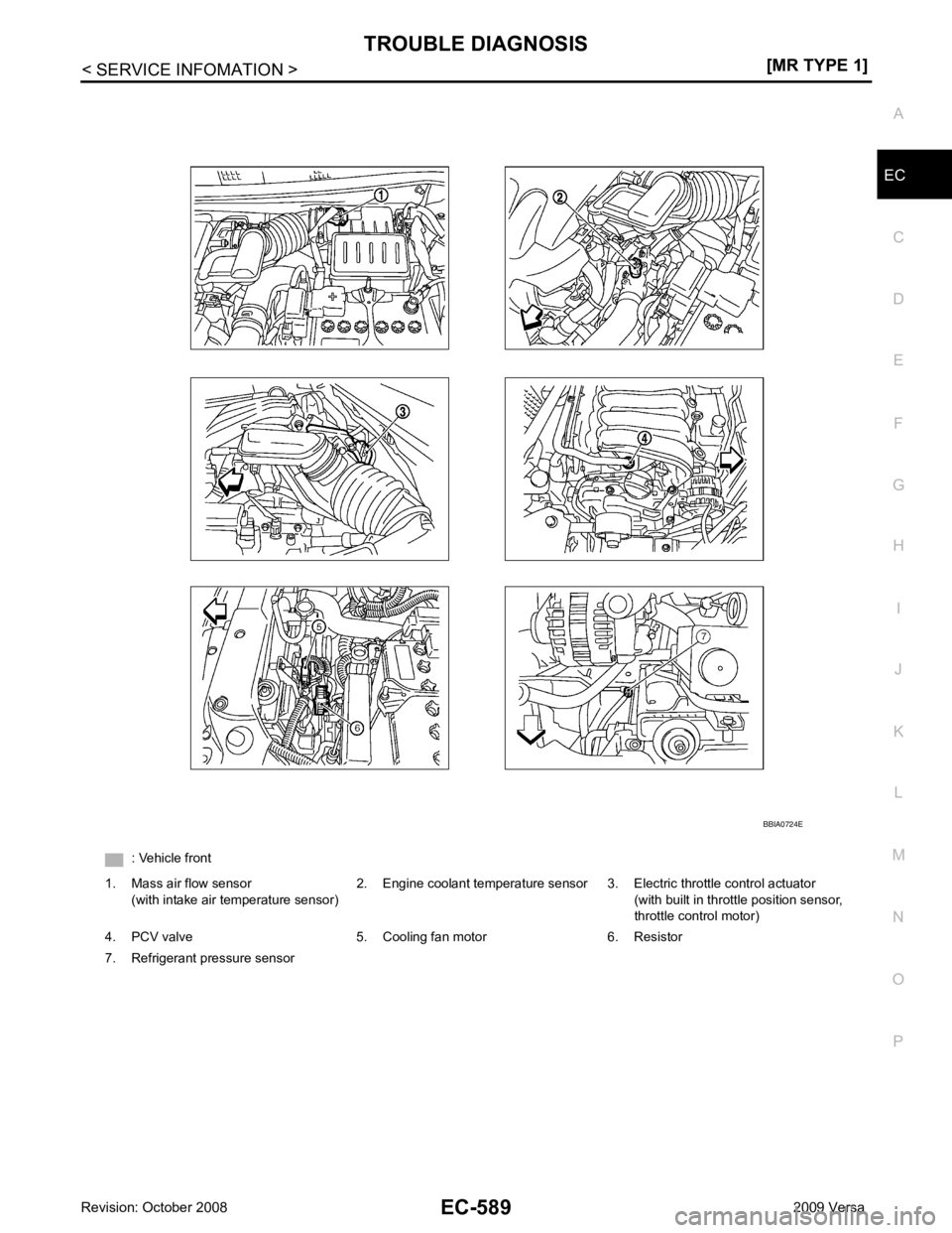
: Vehicle front
1. Mass air flow sensor (with intake air temperature sensor) 2. Engine coolant temperature sensor 3. Electric throttle control actuator
(with built in throttle position sensor,
throttle control motor)
4. PCV valve 5. Cooling fan motor 6. Resistor
7. Refrigerant pressure sensor
Page 1947 of 4331

EC
NP
O
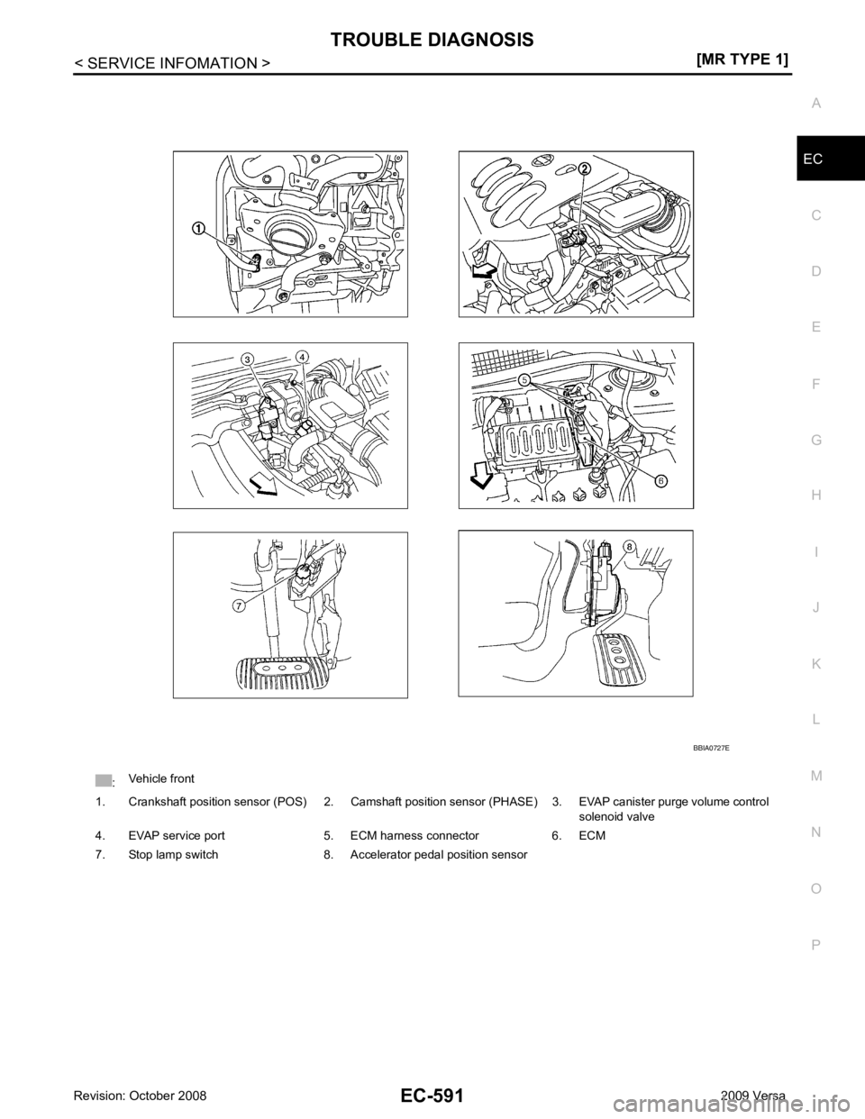
:
Vehicle front
1. Crankshaft position sensor (POS) 2. Camshaft position sensor (PHASE) 3. EVAP canister purge volume control solenoid valve
4. EVAP service port 5. ECM harness connector 6. ECM
7. Stop lamp switch 8. Accelerator pedal position sensor
Page 1953 of 4331
![NISSAN LATIO 2009 Service Repair Manual TROUBLE DIAGNOSIS
EC-597
< SERVICE INFOMATION >
[MR TYPE 1] C
D E
F
G H
I
J
K L
M A EC
NP
O
ECM Harness Connector Terminal Layout
INFOID:0000000004537058
ECM Terminal and Reference Value INFOID:000000 NISSAN LATIO 2009 Service Repair Manual TROUBLE DIAGNOSIS
EC-597
< SERVICE INFOMATION >
[MR TYPE 1] C
D E
F
G H
I
J
K L
M A EC
NP
O
ECM Harness Connector Terminal Layout
INFOID:0000000004537058
ECM Terminal and Reference Value INFOID:000000](/img/5/57359/w960_57359-1952.png)
TROUBLE DIAGNOSIS
EC-597
< SERVICE INFOMATION >
[MR TYPE 1] C
D E
F
G H
I
J
K L
M A EC
NP
O
ECM Harness Connector Terminal Layout
INFOID:0000000004537058
ECM Terminal and Reference Value INFOID:0000000004537059
PREPARATION 1. ECM (1) is located in the engine room left side near battery. • : Vehicle front
ECM INSPECTION TABLE Specification data are reference values and are measured between each terminal and ground.
Pulse signal is measured by CONSULT-III.
CAUTION:
Do not use ECM ground terminals wh en measuring input/output voltage. Doing so may result in dam-
age to the ECMs transistor. Use a ground ot her than ECM terminals, such as the ground. PBIA9221J
PBIB2959E
TERMI-
NAL NO. WIRE
COLOR ITEM CONDITION DATA (DC Voltage)
1 L Throttle control motor
(Open) [Ignition switch: ON]
• Engine stopped
• Shift lever: D (A/T, CVT), 1st (M/T)
• Accelerator pedal: Fully depressed Approximately 3.2V
2 SB Throttle contro
l motor power
supply [Ignition switch: ON] BATTERY VOLTAGE
(11 - 14V)
3 G A/F sensor 1 heater [Engine is running]
• Warm-up condition
• Idle speed
(More than 140 seconds after starting en-
gine) Approximately 2.9 - 8.8V PBIA8150J
PBIA8148J
Page 1957 of 4331
![NISSAN LATIO 2009 Service Repair Manual EC
NP
O
50 W Heated oxygen sensor 2
[Engine is running]
• Revving engine from idle to 3,000 rpm quickly after the following conditions are
met.
- Engine: After warming up
- Keeping the engine spee NISSAN LATIO 2009 Service Repair Manual EC
NP
O
50 W Heated oxygen sensor 2
[Engine is running]
• Revving engine from idle to 3,000 rpm quickly after the following conditions are
met.
- Engine: After warming up
- Keeping the engine spee](/img/5/57359/w960_57359-1956.png)
EC
NP
O
50 W Heated oxygen sensor 2
[Engine is running]
• Revving engine from idle to 3,000 rpm quickly after the following conditions are
met.
- Engine: After warming up
- Keeping the engine speed between 3,500
and 4,000 rpm for 1 minute and at idle for 1
minute under no load. 0 - Approximately 1.0V
51 O Sensor ground
(EVAP control system pres-
sure sensor) [Engine is running]
• Warm-up condition
• Idle speed Approximately 0V
52 LG Sensor ground
(Mass air flow sensor) [Engine is running]
• Warm-up condition
• Idle speed Approximately 0V
53 B A/F sensor 1 [Ignition switch: ON]Approximately 2.2V
55 O Sensor ground
(Intake air temperature sen-
sor) [Engine is running]
• Warm-up condition
• Idle speed Approximately 0V
59 O Sensor ground
(Heated oxygen sensor 2) [Engine is running]
• Warm-up condition
• Idle speed Approximately 0V
61 W Crankshaft position sensor
(POS) [Engine is running]
• Warm-up condition
• Idle speed NOTE:
The pulse cycle changes depending on rpm
at idle. Approximately 4.0V
[Engine is running]
• Engine speed: 2,000 rpm Approximately 4.0V
62 R Sensor ground
[Crankshaft position sensor
(POS)] [Engine is running]
• Warm-up condition
• Idle speed Approximately 0V
63 BR Sensor ground
[Camshaft position sensor
(PHASE)] [Engine is running]
• Warm-up condition
• Idle speed Approximately 0V
TERMI-
NAL
NO. WIRE
COLOR ITEM CONDITION DATA (DC Voltage)