sensor NISSAN LATIO 2009 Service Workshop Manual
[x] Cancel search | Manufacturer: NISSAN, Model Year: 2009, Model line: LATIO, Model: NISSAN LATIO 2009Pages: 4331, PDF Size: 58.04 MB
Page 198 of 4331
AT
N
O P Control Valve Assembly and Accumulators " .
2. Check the following items:
- Shift valve B
- Shift solenoid valve B
- Pilot valve
- Pilot filter
OK or NG OK >> GO TO 8.
NG >> Repair or replace damaged parts. Cruise Test - Part 1 " and
AT-61, " Cruise Test - Part 2 " .
OK or NG OK >>
INSPECTION END
NG >> GO TO 9. TCM Terminal and Reference Value " .
2. If NG, recheck TCM pin terminals for dam age or loose connection with harness connector.
OK or NG OK >>
INSPECTION END
NG >> Repair or replace damaged parts.
A/T Does Not Shift: D 3→ D 4 INFOID:0000000004305482
SYMPTOM: • A/T does not shift from D 3 to D 4 at the specified speed on “Cruise Test — Part 1” and “Cruise Test
— Part 2”.
• A/T must be warm before D 3
to D 4 shift will occur.
DIAGNOSTIC PROCEDURE Check at Idle " and
AT-58, " Cruise Test - Part 1 " .
Are “ Vehicle Does Not Creep Forward in “ D ” , “ 2 ” or “ 1 ” Position ” and “ Vehicle Cannot Be Started from D OK?
YES >> GO TO 2.
NO >> Go to AT-187, " Vehicle Does Not Creep Forward in "D", "2" or "1" Position " and
AT-188, " Vehicle
Cannot Be Started from D .
CONSULT-III Functi
on (TRANSMISSION) " or
AT-83, " Diagnosis Pro-
cedure without CONSULT-III " .
Is any malfunction detected by self-diagnostic results? YES >> Check the malfuncti
oning system. Refer to AT-79, " CONSULT-III Functi
on (TRANSMISSION) " or
AT-83, " Diagnosis Procedure without CONSULT-III " .
NO >> GO TO 3. Description " (HR16DE),
EC-959, " Component
Description " (MR Type 1) or
EC-1481, " Component Description " (MR Type 2).
OK or NG OK >> GO TO 4.
NG >> Repair or replace accelerator pedal position sensor. Component " .
Page 200 of 4331
AT
N
O P
Is any malfunction detected by self-diagnostic results? YES >> Check the malfuncti
oning system. Refer to AT-79, " CONSULT-III Functi
on (TRANSMISSION) " or
AT-83, " Diagnosis Procedure without CONSULT-III " .
NO >> GO TO 2. Description " (HR16DE),
EC-959, " Component
Description " (MR Type 1) or
EC-1481, " Component Description " (MR Type 2).
OK or NG OK >> GO TO 3.
NG >> Repair or replace accelerator pedal position sensor. Control Valve Assembly and Accumulators " .
2. Check following items:
- Torque converter clutch control valve
- Torque converter clutch solenoid valve
- Torque converter relief valve
- Pilot valve
- Pilot filter
3. Disassemble A/T. Refer to AT-256, " Disassembly " .
4. Check the following items:
- Torque converter. Refer to AT-256, " Disassembly " .
OK or NG OK >> GO TO 4.
NG >> Repair or replace damaged parts. Cruise Test - Part 1 " .
OK or NG OK >>
INSPECTION END
NG >> GO TO 5. TCM Terminal and Reference Value " .
2. If NG, recheck TCM pin terminals for dam age or loose connection with harness connector.
OK or NG OK >>
INSPECTION END
NG >> Repair or replace damaged parts.
A/T Does Not Hold Lock-up Condition INFOID:0000000004305484
SYMPTOM: A/T does not hold lock-up condition for more than 30 second s on “Cruise Test — Part 1”.
DIAGNOSTIC PROCEDURE CONSULT-III Functi
on (TRANSMISSION) " or
AT-83, " Diagnosis Pro-
cedure without CONSULT-III " .
Is any malfunction detected by self-diagnostic results? YES >> Check the malfuncti
oning system. Refer to AT-79, " CONSULT-III Functi
on (TRANSMISSION) " or
AT-83, " Diagnosis Procedure without CONSULT-III " .
NO >> GO TO 2. Component " .
2. Check A/T fluid condition. Refer to AT-51, " Inspections Before Trouble Diagnosis " .
Page 202 of 4331
AT
N
O P
Check again. Refer to
AT-58, " Cruise Test - Part 1 " .
OK or NG OK >>
INSPECTION END
NG >> GO TO 3. TCM Terminal and Reference Value " .
2. If NG, recheck TCM pin terminals for dam age or loose connection with harness connector.
OK or NG OK >>
INSPECTION END
NG >> Repair or replace damaged parts.
Engine Speed Does Not Return to Idle (Light Braking D4→ D 3) INFOID:0000000004305486
SYMPTOM: Engine speed does not smoothly return to idle when A/T shifts from D4 to D 3 on “Cruise Test — Part
1”.
DIAGNOSTIC PROCEDURE CONSULT-III Functi
on (TRANSMISSION) " or
AT-83, " Diagnosis Pro-
cedure without CONSULT-III " .
Is any malfunction detected by self-diagnostic results? YES >> Check the malfuncti
oning system. Refer to AT-79, " CONSULT-III Functi
on (TRANSMISSION) " or
AT-83, " Diagnosis Procedure without CONSULT-III " .
NO >> GO TO 2. Description " (HR16DE),
EC-959, " Component
Description " (MR Type 1) or
EC-1481, " Component Description " (MR Type 2).
OK or NG OK >> GO TO 3.
NG >> Repair or replace accelerator pedal position sensor. Component " .
2. Check A/T fluid condition. Refer to AT-51, " Inspections Before Trouble Diagnosis " .
OK or NG OK >> GO TO 5.
NG >> GO TO 4. Control Valve Assembly and Accumulators " .
2. Check the following items:
- Overrun clutch control valve
- Overrun clutch reducing valve
- Overrun clutch solenoid valve
3. Disassemble A/T. Refer to AT-256, " Disassembly " .
4. Check the following items:
- Overrun clutch assembly. Refer to AT-306, " Forward and Overrun Clutches " .
OK or NG OK >> GO TO 6.
NG >> Repair or replace damaged parts. Control Valve Assembly and Accumulators " .
2. Check the following items:
Page 206 of 4331
TROUBLE DIAGNOSIS FOR SYMPTOMS
AT-201
< SERVICE INFORMATION >
D
E
F
G H
I
J
K L
M A
B AT
N
O P
OK >> GO TO 3
NG >> Check PNP switch. Refer to AT-176, " Component Inspection " .
2.
CHECK PNP SWITCH CIRCUIT
Without CONSULT-III
1. Turn ignition switch ON. (Do not start engine.)
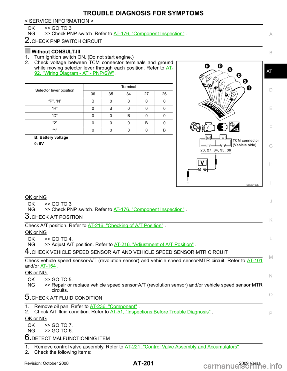
2. Check voltage between TCM connector terminals and ground
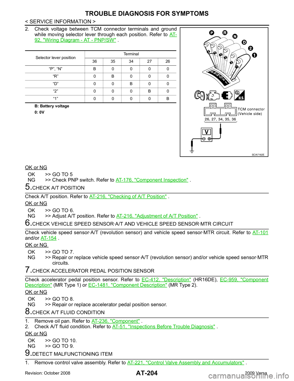
while moving selector lever through each position. Refer to AT-92, " Wiring Diagram - AT - PNP/SW " .
B: Battery voltage
0: 0V
OK or NG OK >> GO TO 3
NG >> Check PNP switch. Refer to AT-176, " Component Inspection " .
3.
CHECK A/T POSITION
Check A/T position. Refer to AT-216, " Checking of A/T Position " .
OK or NG OK >> GO TO 4.
NG >> Adjust A/T position. Refer to AT-216, " Adjustment of A/T Position " .
4.
CHECK VEHICLE SPEED SENS OR·A/T AND VEHICLE SPEED SENSOR·MTR CIRCUIT
Check vehicle speed sensor·A/T (re volution sensor) and vehicle speed sensor·MTR circuit. Refer to AT-101and/or
AT-154 .
OK or NG OK >> GO TO 5.
NG >> Repair or replace vehicle speed sensor·A/T (revolution sensor) and/or vehicle speed sensor·MTR
circuits. 5.
CHECK A/T FLUID CONDITION
1. Remove oil pan. Refer to AT-236, " Component " .
2. Check A/T fluid condition. Refer to AT-51, " Inspections Before Trouble Diagnosis " .
OK or NG OK >> GO TO 7.
NG >> GO TO 6. 6.
DETECT MALFUNCTIONING ITEM
1. Remove control valve assembly. Refer to AT-221, " Control Valve Assembly and Accumulators " .
2. Check the following items: Selector lever position
Terminal
36 35 34 27 26
“P”, “N” B 0 0 0 0 “R” 0 B 0 0 0
“D” 0 0 B 0 0 “2” 0 0 0 B 0
“1” 0 0 0 0 B SCIA7162E
Page 209 of 4331
AT-204< SERVICE INFORMATION >
TROUBLE DIAGNOSIS FOR SYMPTOMS
2. Check voltage between TCM connector terminals and ground while moving selector lever through each position. Refer to AT-92, " Wiring Diagram - AT - PNP/SW " .
B: Battery voltage
0: 0V
OK or NG OK >> GO TO 5
NG >> Check PNP switch. Refer to AT-176, " Component Inspection " .
5.
CHECK A/T POSITION
Check A/T position. Refer to AT-216, " Checking of A/T Position " .
OK or NG OK >> GO TO 6.
NG >> Adjust A/T position. Refer to AT-216, " Adjustment of A/T Position " .
6.
CHECK VEHICLE SPEED SENSOR·A/T A ND VEHICLE SPEED SENSOR·MTR CIRCUIT
Check vehicle speed sensor·A/T (revolution senso r) and vehicle speed sensor·MTR circuit. Refer to AT-101and/or
AT-154 .
OK or NG OK >> GO TO 7.
NG >> Repair or replace vehicle speed sensor·A/T (revolution sensor) and/or vehicle speed sensor·MTR
circuits. 7.
CHECK ACCELERATOR PEDAL POSITION SENSOR
Check accelerator pedal position sensor. Refer to EC-412, " Description " (HR16DE),
EC-959, " Component
Description " (MR Type 1) or
EC-1481, " Component Description " (MR Type 2).
OK or NG OK >> GO TO 8.
NG >> Repair or replace accelerator pedal position sensor. 8.
CHECK A/T FLUID CONDITION
1. Remove oil pan. Refer to AT-236, " Component " .
2. Check A/T fluid condition. Refer to AT-51, " Inspections Before Trouble Diagnosis " .
OK or NG OK >> GO TO 10.
NG >> GO TO 9. 9.
DETECT MALFUNCTIONING ITEM
1. Remove control valve assembly. Refer to AT-221, " Control Valve Assembly and Accumulators " .
Selector lever position
Terminal
36 35 34 27 26
“P”, “N” B 0 0 0 0 “R” 0 B 0 0 0
“D” 0 0 B 0 0 “2” 0 0 0 B 0
“1” 0 0 0 0 B SCIA7162E
Page 231 of 4331
![NISSAN LATIO 2009 Service Workshop Manual " Control Device Removal and Installation " .
4. Loosen PNP switch bolts. :Bolt
5. Insert the pin (3) [4 mm (0.16 in) dia.] straight into manual shaft (1) adjustment hole.
6. Rotate PNP switch (2) NISSAN LATIO 2009 Service Workshop Manual " Control Device Removal and Installation " .
4. Loosen PNP switch bolts. :Bolt
5. Insert the pin (3) [4 mm (0.16 in) dia.] straight into manual shaft (1) adjustment hole.
6. Rotate PNP switch (2)](/img/5/57359/w960_57359-230.png)
" Control Device Removal and Installation " .
4. Loosen PNP switch bolts. :Bolt
5. Insert the pin (3) [4 mm (0.16 in) dia.] straight into manual shaft (1) adjustment hole.
6. Rotate PNP switch (2) until the pin (3) can also be inserted straight into hole in PNP switch (2).
7. Tighten PNP switch bolts to the specified torque. Refer to "COMPONENTS".
8. Remove the pin (3) from adjustment hole after adjusting PNP switch (2).
9. Install the control cable. Refer to AT-212, " Control Device Removal and Installation " .
10. Adjust and check A/T position. Refer to AT-216, " Adjustment of A/T Position " and
AT-216, " Checking of A/
T Position " .
11. Check continuity of PNP switch (2). Refer to AT-176, " Component Inspection " .
12. Install the air duct (inlet). Refer to EM-139 .
Revolution Sensor INFOID:0000000004305505
COMPONENTS
REMOVAL AND INSTALLATION
Removal
1. Disconnect the battery negative terminal.
2. Remove air duct (inlet), air duct and air cleaner case. Refer to EM-139, " Component " .
Page 232 of 4331
AT
N
O P
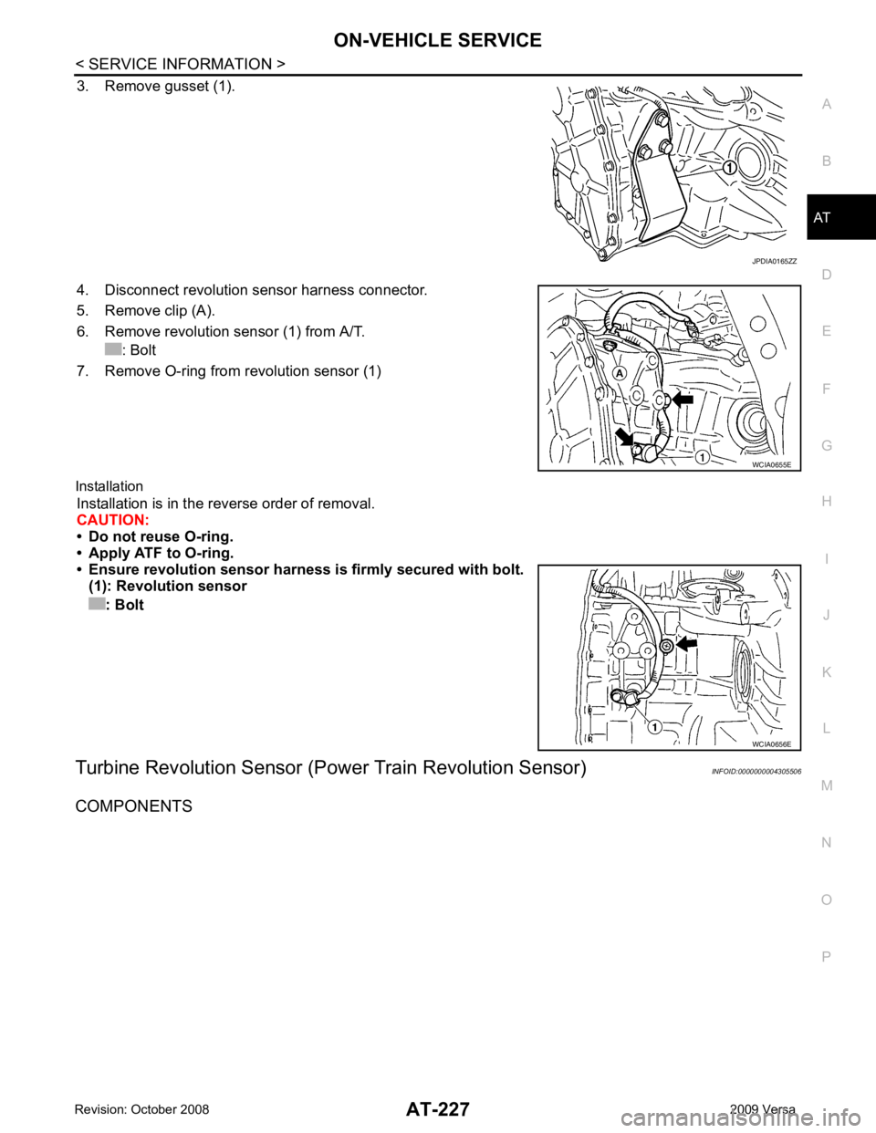
3. Remove gusset (1).
4. Disconnect revolution sensor harness connector.
5. Remove clip (A).
6. Remove revolution sensor (1) from A/T. : Bolt
7. Remove O-ring from revolution sensor (1)
Installation Installation is in the reverse order of removal.
CAUTION:
• Do not reuse O-ring.
• Apply ATF to O-ring.
• Ensure revolution sensor harn ess is firmly secured with bolt.
(1): Revolution sensor
: Bolt
Turbine Revolution Sensor (Power Train Revolution Sensor) INFOID:0000000004305506
COMPONENTS
Page 233 of 4331
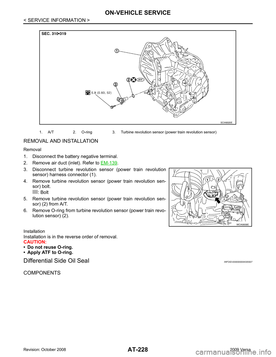
.
3. Disconnect turbine revolution sensor (power train revolution sensor) harness connector (1).
4. Remove turbine revolution sensor (power train revolution sen- sor) bolt.
: Bolt
5. Remove turbine revolution sensor (power train revolution sen- sor) (2) from A/T.
6. Remove O-ring from turbine revolution sensor (power train revo- lution sensor) (2).
Installation
Installation is in the reverse order of removal.
CAUTION:
• Do not reuse O-ring.
• Apply ATF to O-ring.
Differential Side Oil Seal INFOID:0000000004305507
COMPONENTS 1. A/T 2. O-ring 3. Turbine revolution sensor (power train revolution sensor)
Page 238 of 4331
AT
N
O P
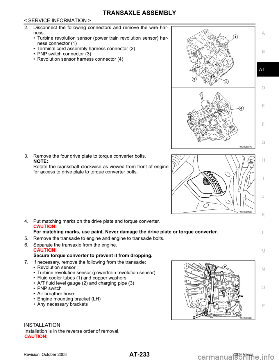
2. Disconnect the following connectors and remove the wire har-
ness.
• Turbine revolution sensor (power train revolution sensor) har-
ness connector (1)
• Terminal cord assembly harness connector (2)
• PNP switch connector (3)
• Revolution sensor harness connector (4)
3. Remove the four drive plate to torque converter bolts. NOTE:
Rotate the crankshaft clockwise as viewed from front of engine
for access to drive plate to torque converter bolts.
4. Put matching marks on the drive plate and torque converter. CAUTION:
For matching marks, use paint. Never dama ge the drive plate or torque converter.
5. Remove the transaxle to engine and engine to transaxle bolts.
6. Separate the transaxle from the engine. CAUTION:
Secure torque converter to prevent it from dropping.
7. If necessary, remove the following from the transaxle: • Revolution sensor
• Turbine revolution sensor (powertrain revolution sensor)
• Fluid cooler tubes (1) and copper washers
• A/T fluid level gauge (2) and charging pipe (3)
• PNP switch
• Air breather hose
• Engine mounting bracket (LH)
• Any necessary brackets
INSTALLATION Installation is in the reverse order of removal.
CAUTION: WCIA0616E
WCIA0648E
Page 254 of 4331
AT
N
O P
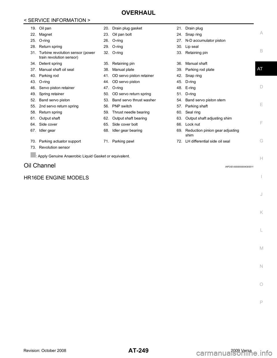
Oil Channel
INFOID:0000000004305511
HR16DE ENGINE MODELS 19. Oil pan 20. Drain plug gasket 21. Drain plug
22. Magnet 23. Oil pan bolt 24. Snap ring
25. O-ring 26. O-ring 27. N-D accumulator piston
28. Return spring 29. O-ring 30. Lip seal
31. Turbine revolution sensor (power train revolution sensor) 32. O-ring 33. Retaining pin
34. Detent spring 35. Retaining pin 36. Manual shaft
37. Manual shaft oil seal 38. Manual plate 39. Parking rod plate
40. Parking rod 41. OD servo piston retainer 42. Snap ring
43. O-ring 44. OD servo piston 45. D-ring
46. Servo piston retainer 47. O-ring 48. E-ring
49. Spring retainer 50. OD servo return spring 51. D-ring
52. Band servo piston 53. Band servo thrust washer 54. Band servo piston stem
55. 2nd servo return spring 56. PNP switch 57. Parking shaft
58. Return spring 59. Thrust needle bearing 60. Seal ring
61. Output shaft 62. Output shaft bearing 63. Output shaft adjusting shim
64. Side cover 65. Side cover bolt 66. Lock nut
67. Idler gear 68. Idler gear bearing 69. Reduction pinion gear adjusting shim
70. Parking actuator support 71. Parking pawl 72. LH differential side oil seal
73. Revolution sensor
: Apply Genuine Anaerobic Liquid Gasket or equivalent.