sensor NISSAN LATIO 2009 Service Manual Online
[x] Cancel search | Manufacturer: NISSAN, Model Year: 2009, Model line: LATIO, Model: NISSAN LATIO 2009Pages: 4331, PDF Size: 58.04 MB
Page 693 of 4331
BL-232< SERVICE INFORMATION >
VEHICLE SECURITY (T
HEFT WARNING) SYSTEM
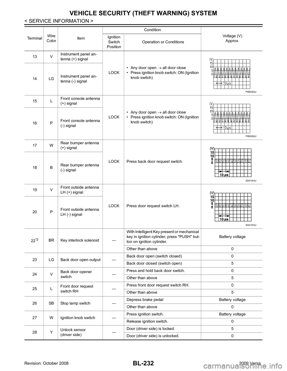
13 V Instrument panel an-
tenna (+) signal
LOCK• Any door open
→ all door close
• Press ignition knob switch: ON (Ignition knob switch)
14 LG Instrument panel an-
tenna (-) signal
15 L Front console antenna
(+) signal
LOCK• Any door open
→ all door close
• Press ignition knob switch: ON (Ignition knob switch)
16 P Front console antenna
(-) signal
17 W Rear bumper antenna
(+) signal
LOCK Press back door request switch.
18 B Rear bumper antenna
(-) signal
19 V Front outside antenna
LH (+) signal
LOCK Press door request switch LH.
20 P Front outside antenna
LH (-) signal
22 *2
BR Key interlock solenoid — With Intelligent Key present or mechanical
key in ignition cylinder, press "PUSH" but-
ton on ignition cylinder. Battery voltage
Other than above 0
23 LG Back door open output — Back door open (switch closed) 0
Back door closed (switch open) 5
24 V Back door opener
switch —Press and hold back door switch. 0
Other than above 5
25 L Front door request
switch RH —Press front door request switch RH. 0
Other than above 5
26 SB Stop lamp switch — Depress brake pedal Battery voltage
Other than above 0
27 W Ignition knob switch — Press ignition switch. Battery voltage
Release ignition switch. 0
28 Y Unlock sensor
(driver side) —Door (driver si
de) is locked. 5
Door (driver side ) is unlocked. 0
Terminal
Wire
Color Item Condition
Voltage (V)Approx.
Ignition
Switch
Position Operation or Conditions PIIB5502J
PIIB5502J
SIIA1910J
SIIA1910J
Page 841 of 4331

BRC
N
O P
CONTENTS
BRAKE CONTROL SYSTEM
ABS
SERVICE INFORMATION .. ..........................
2
PRECAUTIONS .............................................. .....2
Precaution for Supplemental Restraint System
(SRS) "AIR BAG" and "SEAT BELT PRE-TEN-
SIONER" ............................................................. ......
2
Precaution for Brake System .............................. ......2
Precaution for Brake Cont rol .....................................3
Precaution for CAN System ................................ ......3
PREPARATION .............................................. .....4
Special Service Tool ........................................... ......4
Commercial Service Tool .................................... ......4
SYSTEM DESCRIPTION ................................ .....5
System Component ............................................. ......5
ABS Function ...................................................... ......5
EBD Function ...................................................... ......5
Fail-Safe Function ............................................... ......5
Hydraulic Circuit Diagram .........................................6
CAN COMMUNICATION ................................ .....7
System Description ............................................. ......7
TROUBLE DIAGNOSIS ................................. .....8
How to Perform Trouble Diagnosis for Quick and
Accurate Repair ........... .............................................
8
Component Parts and Harness Connector Loca-
tion ...................................................................... ....
11
Schematic ........................................................... ....12
Wiring Diagram - ABS - ... ........................................13 Basic Inspection ..................................................
....16
Warning Lamp and Indicator Timing .................... ....17
Control Unit Input/Output Signal Standard .......... ....17
CONSULT-III Function ( ABS) ..................................18
TROUBLE DIAGNOSIS FOR SELF-DIAG-
NOSTIC ITEMS ................................................. 24
Wheel Sensor System ......................................... ....24
ABS Control Unit Inspection ................................ ....25
Solenoid Valve System Inspection ...................... ....25
Actuator Motor, Motor Re lay, and Circuit Inspec-
tion ....................................................................... ....
26
ABS Control Unit Power and Ground Systems In-
spection ............................................................... ....
27
CAN Communication System Inspection ............. ....28
TROUBLE DIAGNOSES FOR SYMPTOMS ..... 29
ABS Works Frequently ........................................ ....29
Unexpected Pedal Action .................................... ....29
Long Stopping Distance ...................................... ....30
ABS Does Not Work ............................................ ....30
Pedal Vibration or ABS Op eration Noise .................30
WHEEL SENSORS ........................................... 32
Removal and Installation ..................................... ....32
SENSOR ROTOR .............................................. 34
Removal and Installation ..................................... ....34
ACTUATOR AND ELECTRIC UNIT (ASSEM-
BLY) .................................................................. 35
Removal and Installation ..................................... ....35
Page 842 of 4331
![NISSAN LATIO 2009 Service Manual Online BRC-2< SERVICE INFORMATION >
[ABS]
PRECAUTIONS
SERVICE INFORMATION
PRECAUTIONS
Precaution for Supplemental Restraint Syst em (SRS) "AIR BAG" and "SEAT BELT
PRE-TENSIONER" INFOID:0000000004784402
The NISSAN LATIO 2009 Service Manual Online BRC-2< SERVICE INFORMATION >
[ABS]
PRECAUTIONS
SERVICE INFORMATION
PRECAUTIONS
Precaution for Supplemental Restraint Syst em (SRS) "AIR BAG" and "SEAT BELT
PRE-TENSIONER" INFOID:0000000004784402
The](/img/5/57359/w960_57359-841.png)
BRC-2< SERVICE INFORMATION >
[ABS]
PRECAUTIONS
SERVICE INFORMATION
PRECAUTIONS
Precaution for Supplemental Restraint Syst em (SRS) "AIR BAG" and "SEAT BELT
PRE-TENSIONER" INFOID:0000000004784402
The Supplemental Restraint System such as “A IR BAG” and “SEAT BELT PRE-TENSIONER”, used along
with a front seat belt, helps to reduce the risk or severi ty of injury to the driver and front passenger for certain
types of collision. This system includes seat belt switch inputs and dual stage front air bag modules. The SRS
system uses the seat belt switches to determine the front air bag deployment, and may only deploy one front
air bag, depending on the severity of a collision and w hether the front occupants are belted or unbelted.
Information necessary to service the system safely is included in the SRS and SB section of this Service Man-
ual.
WARNING:
• To avoid rendering the SRS inopera tive, which could increase the risk of personal injury or death in
the event of a collision which would result in air bag inflation, all maintenance must be performed by
an authorized NISS AN/INFINITI dealer.
• Improper maintenance, including incorrect removal and installation of the SRS can lead to personal
injury caused by unintent ional activation of the system. For re moval of Spiral Cable and Air Bag
Module, see the SRS section.
• Do not use electrical test equipmen t on any circuit related to the SRS unless instructed to in this
Service Manual. SRS wiring harn esses can be identified by yellow and/or orange harnesses or har-
ness connectors.
PRECAUTIONS WHEN USING POWER TOOLS (AIR OR ELECTRIC) AND HAMMERS
WARNING:
• When working near the Airbag Diagnosis Sensor Unit or other Airbag System sensors with the Igni-
tion ON or engine running, DO NOT use air or electri c power tools or strike near the sensor(s) with a
hammer. Heavy vibration could activate the sensor( s) and deploy the air bag(s), possibly causing
serious injury.
• When using air or electric power tools or hammers , always switch the Ignition OFF, disconnect the
battery, and wait at least 3 minu tes before performing any service.
Precaution for Brake System INFOID:0000000004307251
CAUTION:
• Refer to MA-14 for recommended brake fluid.
• Never reuse drained brake fluid.
• Be careful not to splash brake fluid on painted areas; it may cause paint damage. If brake fluid is
splashed on painted areas, wash it away with water immediately.
• To clean or wash all parts of master cylin der and disc brake caliper, use clean brake fluid.
• Never use mineral oils such as gasoline or kerosene. They will ruin rubber parts of the hydraulic sys-
tem.
• Use flare nut wrench when re moving and installing brake
tube.
• If a brake fluid leak is found, the part must be disassembled
without fail. Then it has to be replaced with a new one if a
defect exists.
• Turn the ignition switch OFF an d remove the connector of the
ABS actuator and electric unit (c ontrol unit) or the battery ter-
minal before performing the work.
• Always torque brake lines when installing.
• Burnish the brake contact surf aces after refinishing or replac-
ing rotors, after replacing pads, or if a soft pedal occurs at
very low mileage. Refer to BR-32, " Brake Burnishing Proce-
dure " .
WARNING:
• Clean brake pads and shoes with a waste cloth, then wipe with a dust collector. SBR686C
Page 851 of 4331
BRC
N
O P
Component Parts and Har
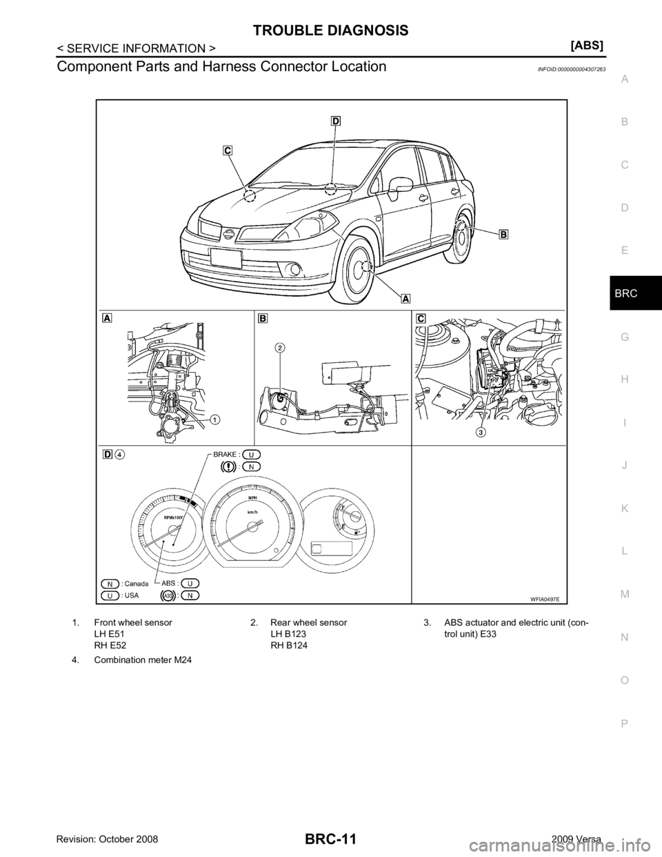
ness Connector Location INFOID:0000000004307263
1. Front wheel sensor LH E51
RH E52 2. Rear wheel sensor
LH B123
RH B124 3. ABS actuator and electric unit (con-
trol unit) E33
4. Combination meter M24
Page 858 of 4331
Wheel Sensor
System "
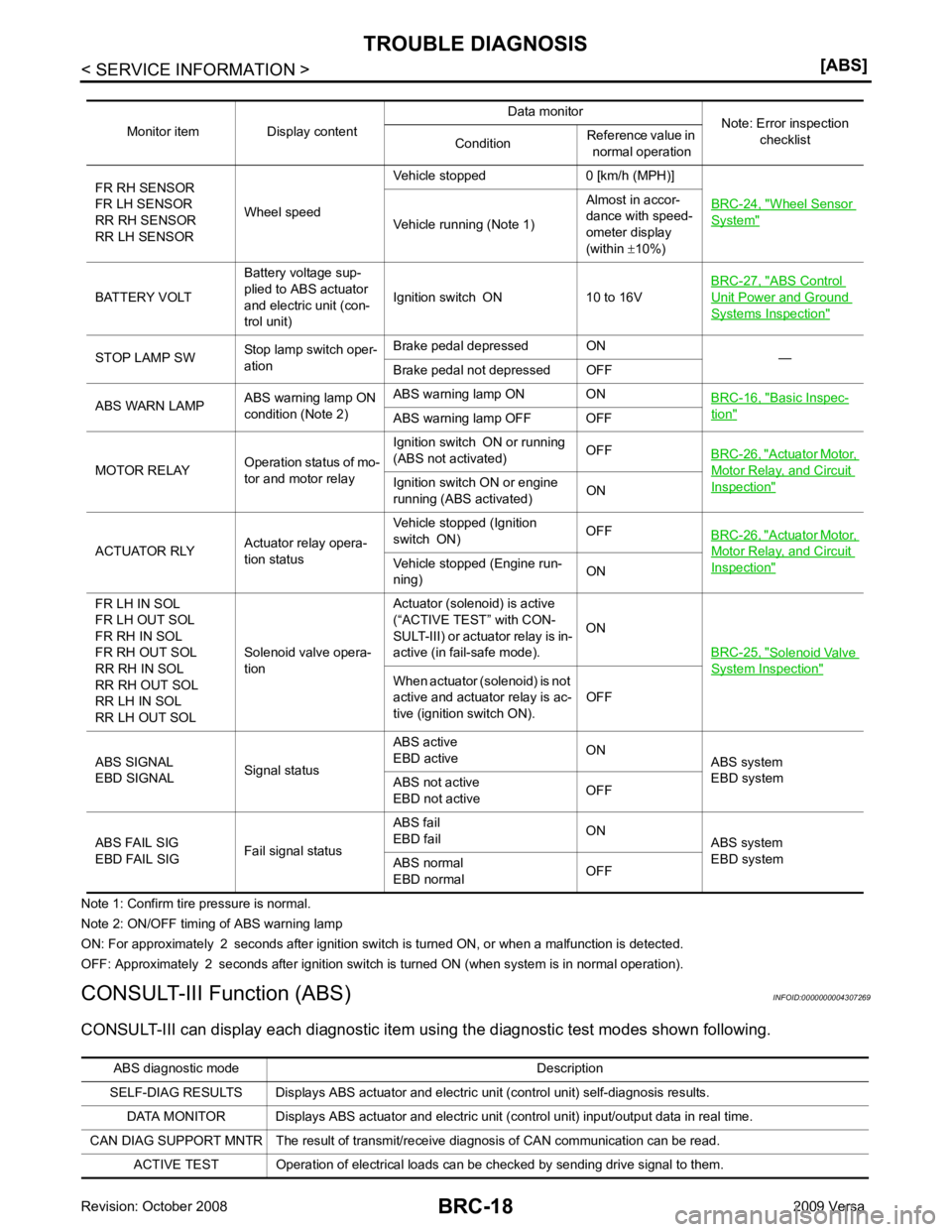
Vehicle running (Note 1)
Almost in accor-
dance with speed-
ometer display
(within ±10%)
BATTERY VOLT Battery voltage sup-
plied to ABS actuator
and electric unit (con-
trol unit) Ignition switch ON 10 to 16V
BRC-27, " ABS Control
Unit Power and Ground
Systems Inspection "
STOP LAMP SW
Stop lamp switch oper-
ation Brake pedal depressed ON
—
Brake pedal not depressed OFF
ABS WARN LAMP ABS warning lamp ON
condition (Note 2) ABS warning lamp ON ON
BRC-16, " Basic Inspec-
tion "
ABS warning lamp OFF OFF
MOTOR RELAY Operation status of mo-
tor and motor relay Ignition switch ON or running
(ABS not activated) OFF
BRC-26, " Actuator Motor,
Motor Relay, and Circuit
Inspection "Ignition switch ON or engine
running (ABS activated) ON
ACTUATOR RLY Actuator relay opera-
tion status Vehicle stopped (Ignition
switch ON) OFF
BRC-26, " Actuator Motor,
Motor Relay, and Circuit
Inspection "Vehicle stopped (Engine run-
ning) ON
FR LH IN SOL
FR LH OUT SOL
FR RH IN SOL
FR RH OUT SOL
RR RH IN SOL
RR RH OUT SOL
RR LH IN SOL
RR LH OUT SOL Solenoid valve opera-
tion Actuator (solenoid) is active
(“ACTIVE TEST” with CON-
SULT-III) or actuator relay is in-
active (in fail-safe mode). ON
BRC-25, " Solenoid Valve
System Inspection "
When actuator (solenoid) is not
active and actuator relay is ac-
tive (ignition switch ON). OFF
ABS SIGNAL
EBD SIGNAL Signal statusABS active
EBD active ON
ABS system
EBD system
ABS not active
EBD not active OFF
ABS FAIL SIG
EBD FAIL SIG Fail signal statusABS fail
EBD fail ON
ABS system
EBD system
ABS normal
EBD normal OFFABS diagnostic mo
de Description
SELF-DIAG RESULTS Displays ABS actuator and electric unit (control unit) self-diagnosis results.
DATA MONITOR Displays ABS actuator and electric unit (control unit) input/output data in real time.
CAN DIAG SUPPORT MNTR The result of transmit/receive diagnosis of CAN communication can be read. ACTIVE TEST Operation of electrical loads can be checked by sending drive signal to them.
Page 859 of 4331
BRC
N
O P
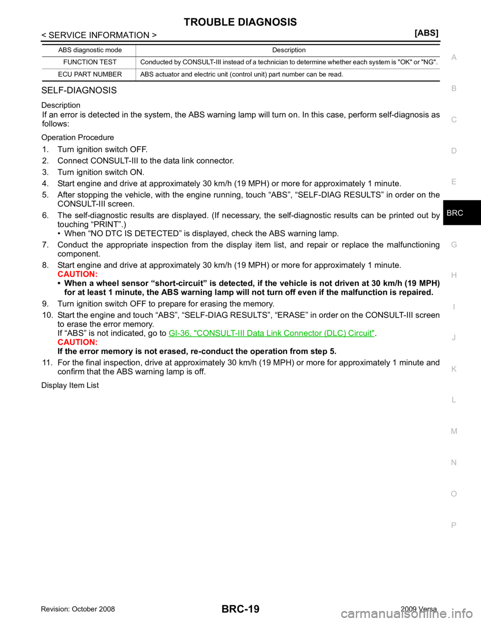
SELF-DIAGNOSIS
Description If an error is detected in the system, the ABS warning lamp will turn on. In this case, perform self-diagnosis as
follows:
Operation Procedure 1. Turn ignition switch OFF.
2. Connect CONSULT-III to the data link connector.
3. Turn ignition switch ON.
4. Start engine and drive at approximately 30 km/h (19 MPH) or more for approximately 1 minute.
5. After stopping the vehicle, with the engine running, t ouch “ABS”, “SELF-DIAG RESULTS” in order on the
CONSULT-III screen.
6. The self-diagnostic results are displayed. (If nece ssary, the self-diagnostic results can be printed out by
touching “PRINT”.)
• When “NO DTC IS DETECTED” is displayed, check the ABS warning lamp.
7. Conduct the appropriate inspection from the display item list, and repair or replace the malfunctioning
component.
8. Start engine and drive at approximately 30 km/h (19 MPH) or more for approximately 1 minute.
CAUTION:
• When a wheel sensor “short-circuit” is detected, if the vehicle is not driven at 30 km/h (19 MPH)
for at least 1 minute, the ABS warn ing lamp will not turn off even if the malfunction is repaired.
9. Turn ignition switch OFF to prepare for erasing the memory.
10. Start the engine and touch “ABS”, “SELF-DIAG RESU LTS”, “ERASE” in order on the CONSULT-III screen
to erase the error memory.
If “ABS” is not indicated, go to GI-36, " CONSULT-III Data Link Connector (DLC) Circuit " .
CAUTION:
If the error memory is not erased, re -conduct the operation from step 5.
11. For the final inspection, drive at approximately 30 km/h (19 MPH) or more for approximately 1 minute and
confirm that the ABS warning lamp is off.
Display Item List FUNCTION TEST Conducted by CONSULT-III in
stead of a technician to determine whether each sy stem is "OK" or "NG".
ECU PART NUMBER ABS actuator and electric unit (control unit) part number can be read.
ABS diagnostic mode Description
Page 860 of 4331
![NISSAN LATIO 2009 Service Manual Online Wheel Sensor
System " (Note 1)
RR LH SENSOR-1
[C1102] Circuit of rear LH wheel sensor is open.
FR RH SENSOR-1
[C1103] Circuit of front RH wheel sensor is open.
FR LH SENSOR-1
[C1104] Circuit of fron NISSAN LATIO 2009 Service Manual Online Wheel Sensor
System " (Note 1)
RR LH SENSOR-1
[C1102] Circuit of rear LH wheel sensor is open.
FR RH SENSOR-1
[C1103] Circuit of front RH wheel sensor is open.
FR LH SENSOR-1
[C1104] Circuit of fron](/img/5/57359/w960_57359-859.png)
Wheel Sensor
System " (Note 1)
RR LH SENSOR-1
[C1102] Circuit of rear LH wheel sensor is open.
FR RH SENSOR-1
[C1103] Circuit of front RH wheel sensor is open.
FR LH SENSOR-1
[C1104] Circuit of front LH wheel sensor is open.
RR RH SENSOR-2
[C1105] When the circuit in the rear RH wheel sensor is short-circuited or
when the sensor power voltage is outside the standard. When the
distance between the wheel sensor and sensor rotor is too large
and the sensor pulse cannot be recognized by the control unit.
RR LH SENSOR-2
[C1106] When the circuit in the rear LH wheel sensor is short-circuited or
when the sensor power voltage is outside the standard. When the
distance between the wheel sensor and sensor rotor is too large
and the sensor pulse cannot be recognized by the control unit.
FR RH SENSOR-2
[C1107] When the circuit in the front RH wheel sensor is short-circuited or
when the sensor power voltage is outside the standard. When the
distance between the wheel sensor and sensor rotor is too large
and the sensor pulse cannot be recognized by the control unit.
FR LH SENSOR-2
[C1108] When the circuit in the front LH wheel sensor is short-circuited or
when the sensor power voltage is outside the standard. When the
distance between the wheel sensor and sensor rotor is too large
and the sensor pulse cannot be recognized by the control unit.
ABS SENSOR
[ABNORMAL SIGNAL]
[C1115] Wheel sensor input is abnormal.
BATTERY VOLTAGE
[ABNORMAL]
[C1109] ABS actuator and electric unit (control unit) power voltage is too
low. BRC-27, " ABS Control
Unit Power and Ground
Systems Inspection "
CONTROLLER FAILURE
[C1110] Internal malfunction of ABS actuator
and electric unit (control unit)BRC-25, " ABS Control
Unit Inspection "
PUMP MOTOR
[C1111] During actuator motor operation with ON, when actuator motor
turns OFF or when control line for actuator motor relay is open. BRC-26, " Actuator Mo-
tor, Motor Relay, and Cir-
cuit Inspection "During actuator motor operation with OFF, when actuator motor
turns ON or when control line for relay is shorted to ground.
FR LH IN ABS SOL
[C1120] Circuit of front LH IN ABS solenoid
is open or shorted, or control
line is open or shorted to power supply or ground.
BRC-25, " Solenoid Valve
System Inspection "FR LH OUT ABS SOL
[C1121] Circuit of front LH OUT ABS solenoid is open or shorted, or control
line is open or shorted to power supply or ground.
FR RH IN ABS SOL
[C1122] Circuit of front RH IN ABS solenoid is open or shorted, or control
line is open or shorted to power supply or ground.
FR RH OUT ABS SOL
[C1123] Circuit of front RH OUT ABS solenoid is open or shorted, or con-
trol line is open or shorted to power supply or ground.
RR LH IN ABS SOL
[C1124] Circuit of rear LH IN ABS solenoid
is open or shorted, or control
line is open or shorted to power supply or ground.
RR LH OUT ABS SOL
[C1125] Circuit of rear LH OUT ABS solenoid
is open or shorted, or control
line is open or shorted to power supply or ground.
RR RH IN ABS SOL
[C1126] Circuit of rear RH IN ABS solenoid
is open or shorted, or control
line is open or shorted to power supply or ground.
RR RH OUT ABS SOL
[C1127] Circuit of rear RH OUT ABS solenoid is open or shorted, or control
line is open or shorted to power supply or ground.
Page 861 of 4331
BRC
N
O P
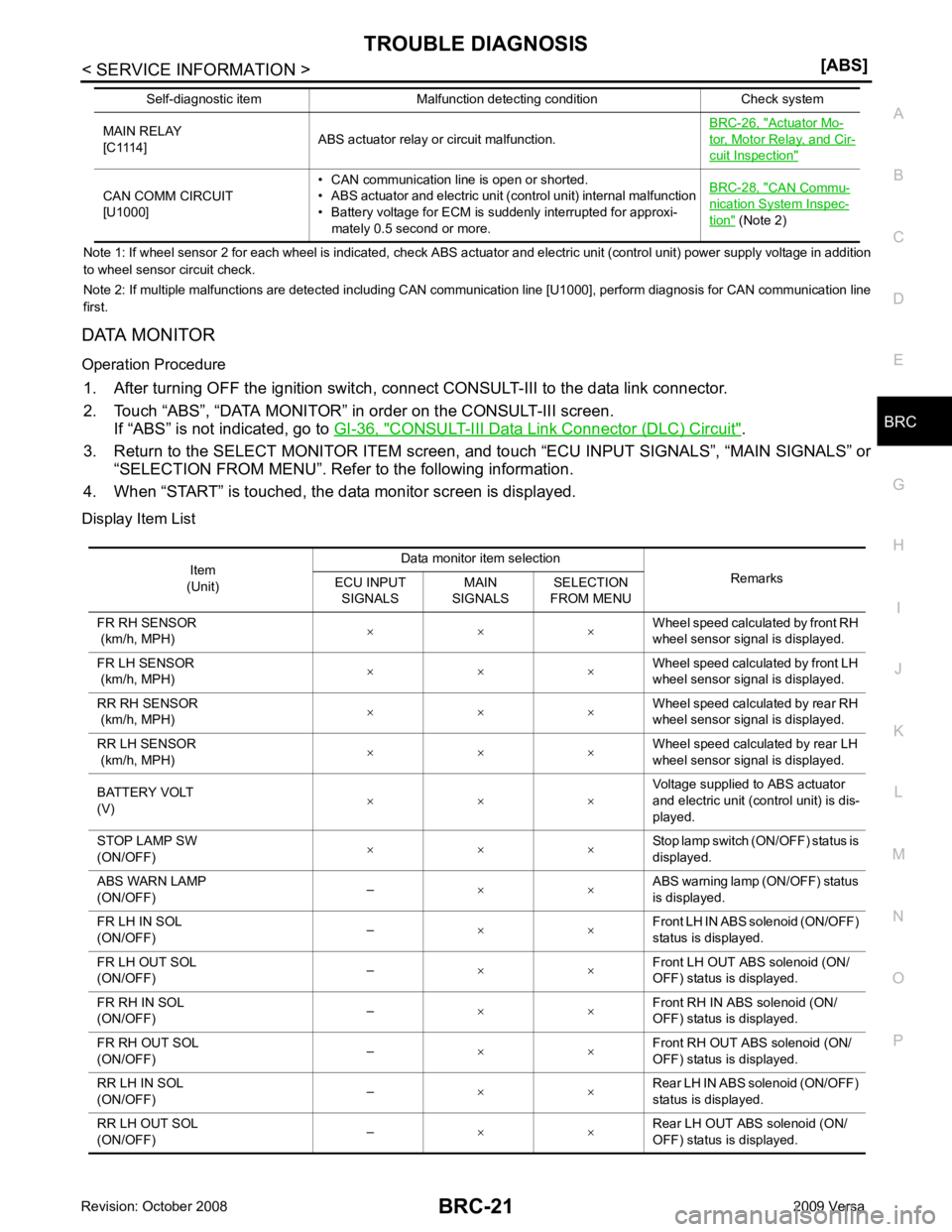
Note 1: If wheel sens
or 2 for each wheel is indicated, check ABS actuator and electric unit (control unit) power supply voltage in addition
to wheel sensor circuit check.
Note 2: If multiple malfunctions are detected including CAN communication line [U1000], perform diagnosis for CAN communication line
first.
DATA MONITOR
Operation Procedure 1. After turning OFF the ignition switch, c onnect CONSULT-III to the data link connector.
2. Touch “ABS”, “DATA MONITOR” in order on the CONSULT-III screen. If “ABS” is not indicated, go to GI-36, " CONSULT-III Data Link Connector (DLC) Circuit " .
3. Return to the SELECT MONITOR ITEM screen, and touch “ECU INPUT SIGNALS”, “MAIN SIGNALS” or
“SELECTION FROM MENU”. Refer to the following information.
4. When “START” is touched, the data monitor screen is displayed.
Display Item List MAIN RELAY
[C1114] ABS actuator relay or circuit malfunction. BRC-26, " Actuator Mo-
tor, Motor Relay, and Cir-
cuit Inspection "
CAN COMM CIRCUIT
[U1000] • CAN communication line is open or shorted.
• ABS actuator and electric unit (control unit) internal malfunction
• Battery voltage for ECM is suddenly interrupted for approxi-
mately 0.5 second or more. BRC-28, " CAN Commu-
nication System Inspec-
tion " (Note 2)
Self-diagnostic item Malfunction detecting condition Check system Item
(Unit) Data monitor item selection
Remarks
ECU INPUT
SIGNALS MAIN
SIGNALS SELECTION
FROM MENU
FR RH SENSOR
(km/h, MPH) × × × Wheel speed calculated by front RH
wheel sensor signal is displayed.
FR LH SENSOR
(km/h, MPH) × × ×
Wheel speed calculated by front LH
wheel sensor signal is displayed.
RR RH SENSOR
(km/h, MPH) × × × Wheel speed calculated by rear RH
wheel sensor signal is displayed.
RR LH SENSOR
(km/h, MPH) × × × Wheel speed calculated by rear LH
wheel sensor signal is displayed.
BATTERY VOLT
(V) × × × Voltage supplied to ABS actuator
and electric unit (control unit) is dis-
played.
STOP LAMP SW
(ON/OFF) × × × Stop lamp switch (ON/OFF) status is
displayed.
ABS WARN LAMP
(ON/OFF) –
× × ABS warning lamp (ON/OFF) status
is displayed.
FR LH IN SOL
(ON/OFF) –
× × Front LH IN ABS solenoid (ON/OFF)
status is displayed.
FR LH OUT SOL
(ON/OFF) –
× × Front LH OUT ABS solenoid (ON/
OFF) status is displayed.
FR RH IN SOL
(ON/OFF) –
× × Front RH IN ABS solenoid (ON/
OFF) status is displayed.
FR RH OUT SOL
(ON/OFF) –
× × Front RH OUT ABS solenoid (ON/
OFF) status is displayed.
RR LH IN SOL
(ON/OFF) –
× × Rear LH IN ABS solenoid (ON/OFF)
status is displayed.
RR LH OUT SOL
(ON/OFF) –
× × Rear LH OUT ABS solenoid (ON/
OFF) status is displayed.
Page 864 of 4331
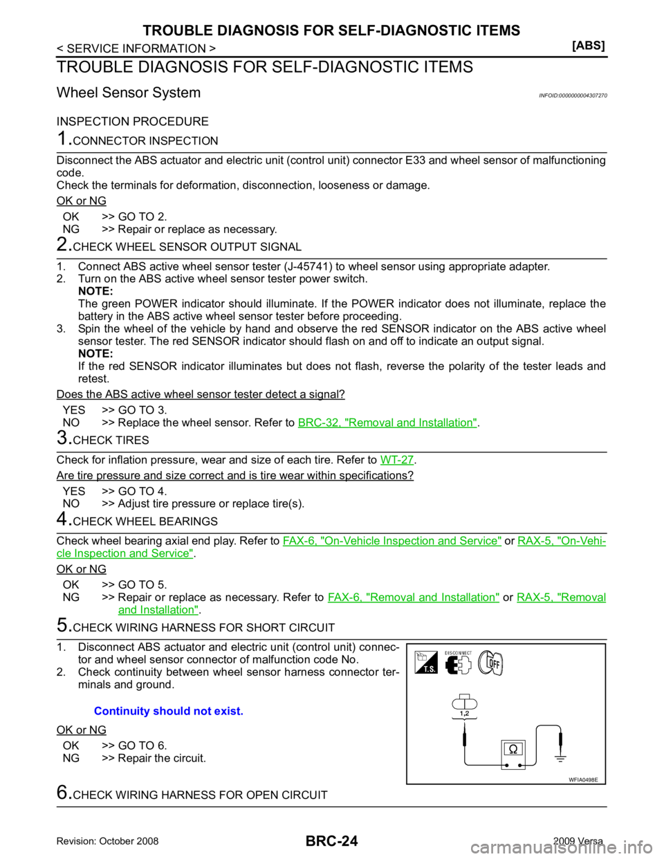
OK >> GO TO 2.
NG >> Repair or replace as necessary. YES >> GO TO 3.
NO >> Replace the wheel sensor. Refer to BRC-32, " Removal and Installation " .
.
Are tire pressure and size correct and is tire wear within specifications? YES >> GO TO 4.
NO >> Adjust tire pressure or replace tire(s). On-Vehicle Inspection and Service " or
RAX-5, " On-Vehi-
cle Inspection and Service " .
OK or NG OK >> GO TO 5.
NG >> Repair or replace as necessary. Refer to FAX-6, " Removal and Installation " or
RAX-5, " Removal
and Installation " .
OK >> GO TO 6.
NG >> Repair the circuit.
Page 865 of 4331
BRC
N
O P
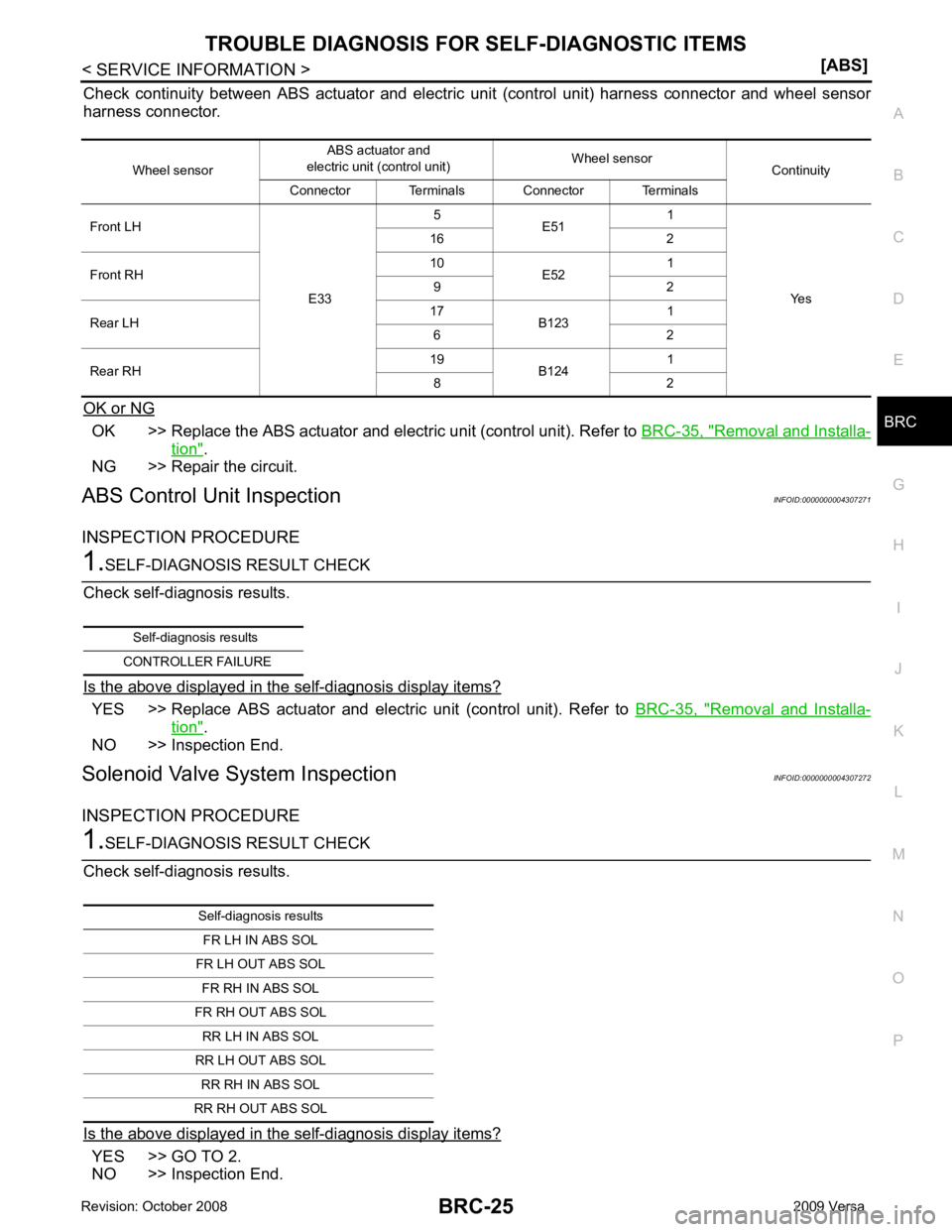
Check continuity between ABS actuator and electric
unit (control unit) harness connector and wheel sensor
harness connector.
OK or NG OK >> Replace the ABS actuator and electric unit (control unit). Refer to
BRC-35, " Removal and Installa-
tion " .
NG >> Repair the circuit.
ABS Control Unit Inspection INFOID:0000000004307271
INSPECTION PROCEDURE YES >> Replace ABS actuator and electr
ic unit (control unit). Refer to BRC-35, " Removal and Installa-
tion " .
NO >> Inspection End.
Solenoid Valve System Inspection INFOID:0000000004307272
INSPECTION PROCEDURE YES >> GO TO 2.
NO >> Inspection End. Wheel sensor
ABS actuator and
electric unit (control unit) Wheel sensor
Continuity
Connector Terminals Connector Terminals
Front LH
E335
E51 1
Yes
16 2
Front RH 10
E52 1
9 2
Rear LH 17
B123 1
6 2
Rear RH 19
B124 1
8 2 Self-diagnosis results
CONTROLLER FAILURE Self-diagnosis results
FR LH IN ABS SOL
FR LH OUT ABS SOL FR RH IN ABS SOL
FR RH OUT ABS SOL RR LH IN ABS SOL
RR LH OUT ABS SOL RR RH IN ABS SOL
RR RH OUT ABS SOL