sensor NISSAN LATIO 2009 Service Manual PDF
[x] Cancel search | Manufacturer: NISSAN, Model Year: 2009, Model line: LATIO, Model: NISSAN LATIO 2009Pages: 4331, PDF Size: 58.04 MB
Page 262 of 4331
AT
N
O P
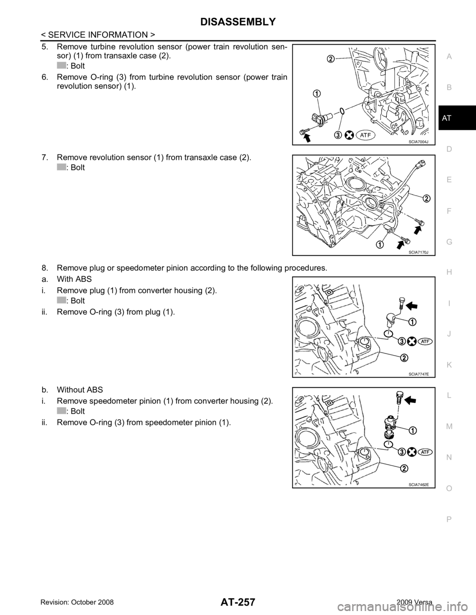
5. Remove turbine revolution sensor (power train revolution sen-
sor) (1) from transaxle case (2).
: Bolt
6. Remove O-ring (3) from turbine revolution sensor (power train revolution sensor) (1).
7. Remove revolution sensor (1) from transaxle case (2). : Bolt
8. Remove plug or speedometer pinion according to the following procedures.
a. With ABS
i. Remove plug (1) from converter housing (2). : Bolt
ii. Remove O-ring (3) from plug (1).
b. Without ABS
i. Remove speedometer pinion (1) from converter housing (2). : Bolt
ii. Remove O-ring (3) from speedometer pinion (1). SCIA7747E
SCIA7462E
Page 290 of 4331
AT
N
O P
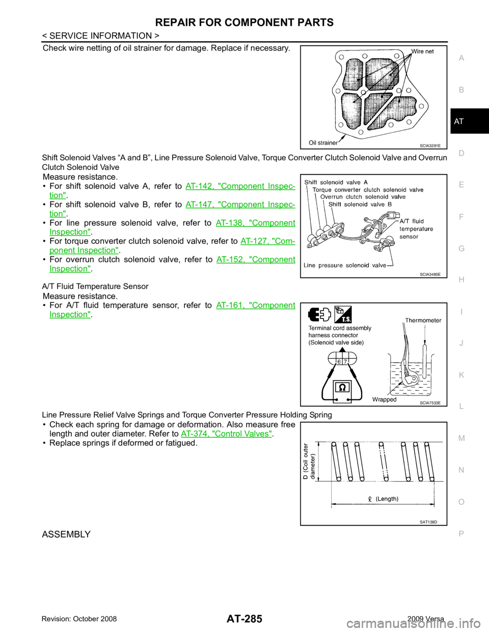
Check wire netting of oil strainer for damage. Replace if necessary.
Shift Solenoid Valves “A and B”, Line Pressure Solenoid Valve, Torque Conv erter Clutch Solenoid Valve and Overrun
Clutch Solenoid Valve
Measure resistance.
• For shift solenoid valve A, refer to AT-142, " Component Inspec-
tion " .
• For shift solenoid valve B, refer to AT-147, " Component Inspec-
tion " .
• For line pressure solenoid valve, refer to AT-138, " Component
Inspection " .
• For torque converter clutch solenoid valve, refer to AT-127, " Com-
ponent Inspection " .
• For overrun clutch solenoid valve, refer to AT-152, " Component
Inspection " .
A/T Fluid Temperature Sensor Measure resistance.
• For A/T fluid temperature sensor, refer to AT-161, " Component
Inspection " .
Line Pressure Relief Valve Springs and To rque Converter Pressure Holding Spring
• Check each spring for damage or deformation. Also measure free length and outer diameter. Refer to AT-374, " Control Valves " .
• Replace springs if deformed or fatigued.
ASSEMBLY SCIA3485E
SAT138D
Page 375 of 4331
AT-370< SERVICE INFORMATION >
ASSEMBLY
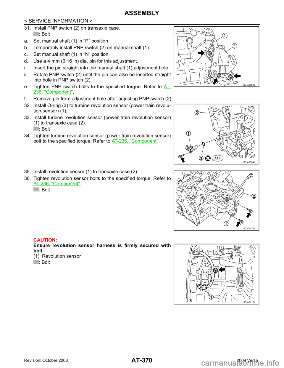
31. Install PNP switch (2) on transaxle case. : Bolt
a. Set manual shaft (1) in “P” position.
b. Temporarily install PNP switch (2) on manual shaft (1).
c. Set manual shaft (1) in “N” position.
d. Use a 4 mm (0.16 in) dia. pin for this adjustment.
i. Insert the pin straight into the manual shaft (1) adjustment hole.
ii. Rotate PNP switch (2) until the pin can also be inserted straight into hole in PNP switch (2).
e. Tighten PNP switch bolts to the specified torque. Refer to AT-236, " Component " .
f. Remove pin from adjustment hole after adjusting PNP switch (2).
32. Install O-ring (3) to turbine revolution sensor (power train revolu- tion sensor) (1).
33. Install turbine revolution sensor (power train revolution sensor) (1) to transaxle case (2).
: Bolt
34. Tighten turbine revolution sensor (power train revolution sensor) bolt to the specified torque. Refer to AT-236, " Component " .
35. Install revolution sensor (1) to transaxle case (2).
36. Tighten revolution sensor bolts to the specified torque. Refer to AT-236, " Component " .
: Bolt
CAUTION:
Ensure revolution sensor harness is firmly secured with
bolt.
(1): Revolution sensor
: Bolt SCIA5904J
SCIA7004J
SCIA7170J
SCIA6518J
Page 384 of 4331

AT
N
O P
Solenoid Valves
INFOID:0000000004305554
A/T Fluid Temperature Sensor INFOID:0000000004305555
Remarks: Specification data are reference values.
Revolution Sensor INFOID:0000000004305556
Dropping Resistor INFOID:0000000004305557
Turbine Revolution Sensor (Power Train Revolution Sensor) INFOID:0000000004305558
Solenoid valve designation Resistance (Approx.) Terminal
Shift solenoid valve A 20 - 30 Ω2
Shift solenoid valve B 5 - 20 Ω1
Overrun clutch solenoid valve 20 - 30 Ω3
Line pressure solenoid valve 2.5 - 5.0 Ω4
Torque converter clutch solenoid valve 5 - 20 Ω5Condition Specification (Approx.)
Cold [20 °C (68 °F)]
↓
Hot [80 °C (176 °F)] 1.5V
↓
0.5V 2.5 k
Ω
↓
0.3 k Ω Resistance
12Ω (Approx.) Condition Judgment standard
When driving at 20 km/h (12 MPH) 360 Hz (Approx.)
Page 477 of 4331
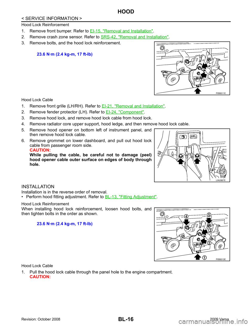
Removal and Installation " .
2. Remove crash zone sensor. Refer to SRS-42, " Removal and Installation " .
3. Remove bolts, and the hood lock reinforcement.
Hood Lock Cable
1. Remove front grille (LH/RH). Refer to EI-21, " Removal and Installation " .
2. Remove fender protector (LH). Refer to EI-24, " Component " .
3. Remove hood lock, and remove hood lock cable from hood lock.
4. Remove radiator core upper support, hood ledge, and then remove hood lock cable.
5. Remove hood opener on bottom left of instrument panel, and then remove hood lock cable.
6. Remove grommet on lower dashboard, and pull out hood lock cable from passenger room side.
CAUTION:
While pulling the cable, be car eful not to damage (peel)
hood opener cable outer surface on edges of body through
hole.
INSTALLATION
Installation is in the reverse order of removal.
• Perform hood fitting adjustment. Refer to BL-13, " Fitting Adjustment " .
Hood Lock Reinforcement
When installing hood lock reinforcement, loosen hood bolts, and
then tighten bolts in the order as shown.
Hood Lock Cable
1. Pull the hood lock cable through the panel hole to the engine compartment. CAUTION: 23.6 N·m (2.4 kg-m, 17 ft-lb)
LIIA2667E
Page 551 of 4331

Key reminder functionsIntelligent Key
Door switch
Unlock sensor
Door lock actuator
Inside key antenna
Intelligent Key warning buzzer(s)
Intelligent Key unit
CAN communication system
BCM
Any door open to close × × × × × × × × ×
Page 570 of 4331
BL
N
O P
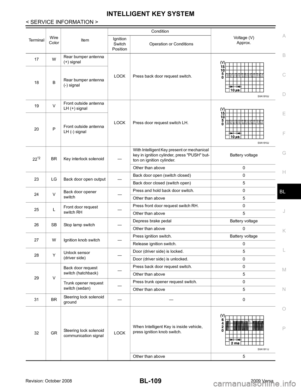
17 W
Rear bumper antenna
(+) signal
LOCK Press back door request switch.
18 B Rear bumper antenna
(-) signal
19 V Front outside antenna
LH (+) signal
LOCK Press door request switch LH.
20 P Front outside antenna
LH (-) signal
22 *2
BR Key interlock solenoid — With Intelligent Key present or mechanical
key in ignition cylinder, press "PUSH" but-
ton on ignition cylinder. Battery voltage
Other than above 0
23 LG Back door open output — Back door open (switch closed) 0
Back door closed (switch open) 5
24 V Back door opener
switch —Press and hold back door switch. 0
Other than above 5
25 L Front door request
switch RH —Press front door request switch RH. 0
Other than above 5
26 SB Stop lamp switch — Depress brake pedal Battery voltage
Other than above 0
27 W Ignition knob switch — Press ignition switch. Battery voltage
Release ignition switch. 0
28 Y Unlock sensor
(driver side) —Door (driver si
de) is locked. 5
Door (driver side ) is unlocked. 0
29 V Back door request
switch (hatchback) —Press back door request switch. 0
Other than above 5
Trunk opener request
switch (sedan) —Press trunk opener request switch. 0
Other than above 5
31 BR Steering lock solenoid
ground — — 0
32 GR Steering lock solenoid
communication signal LOCKWhen Intelligent Key is inside vehicle,
press ignition knob switch.
Other than above 5
Terminal
Wire
Color Item Condition
Voltage (V)Approx.
Ignition
Switch
Position Operation or Conditions SIIA1911J
Page 583 of 4331
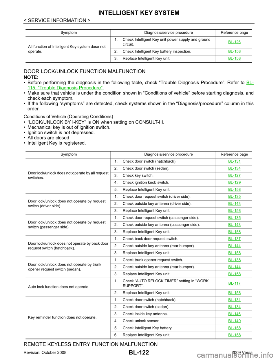
115, " Trouble Diagnosis Procedure " .
• Make sure that vehicle is under the condition shown in “Conditions of vehicle” before starting diagnosis, and
check each symptom.
• If the following “symptoms” are detected, check system s shown in the “Diagnosis/procedure” column in this
order.
Conditions of Vehicle (Operating Conditions)
• “LOCK/UNLOCK BY I-KEY” is ON when setting on CONSULT-III.
• Mechanical key is out of ignition switch.
• Ignition switch is not depressed.
• All doors are closed.
• Intelligent Key is registered.
REMOTE KEYLESS ENTRY FUNCTION MALFUNCTION
Symptom Diagnosis/service procedure Reference page
All function of Intelligent Key system dose not
operate. 1. Check Intelligent Key unit power supply and ground
circuit. BL-126 2. Check Intelligent Key battery inspection.
BL-158 3. Replace Intelligent Key unit.
BL-158Symptom Diagnosis/service procedure Reference page
Door lock/unlock does not operate by all request
switches. 1. Check door switch (hatchback).
BL-131 2. Check door switch (sedan).
BL-134 3. Check key switch.
BL-127 4. Check ignition knob switch.
BL-129 5. Replace Intelligent Key unit.
BL-158Door lock/unlock does not operate by request
switch (driver side). 1. Check door request switch (driver side).
BL-135 2. Check outside key antenna (driver side).
BL-143 3. Replace Intelligent Key unit.
BL-158Door lock/unlock does not operate by request
switch (passenger side). 1. Check door request switch (passenger side).
BL-135 2. Check outside key antenna (passenger side).
BL-143 3. Replace Intelligent Key unit.
BL-158Door lock/unlock does not operate by back door
request switch (hatchback). 1. Check back door request switch.
BL-137 2. Check outside key antenna (rear bumper).
BL-144 3. Replace Intelligent Key unit.
BL-158Door lock/unlock does not operate by trunk
opener request switch (sedan). 1. Check trunk opener request switch.
BL-138 2. Check outside key antenna (rear bumper).
BL-144 3. Replace Intelligent Key unit.
BL-158Auto lock function does not operate.
1. Check “AUTO RELOCK TI
MER” setting in “WORK
SUPPORT”. BL-117 2. Replace Intelligent Key unit.
BL-158Key reminder function does not operate.
1. Check door switch (hatchback).
BL-131 2. Check door switch (sedan).
BL-134 3. Check inside key antenna.
BL-146 4. Check unlock sensor.
BL-140 5. Check Intelligent Key battery.
BL-158 6. Replace Intelligent Key unit.
BL-158
Page 584 of 4331
BL
N
O P
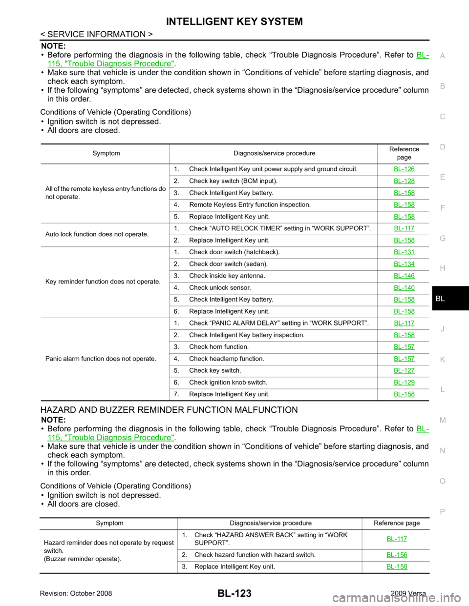
NOTE:
• Before performing the diagnosis in the following table, check “Trouble Diagnosis Procedure”. Refer to BL-115, " Trouble Diagnosis Procedure " .
• Make sure that vehicle is under the condition shown in “Conditions of vehicle” before starting diagnosis, and
check each symptom.
• If the following “symptoms” are detected, check syst ems shown in the “Diagnosis/service procedure” column
in this order.
Conditions of Vehicle (Operating Conditions) • Ignition switch is not depressed.
• All doors are closed.
HAZARD AND BUZZER REMINDER FUNCTION MALFUNCTION NOTE:
• Before performing the diagnosis in the following table, check “Trouble Diagnosis Procedure”. Refer to BL-115, " Trouble Diagnosis Procedure " .
• Make sure that vehicle is under the condition shown in “Conditions of vehicle” before starting diagnosis, and
check each symptom.
• If the following “symptoms” are detected, check syst ems shown in the “Diagnosis/service procedure” column
in this order.
Conditions of Vehicle (Operating Conditions) • Ignition switch is not depressed.
• All doors are closed. Symptom Diagnosis/service procedure
Reference
page
All of the remote keyless entry functions do
not operate. 1. Check Intelligent Key unit power supply and ground circuit.
BL-1262. Check key switch (BCM input).
BL-1283. Check Intelligent Key battery.
BL-1584. Remote Keyless Entry function inspection.
BL-1585. Replace Intelligent Key unit.
BL-158Auto lock function does not operate.
1. Check “AUTO RELOCK TIMER”
setting in “WORK SUPPORT”. BL-117 2. Replace Intelligent Key unit.
BL-158Key reminder function does not operate.
1. Check door switch (hatchback).
BL-1312. Check door switch (sedan).
BL-1343. Check inside key antenna.
BL-1464. Check unlock sensor.
BL-1405. Check Intelligent Key battery.
BL-1586. Replace Intelligent Key unit.
BL-158Panic alarm function does not operate.
1. Check “PANIC ALARM DELAY” setting in “WORK SUPPORT”.
BL-1172. Check Intelligent Key battery inspection.
BL-1583. Check horn function.
BL-1574. Check headlamp function.
BL-1575. Check key switch.
BL-1276. Check ignition knob switch.
BL-1297. Replace Intelligent Key unit.
BL-158Symptom Diagnosis/service procedure Reference page
Hazard reminder does not operate by request
switch.
(Buzzer reminder operate). 1. Check “HAZARD ANSWER BACK” setting in “WORK
SUPPORT”. BL-1172. Check hazard function with hazard switch.
BL-1563. Replace Intelligent Key unit.
BL-158
Page 601 of 4331
BL-140< SERVICE INFORMATION >
INTELLIGENT KEY SYSTEM4.
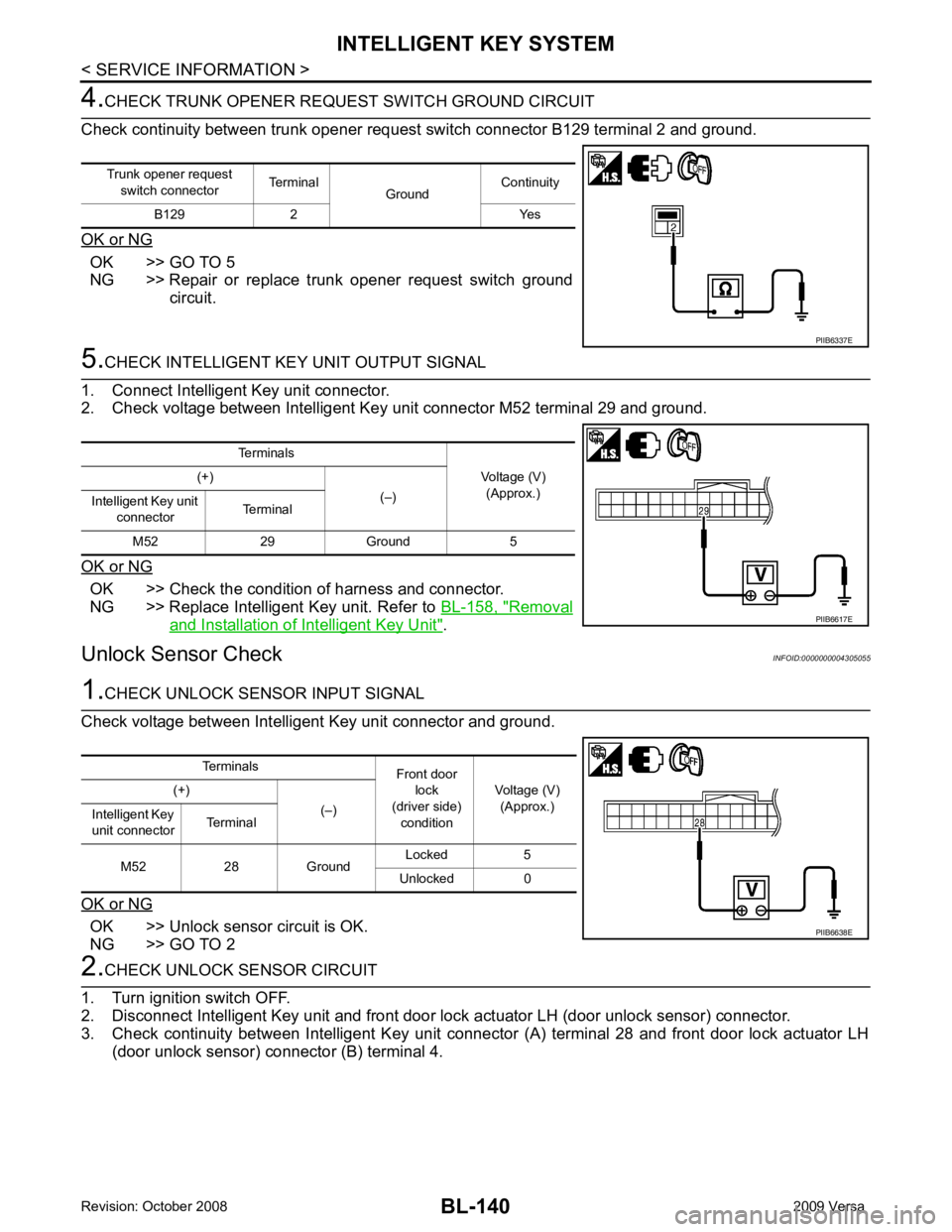
CHECK TRUNK OPENER REQU EST SWITCH GROUND CIRCUIT
Check continuity between trunk opener request switch connector B129 terminal 2 and ground.
OK or NG OK >> GO TO 5
NG >> Repair or replace trunk opener request switch ground
circuit. 5.
CHECK INTELLIGENT KEY UNIT OUTPUT SIGNAL
1. Connect Intelligent Key unit connector.
2. Check voltage between Intelligent Key unit connector M52 terminal 29 and ground.
OK or NG OK >> Check the condition of harness and connector.
NG >> Replace Intelligent Key unit. Refer to BL-158, " Removal
and Installation of Intelligent Key Unit " .
Unlock Sensor Check INFOID:00000000043050551.
CHECK UNLOCK SENSOR INPUT SIGNAL
Check voltage between Intelligent Key unit connector and ground.
OK or NG OK >> Unlock sensor circuit is OK.
NG >> GO TO 2 2.
CHECK UNLOCK SENSOR CIRCUIT
1. Turn ignition switch OFF.
2. Disconnect Intelligent Key unit and front door lock actuator LH (door unlock sensor) connector.
3. Check continuity between Intelligent Key unit connec tor (A) terminal 28 and front door lock actuator LH
(door unlock sensor) connector (B) terminal 4.
Trunk opener request
switch connector Terminal
GroundContinuity
B129 2 Yes PIIB6337E
Terminals
Voltage (V)(Approx.)
(+)
(–)
Intelligent Key unit
connector Terminal
M52 29 Ground 5 PIIB6617E
Terminals
Front door
lock
(driver side) condition Voltage (V)
(Approx.)
(+)
(–)
Intelligent Key
unit connector Terminal
M52 28 Ground Locked 5
Unlocked 0 PIIB6638E