NISSAN LATIO 2009 Service Repair Manual
Manufacturer: NISSAN, Model Year: 2009, Model line: LATIO, Model: NISSAN LATIO 2009Pages: 4331, PDF Size: 58.04 MB
Page 941 of 4331
CO
NP
O
WATER OUTLET AND WATER CONTROL VALVE
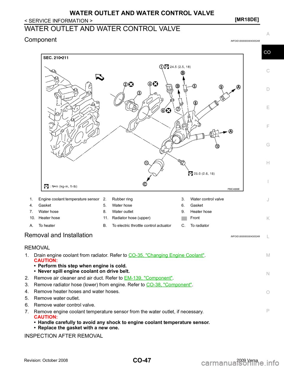
Component INFOID:0000000004305248
Removal and Installation INFOID:0000000004305249
REMOVAL 1. Drain engine coolant from radiator. Refer to CO-35, " Changing Engine Coolant " .
CAUTION:
• Perform this step when engine is cold.
• Never spill engine coolant on drive belt.
2. Remove air cleaner and air duct. Refer to EM-139, " Component " .
3. Remove radiator hose (lower) from engine. Refer to CO-38, " Component " .
4. Remove heater hoses and water hoses.
5. Remove water outlet.
6. Remove water control valve.
7. Remove engine coolant temperature sensor from the water outlet, if necessary. CAUTION:
• Handle carefully to avoid any shock to engine coolant temperature sensor.
• Replace the gasket with a new one.
INSPECTION AFTER REMOVAL 1. Engine coolant temperature sensor 2. Rubber ring 3. Water control valve
4. Gasket 5. Water hose 6. Gasket
7. Water hose 8. Water outlet 9. Heater hose
10. Heater hose 11. Radiator hose (upper) Front
A. To heater B. To electric throttle control actuator C. To radiator
Page 942 of 4331
![NISSAN LATIO 2009 Service Repair Manual CO-48< SERVICE INFORMATION >
[MR18DE]
WATER OUTLET AND WATER CONTROL VALVE
• Place a thread (A) so that it is c aught in the valves of water control
valve (1). Immerse fully in a container (B NISSAN LATIO 2009 Service Repair Manual CO-48< SERVICE INFORMATION >
[MR18DE]
WATER OUTLET AND WATER CONTROL VALVE
• Place a thread (A) so that it is c aught in the valves of water control
valve (1). Immerse fully in a container (B](/img/5/57359/w960_57359-941.png)
CO-48< SERVICE INFORMATION >
[MR18DE]
WATER OUTLET AND WATER CONTROL VALVE
• Place a thread (A) so that it is c aught in the valves of water control
valve (1). Immerse fully in a container (B) filled with water. Heat
while stirring.
• The valve opening temperature is the temperature at which the
valve opens and falls from the thread.
• Continue heating. Check the full-open valve lift amount.
NOTE:
The full-open valve lift amount standard temperature for water con-
trol valve is the reference value.
• After checking the full-open valve lift amount, lower the water tem- perature and check the valve closing temperature.
• If out of the specification, replace water control valve.
INSTALLATION
Installation is in the reverse order of removal.
• Use the following procedure to install the water control valve.
- Install water control valve while making rubber ring (1) groove fit to water control valve flange (A) around the whole circumference.
CAUTION:
Replace the rubber ring with a new one.
- While the mark (A) points to up, install water control valve (2) with frame center (B) facing straight upward into water outlet (1).
• Use the following procedure to install the water outlet.
- Install the water outlet to the cylinder head without disp lacing the water control valve from the valve position.
• Use the following procedure to install the water hoses. Valve opening temperature 93.5 - 96.5
°C (200 - 206 °F)
Full-open valve lift amount 8 mm/ 108 °C (0.315 in/ 226 °F)
Valve closing temperature 90 °C (194 °F) PBIC3314J
PBIC3317J
PBIC4700E
Page 943 of 4331
CO
NP
O
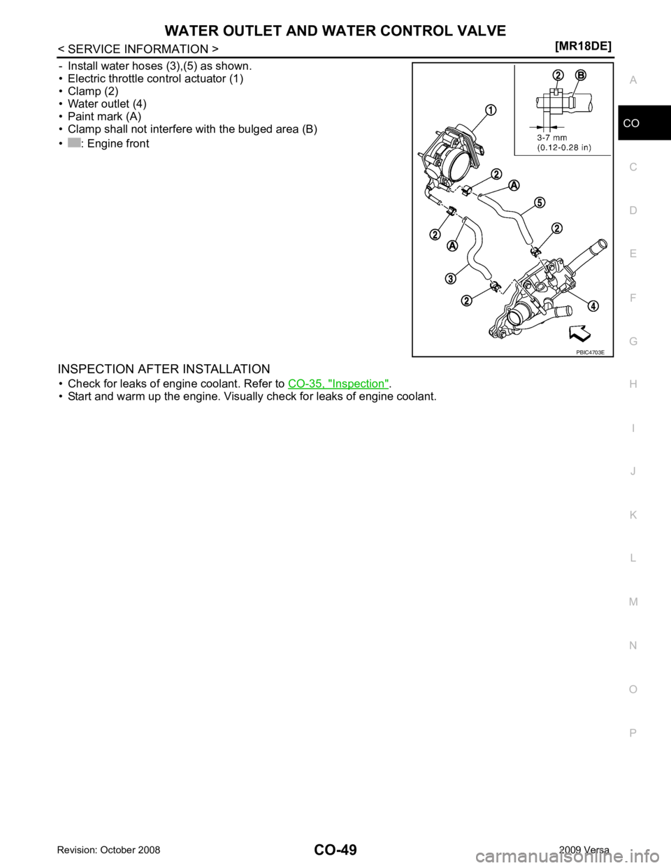
- Install water hoses (3),(5) as shown.
• Electric throttle control actuator (1)
• Clamp (2)
• Water outlet (4)
• Paint mark (A)
• Clamp shall not interfere with the bulged area (B)
• : Engine front
INSPECTION AFTER INSTALLATION • Check for leaks of engine coolant. Refer to CO-35, " Inspection " .
• Start and warm up the engine. Visually check for leaks of engine coolant.
Page 944 of 4331

Valve opening temperature 80.5 - 83.5
°C (177 - 182 °F)
Full-open valve lift amount 8 mm/ 95 °C (0.315 in/ 203 °F)
Valve closing temperature 77 °C (171 °F) Valve opening temperature 93.5 - 96.5
°C (200 - 206 °F)
Full-open valve lift amount 8 mm/ 108 °C (0.315 in/ 226 °F)
Valve closing temperature 90°C (194 °F) Cap relief pressure
Standard 78 - 98 (0.78 - 0.98, 0.8 - 1.0, 11- 14)
Limit 59 (0.59, 0.6, 9)
Leakage test pressure 157 (1.57, 1.6, 23)
Page 945 of 4331
CVT
N
O P
CONTENTS
CVT
RE0F08A
SERVICE INFORMATION .. ..........................
9
INDEX FOR DTC ............................................ .....9
Alphabetical Index ............................................... ......9
DTC No. Index .................................................... ......9
PRECAUTIONS .............................................. ....11
Precaution for Supplemental Restraint System
(SRS) "AIR BAG" and "SEAT BELT PRE-TEN-
SIONER" ............................................................. ....
11
Precaution Necessary fo r Steering Wheel Rota-
tion After Battery Disconnect ............................... ....
11
Precaution for On Board Diagnosis (OBD) System
of CVT and Engine .............................................. ....
12
Service After Replacing TCM and Transaxle As-
sembly ................................................................. ....
12
Removal and Installation Procedure for CVT Unit
Connector ............................................................ ....
13
Precaution ........................................................... ....14
Service Notice or Precaution ............................... ....15
PREPARATION .............................................. ....16
Special Service Tool ........................................... ....16
Commercial Service Tool .................................... ....16
CVT FLUID ..................................................... ....17
Checking CVT Fluid ............................................ ....17
Changing CVT Fluid ............................................ ....18
CVT Fluid Cooler Cleanin g .....................................18
CVT SYSTEM ... .............................................. ....22
Cross-Sectional View - RE0F08A ....................... ....22
Control System .................................................... ....23
Hydraulic Control System ........................................24
TCM Function ...................................................... ....24
CAN Communication ........................................... ....25
Input/Output Signal of TCM ................................. ....26
Line Pressure and Secondary Pressure Control . ....26
Shift Control ........................................................ ....27
Lock-up and Select Control ................................. ....28 Control Valve .......................................................
....29
ON BOARD DIAGNOSTIC (OBD) SYSTEM .... 30
Introduction .......................................................... ....30
OBD-II Function for CVT System ........................ ....30
One or Two Trip Detection Logic of OBD-II ......... ....30
OBD-II Diagnostic Trouble Code (DTC) .............. ....30
Malfunction Indicator Lamp (MIL) ............................31
TROUBLE DIAGNOSIS .................................... 33
DTC Inspection Priority Chart .............................. ....33
Fail-Safe .............................................................. ....33
How to Perform Trouble Diagnosis for Quick and
Accurate Repair ................................................... ....
34
CVT Electrical Parts Location .............................. ....39
Circuit Diagram .................................................... ....40
Inspections before Trouble Diagnosis ................. ....40
Road Test ............................................................ ....44
Check before Engine Is Started ........................... ....45
Check at Idle ........................................................ ....45
Cruise Test .......................................................... ....47
Vehicle Speed When Shifting Gears ................... ....49
TCM Terminal and Refere nce Value .......................49
CONSULT-III Function (TRANSMISSION) .......... ....51
Diagnosis Procedure withou t CONSULT-III ............59
DTC U1000 CAN COMMUNICATION LINE ..... 60
Description ........................................................... ....60
On Board Diagnosis Logic ................................... ....60
Possible Cause .................................................... ....60
DTC Confirmation Procedure .............................. ....60
Wiring Diagram - CVT - CAN ............................... ....61
Diagnosis Procedure ........................................... ....62
DTC U1010 TRANSMISSION CONTROL
MODULE (CAN) ................................................ 63
Description ........................................................... ....63
On Board Diagnosis Logic ................................... ....63
Possible Cause .................................................... ....63
DTC Confirmation Procedure .............................. ....63
Diagnosis Procedure ........................................... ....63
Page 946 of 4331

Page 947 of 4331
CVT
N
O
P
N
Description ..........................................................
..
104
CONSULT-III Refe rence Value in Data Monitor
Mode ................................................................... ..
104
On Board Diagnosis Logic .................................. ..104
Possible Cause ................................................... ..104
DTC Confirmation Procedure .............................. ..104
Diagnosis Procedure ........................................... ..104
DTC P0776 PRESSURE CONTROL SOLE-
NOID B PERFORMANCE (SEC PRESSURE
SOLENOID VALVE) ....................................... ..106
Description .......................................................... ..106
CONSULT-III Refe rence Value in Data Monitor
Mode ................................................................... ..
106
On Board Diagnosis Logic .................................. ..106
Possible Cause ................................................... ..106
DTC Confirmation Procedure .............................. ..106
Diagnosis Procedure ........................................... ..106
DTC P0778 PRESSURE CONTROL SOLE-
NOID B ELECTRICAL (SEC PRESSURE SO-
LENOID VALVE) ............................................ ..
108
Description .......................................................... ..108
CONSULT-III Refe rence Value in Data Monitor
Mode ................................................................... ..
108
On Board Diagnosis Logic .................................. ..108
Possible Cause ................................................... ..108
DTC Confirmation Procedure .............................. ..108
Wiring Diagram - CVT - SECPSV .........................109
Diagnosis Procedure ........................................... ..110
Component Inspection ........................................ ..111
DTC P0840 TRANSMISSION FLUID PRES-
SURE SENSOR A CIRCUIT (SEC PRES-
SURE SENSOR) ............................................. ..
113
Description .......................................................... ..113
CONSULT-III Refe rence Value in Data Monitor
Mode ................................................................... ..
113
On Board Diagnosis Logic .................................. ..113
Possible Cause ................................................... ..113
DTC Confirmation Procedure .............................. ..113
Wiring Diagram - CVT - SECPS .......................... ..114
Diagnosis Procedure ........................................... ..115
DTC P0841 PRESSURE SENSOR FUNC-
TION ............................................................... ..
117
Description .......................................................... ..117
CONSULT-III Refe rence Value in Data Monitor
Mode ................................................................... ..
117
On Board Diagnosis Logic .................................. ..117
Possible Cause ................................................... ..117
DTC Confirmation Procedure .............................. ..117
Diagnosis Procedure ........................................... ..117
DTC P0845 TRANSMISSION FLUID PRES-
SURE SENSOR B CIRCUIT (PRI PRESSURE
SENSOR) ........................................................ ..119
Description .......................................................... ..119 CONSULT-III Reference Va
lue in Data Monitor
Mode .................................................................... ..
119
On Board Diagnosis Logic ................................... ..119
Possible Cause .................................................... ..119
DTC Confirmation Procedure .............................. ..119
Wiring Diagram - CVT - PRIPS ........................... ..120
Diagnosis Procedure ........................................... ..121
DTC P0868 SECONDARY PRESSURE
DOWN ............................................................. 123
Description ........................................................... ..123
CONSULT-III Reference Va lue in Data Monitor
Mode .................................................................... ..
123
On Board Diagnosis Logic ................................... ..123
Possible Cause .................................................... ..123
DTC Confirmation Procedure .............................. ..123
Diagnosis Procedure ........................................... ..123
DTC P1701 TRANSMISSION CONTROL
MODULE (POWER SUPPLY) ......................... 125
Description ........................................................... ..125
On Board Diagnosis Logic ................................... ..125
Possible Cause .................................................... ..125
DTC Confirmation Procedure .............................. ..125
Wiring Diagram - CVT - POWER ......................... ..126
Diagnosis Procedure ........................................... ..127
DTC P1705 THROTTLE POSITION SENSOR .129
Description ........................................................... ..129
CONSULT-III Reference Va lue in Data Monitor
Mode .................................................................... ..
129
On Board Diagnosis Logic ................................... ..129
Possible Cause .................................................... ..129
DTC Confirmation Procedure .............................. ..129
Diagnosis Procedure ........................................... ..129
DTC P1722 ESTM VEHICLE SPEED SIGNAL .131
Description ........................................................... ..131
CONSULT-III Reference Va lue in Data Monitor
Mode .................................................................... ..
131
On Board Diagnosis Logic ................................... ..131
Possible Cause .................................................... ..131
DTC Confirmation Procedure .............................. ..131
Diagnosis Procedure ........................................... ..131
DTC P1723 CVT SPEED SENSOR FUNC-
TION ................................................................ 133
Description ........................................................... ..133
On Board Diagnosis Logic ................................... ..133
Possible Cause .................................................... ..133
DTC Confirmation Procedure .............................. ..133
Diagnosis Procedure ........................................... ..133
DTC P1726 ELECTRIC THROTTLE CON-
TROL SYSTEM ............................................... 135
Description ........................................................... ..135
On Board Diagnosis Logic ................................... ..135
Possible Cause .................................................... ..135
DTC Confirmation Procedure .............................. ..135
Diagnosis Procedure ........................................... ..135
Page 948 of 4331

Page 949 of 4331
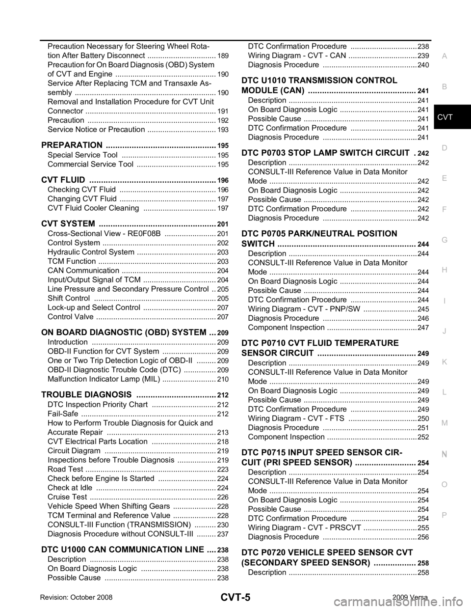
CVT
N
O
P
N
Precaution Necessary fo
r Steering Wheel Rota-
tion After Battery Disconnect ............................... ..
189
Precaution for On Board Diagnosis (OBD) System
of CVT and Engine .............................................. ..
190
Service After Replacing TCM and Transaxle As-
sembly ................................................................. ..
190
Removal and Installation Procedure for CVT Unit
Connector ............................................................ ..
191
Precaution ........................................................... ..192
Service Notice or Precaution ............................... ..193
PREPARATION .............................................. ..195
Special Service Tool ........................................... ..195
Commercial Service Tool .................................... ..195
CVT FLUID ..................................................... ..196
Checking CVT Fluid ............................................ ..196
Changing CVT Fluid ............................................ ..197
CVT Fluid Cooler Cleanin g ...................................197
CVT SYSTEM ... .............................................. ..201
Cross-Sectional View - RE0F08B ....................... ..201
Control System .................................................... ..202
Hydraulic Control System ......................................203
TCM Function ...................................................... ..203
CAN Communication ........................................... ..204
Input/Output Signal of TCM ................................. ..204
Line Pressure and Secondary Pressure Control . ..205
Shift Control ........................................................ ..205
Lock-up and Select Control ................................. ..207
Control Valve ....................................................... ..207
ON BOARD DIAGNOSTIC (OBD) SYSTEM .. ..209
Introduction ......................................................... ..209
OBD-II Function for CVT System ........................ ..209
One or Two Trip Detection Logic of OBD-II ........ ..209
OBD-II Diagnostic Trouble Code (DTC) .............. ..209
Malfunction Indicator Lamp (MIL) ........................ ..210
TROUBLE DIAGNOSIS ................................. ..212
DTC Inspection Priority Chart ............................. ..212
Fail-Safe .............................................................. ..212
How to Perform Trouble Diagnosis for Quick and
Accurate Repair ........... .........................................
213
CVT Electrical Parts Location ............................. ..218
Circuit Diagram ................................................... ..219
Inspections before Trouble Diagnosis ................. ..219
Road Test ............................................................ ..223
Check before Engine Is Started ............................224
Check at Idle ....................................................... ..224
Cruise Test .......................................................... ..226
Vehicle Speed When Shifting Gears ................... ..228
TCM Terminal and Reference Value ................... ..228
CONSULT-III Function (TRANSMISSION) ......... ..230
Diagnosis Procedu re without CONSULT-III ........ ..237
DTC U1000 CAN COMMUNICATION LINE ... ..238
Description .......................................................... ..238
On Board Diagnosis Logic .................................. ..238
Possible Cause ................................................... ..238 DTC Confirmation Procedure ..............................
..238
Wiring Diagram - CVT - CAN ............................... ..239
Diagnosis Procedure ........................................... ..240
DTC U1010 TRANSMISSION CONTROL
MODULE (CAN) .............................................. 241
Description ........................................................... ..241
On Board Diagnosis Logic ................................... ..241
Possible Cause .................................................... ..241
DTC Confirmation Procedure .............................. ..241
Diagnosis Procedure ........................................... ..241
DTC P0703 STOP LAMP SWITCH CIRCUIT . 242
Description ........................................................... ..242
CONSULT-III Reference Va lue in Data Monitor
Mode .................................................................... ..
242
On Board Diagnosis Logic ................................... ..242
Possible Cause .................................................... ..242
DTC Confirmation Procedure .............................. ..242
Diagnosis Procedure ........................................... ..242
DTC P0705 PARK/NEUTRAL POSITION
SWITCH ........................................................... 244
Description ........................................................... ..244
CONSULT-III Reference Va lue in Data Monitor
Mode .................................................................... ..
244
On Board Diagnosis Logic ................................... ..244
Possible Cause .................................................... ..244
DTC Confirmation Procedure .............................. ..244
Wiring Diagram - CVT - PNP/SW ........................ ..245
Diagnosis Procedure ........................................... ..246
Component Inspection ......................................... ..247
DTC P0710 CVT FLUID TEMPERATURE
SENSOR CIRCUIT .......................................... 249
Description ........................................................... ..249
CONSULT-III Reference Va lue in Data Monitor
Mode .................................................................... ..
249
On Board Diagnosis Logic ................................... ..249
Possible Cause .................................................... ..249
DTC Confirmation Procedure .............................. ..249
Wiring Diagram - CVT - FTS ............................... ..250
Diagnosis Procedure ........................................... ..251
Component Inspection ......................................... ..252
DTC P0715 INPUT SPEED SENSOR CIR-
CUIT (PRI SPEED SENSOR) .......................... 254
Description ........................................................... ..254
CONSULT-III Reference Va lue in Data Monitor
Mode .................................................................... ..
254
On Board Diagnosis Logic ................................... ..254
Possible Cause .................................................... ..254
DTC Confirmation Procedure .............................. ..254
Wiring Diagram - CVT - PRSCVT ........................ ..255
Diagnosis Procedure ........................................... ..256
DTC P0720 VEHICLE SPEED SENSOR CVT
(SECONDARY SPEED SENSOR) .................. 258
Description ........................................................... ..258
Page 950 of 4331
