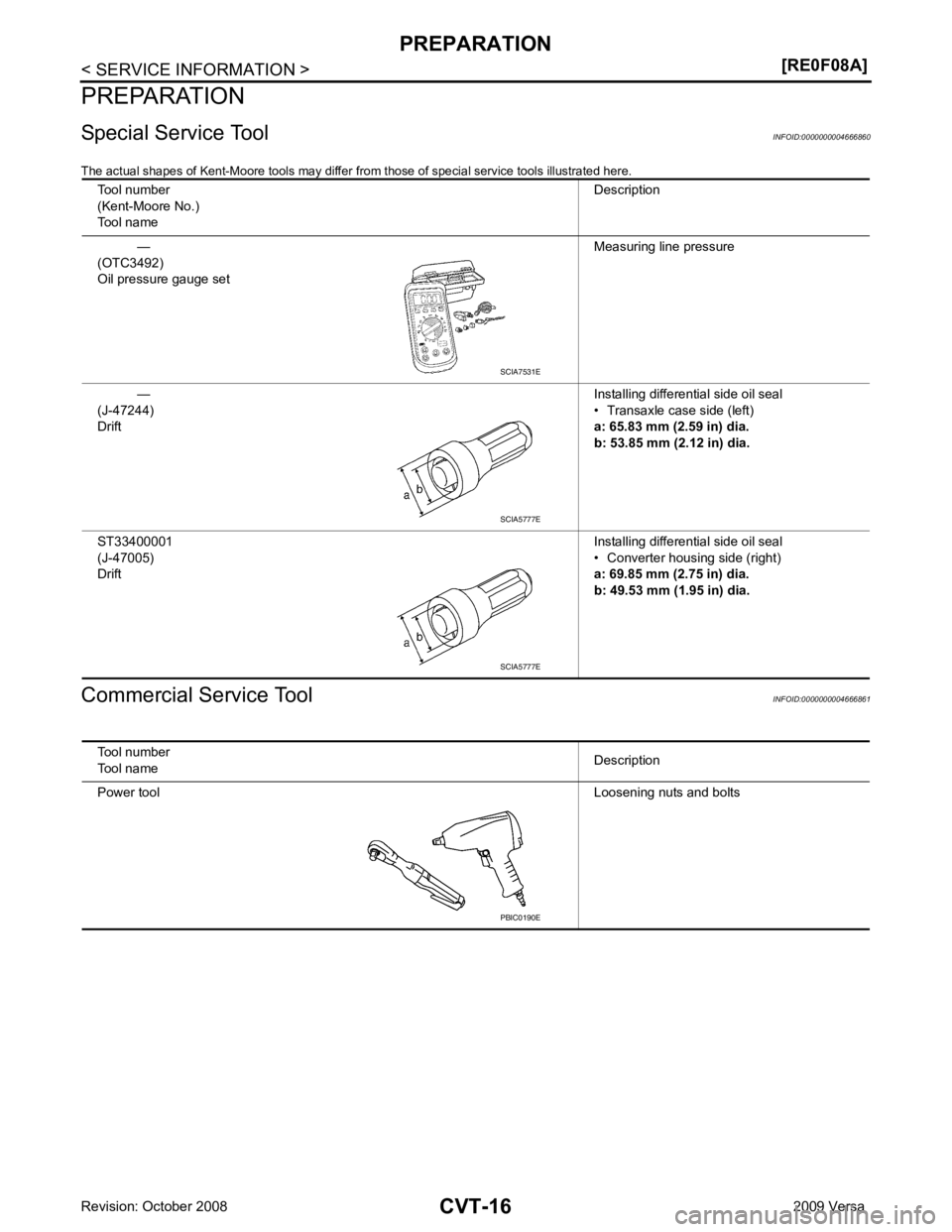
NISSAN LATIO 2009 Service Repair Manual
Manufacturer: NISSAN, Model Year: 2009, Model line: LATIO, Model: NISSAN LATIO 2009Pages: 4331, PDF Size: 58.04 MB
Page 951 of 4331

CVT
N
O
P
N
Description ..........................................................
..
293
CONSULT-III Refe rence Value in Data Monitor
Mode ................................................................... ..
293
On Board Diagnosis Logic .................................. ..293
Possible Cause ................................................... ..293
DTC Confirmation Procedure .............................. ..293
Diagnosis Procedure ........................................... ..293
DTC P1701 TRANSMISSION CONTROL
MODULE (POWER SUPPLY) ........................ ..295
Description .......................................................... ..295
On Board Diagnosis Logic .................................. ..295
Possible Cause ................................................... ..295
DTC Confirmation Procedure .............................. ..295
Wiring Diagram - CVT - POWER ........................ ..296
Diagnosis Procedure ........................................... ..297
DTC P1705 THROTTLE POSITION SENSOR ..299
Description .......................................................... ..299
CONSULT-III Refe rence Value in Data Monitor
Mode ................................................................... ..
299
On Board Diagnosis Logic .................................. ..299
Possible Cause ................................................... ..299
DTC Confirmation Procedure .............................. ..299
Diagnosis Procedure ........................................... ..299
DTC P1722 ESTM VEHICLE SPEED SIGNAL ..301
Description .......................................................... ..301
CONSULT-III Refe rence Value in Data Monitor
Mode ................................................................... ..
301
On Board Diagnosis Logic .................................. ..301
Possible Cause ................................................... ..301
DTC Confirmation Procedure .............................. ..301
Diagnosis Procedure ........................................... ..301
DTC P1723 CVT SPEED SENSOR FUNC-
TION ............................................................... ..303
Description .......................................................... ..303
On Board Diagnosis Logic .................................. ..303
Possible Cause ................................................... ..303
DTC Confirmation Procedure .............................. ..303
Diagnosis Procedure ........................................... ..303
DTC P1726 ELECTRIC THROTTLE CON-
TROL SYSTEM .............................................. ..
305
Description .......................................................... ..305
On Board Diagnosis Logic .................................. ..305
Possible Cause ................................................... ..305
DTC Confirmation Procedure .............................. ..305
Diagnosis Procedure ........................................... ..305
DTC P1740 LOCK-UP SELECT SOLENOID
VALVE CIRCUIT ............................................ ..
306
Description .......................................................... ..306
CONSULT-III Refe rence Value in Data Monitor
Mode ................................................................... ..
306
On Board Diagnosis Logic .................................. ..306
Possible Cause ................................................... ..306
DTC Confirmation Procedure .............................. ..306
Wiring Diagram - CVT - L/USSV ......................... ..307 Diagnosis Procedure ...........................................
..308
Component Inspection ......................................... ..309
DTC P1745 LINE PRESSURE CONTROL ..... 310
Description ........................................................... ..310
On Board Diagnosis Logic ................................... ..310
Possible Cause .................................................... ..310
DTC Confirmation Procedure .............................. ..310
Diagnosis Procedure ........................................... ..310
DTC P1777 STEP MOTOR - CIRCUIT ........... 311
Description ........................................................... ..311
CONSULT-III Reference Va lue in Data Monitor
Mode .................................................................... ..
311
On Board Diagnosis Logic ................................... ..311
Possible Cause .................................................... ..311
DTC Confirmation Procedure .............................. ..311
Wiring Diagram - CVT - STM ............................... ..312
Diagnosis Procedure ........................................... ..313
Component Inspection ......................................... ..314
DTC P1778 STEP MOTOR - FUNCTION ....... 315
Description ........................................................... ..315
CONSULT-III Reference Va lue in Data Monitor
Mode .................................................................... ..
315
On Board Diagnosis Logic ................................... ..315
Possible Cause .................................................... ..315
DTC Confirmation Procedure .............................. ..315
Diagnosis Procedure ........................................... ..316
OVERDRIVE CONTROL SWITCH .................. 317
Description ........................................................... ..317
CONSULT-III Reference Va lue in Data Monitor
Mode .................................................................... ..
317
Wiring Diagram - CVT - ODSW ........................... ..318
Diagnosis Procedure ........................................... ..318
Component Inspection ......................................... ..320
SHIFT POSITION INDICATOR CIRCUIT ........ 322
Description ........................................................... ..322
CONSULT-III Reference Va lue in Data Monitor
Mode .................................................................... ..
322
Diagnosis Procedure ........................................... ..322
TROUBLE DIAGNOSIS FOR SYMPTOMS .... 323
Wiring Diagram - CVT - NONDTC ....................... ..323
O/D OFF Indicator Lamp Does Not Come On ..... ..325
Engine Cannot Be Started in "P" and "N" Position ..327
In "P" Position, Vehicle Moves Forward or Back-
ward When Pushed ............................................. ..
327
In "N" Position, Vehicle Moves ............................ ..328
Large Shock "N" → "R" Position .......................... ..328
Vehicle Does Not Creep Backward in "R" Position ..329
Vehicle Does Not Creep Forward in "D" or "L" Po-
sition .................................................................... ..
330
Vehicle Speed Does Not Change in "L" Position . ..331
Vehicle Speed Does Not Change in overdrive-off
mode .................................................................... ..
332
Vehicle Speed Does Not Change in "D" Position .. 333
Vehicle Does Not Decelerate by Engine Brake ... ..333
Page 952 of 4331

Page 953 of 4331
CVT
N
O P
SERVICE INFORMATION
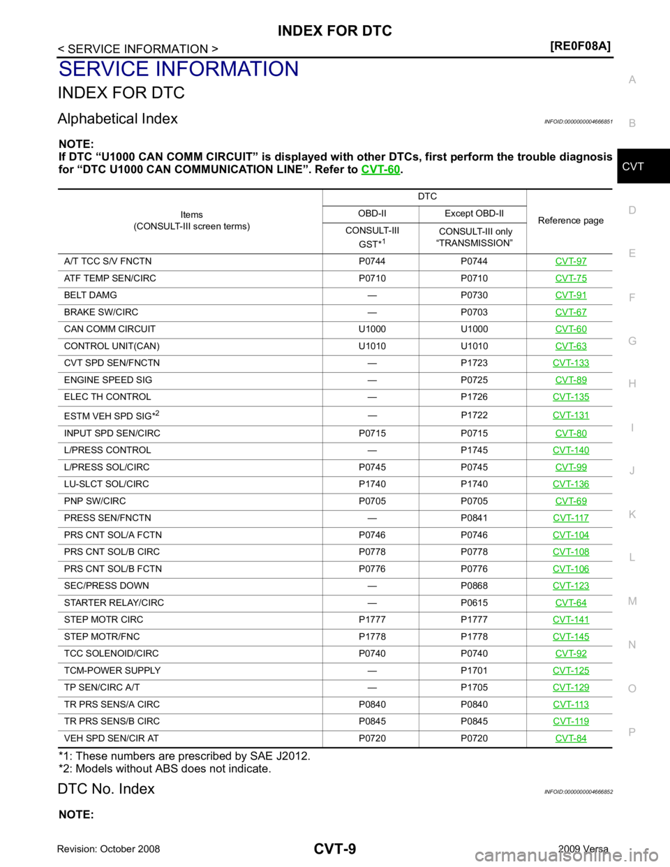
INDEX FOR DTC
Alphabetical Index INFOID:0000000004666851
NOTE:
If DTC “U1000 CAN COMM CIRCUIT” is displayed with other DTCs, first perform the trouble diagnosis
for “DTC U1000 CAN COMMUNICATION LINE”. Refer to CVT-60 .
*1: These numbers are prescribed by SAE J2012.
*2: Models without ABS does not indicate.
DTC No. Index INFOID:0000000004666852
NOTE: Items
(CONSULT-III screen terms) DTC
Reference page
OBD-II Except OBD-II
CONSULT-III GST* 1 CONSULT-III only
“TRANSMISSION”
A/T TCC S/V FNCTN P0744 P0744 CVT-97ATF TEMP SEN/CIRC P0710 P0710
CVT-75BELT DAMG — P0730
CVT-91BRAKE SW/CIRC — P0703
CVT-67CAN COMM CIRCU
IT U1000 U1000 CVT-60CONTROL UNIT(CAN) U1010 U1010
CVT-63CVT SPD SEN/FNCTN — P1723
CVT-133ENGINE SPEED SIG — P0725
CVT-89ELEC TH CONTROL — P1726
CVT-135ESTM VEH SPD SIG*
2
— P1722CVT-131INPUT SPD SEN/CIRC P0715 P0715
CVT-80L/PRESS CONTROL — P1745
CVT-140L/PRESS SOL/CIRC P0745 P0745
CVT-99LU-SLCT SOL/CIRC P1740 P1740
CVT-136PNP SW/CIRC P0705 P0705
CVT-69PRESS SEN/FNCTN — P0841
CVT-117PRS CNT SOL/A FCTN P0746 P0746
CVT-104PRS CNT SOL/B CIRC P0778 P0778
CVT-108PRS CNT SOL/B FCTN P0776 P0776
CVT-106SEC/PRESS DOWN — P0868
CVT-123STARTER RELAY/CIRC — P0615
CVT-64STEP MOTR CIRC P1777 P1777
CVT-141STEP MOTR/FNC P1778 P1778
CVT-145TCC SOLENOID/CIRC P0740 P0740
CVT-92TCM-POWER SUPPLY — P1701
CVT-125TP SEN/CIRC A/T — P1705
CVT-129TR PRS SENS/A CIRC P0840 P0840
CVT-113TR PRS SENS/B CIRC P0845 P0845
CVT-119VEH SPD SEN/CIR AT P0720 P0720
CVT-84
Page 954 of 4331
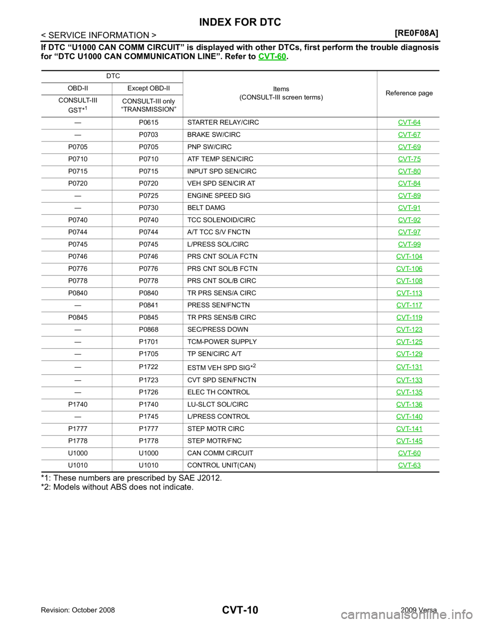
.
*1: These numbers are pr escribed by SAE J2012.
*2: Models without ABS does not indicate. DTC
Items
(CONSULT-III screen terms) Reference page
OBD-II Except OBD-II
CONSULT-III GST* 1 CONSULT-III only
“TRANSMISSION”
— P0615 STARTER RELAY/CIRC CVT-64— P0703 BRAKE SW/CIRC
CVT-67P0705 P0705 PNP SW/CIRC
CVT-69P0710 P0710 ATF TEMP SEN/CIRC
CVT-75P0715 P0715 INPUT SPD SEN/CIRC
CVT-80P0720 P0720 VEH SPD SEN/CIR AT
CVT-84— P0725 ENGINE SPEED SIG
CVT-89— P0730 BELT DAMG
CVT-91P0740 P0740 TCC SOLENOID/CIRC
CVT-92P0744 P0744 A/T TCC S/V FNCTN
CVT-97P0745 P0745 L/PRESS SOL/CIRC
CVT-99P0746 P0746 PRS CNT SOL/A FCTN
CVT-104P0776 P0776 PRS CNT SOL/B FCTN
CVT-106P0778 P0778 PRS CNT SOL/B CIRC
CVT-108P0840 P0840 TR PRS SENS/A CIRC
CVT-113— P0841 PRESS SEN/FNCTN
CVT-117P0845 P0845 TR PRS SENS/B CIRC
CVT-119— P0868 SEC/PRESS DOWN
CVT-123— P1701 TCM-POWER SUPPLY
CVT-125— P1705 TP SEN/CIRC A/T
CVT-129— P1722
ESTM VEH SPD SIG*2
CVT-131— P1723 CVT SPD SEN/FNCTN
CVT-133— P1726 ELEC TH CONTROL
CVT-135P1740 P1740 LU-SLCT SOL/CIRC
CVT-136— P1745 L/PRESS CONTROL
CVT-140P1777 P1777 STEP MOTR CIRC
CVT-141P1778 P1778 STEP MOTR/FNC
CVT-145U1000 U1000 CAN COMM CIRCUIT
CVT-60U1010 U1010 CONTROL UNIT(CAN)
CVT-63
Page 955 of 4331
CVT
N
O P
PRECAUTIONS
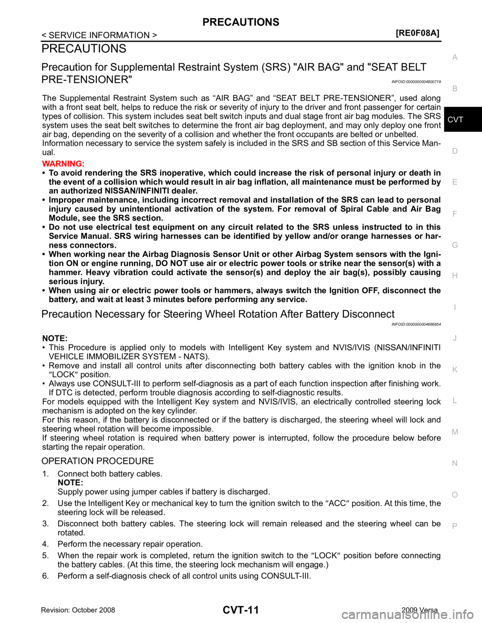
Precaution for Supplemental Restraint System (SRS) "AIR BAG" and "SEAT BELT
PRE-TENSIONER" INFOID:0000000004800719
The Supplemental Restraint System such as “A IR BAG” and “SEAT BELT PRE-TENSIONER”, used along
with a front seat belt, helps to reduce the risk or severi ty of injury to the driver and front passenger for certain
types of collision. This system includes seat belt switch inputs and dual stage front air bag modules. The SRS
system uses the seat belt switches to determine the front air bag deployment, and may only deploy one front
air bag, depending on the severity of a collision and w hether the front occupants are belted or unbelted.
Information necessary to service the system safely is included in the SRS and SB section of this Service Man-
ual.
WARNING:
• To avoid rendering the SRS inoper ative, which could increase the risk of personal injury or death in
the event of a collision which would result in air bag inflation, all maintenance must be performed by
an authorized NISSAN/INFINITI dealer.
• Improper maintenance, including in correct removal and installation of the SRS can lead to personal
injury caused by unintentional act ivation of the system. For removal of Spiral Cable and Air Bag
Module, see the SRS section.
• Do not use electrical test equipm ent on any circuit related to the SRS unless instructed to in this
Service Manual. SRS wiring harnesses can be identi fied by yellow and/or orange harnesses or har-
ness connectors.
• When working near the Airbag Diagnosis Sensor Un it or other Airbag System sensors with the Igni-
tion ON or engine running, DO NOT use air or el ectric power tools or strike near the sensor(s) with a
hammer. Heavy vibration could activate the sensor( s) and deploy the air bag(s), possibly causing
serious injury.
• When using air or electric power tools or hammers , always switch the Ignition OFF, disconnect the
battery, and wait at least 3 minutes before performing any service.
Precaution Necessary for Steering Wh eel Rotation After Battery Disconnect
INFOID:0000000004666854
NOTE:
• This Procedure is applied only to models with Intell igent Key system and NVIS/IVIS (NISSAN/INFINITI
VEHICLE IMMOBILIZER SYSTEM - NATS).
• Remove and install all control units after disconnecti ng both battery cables with the ignition knob in the
″ LOCK ″ position.
• Always use CONSULT-III to perform self-diagnosis as a part of each function inspection after finishing work.
If DTC is detected, perform trouble diagnosis according to self-diagnostic results.
For models equipped with the Intelligent Key system and NVIS/IVIS, an electrically controlled steering lock
mechanism is adopted on the key cylinder.
For this reason, if the battery is disconnected or if the battery is discharged, the steering wheel will lock and
steering wheel rotation will become impossible.
If steering wheel rotation is required when battery pow er is interrupted, follow the procedure below before
starting the repair operation.
OPERATION PROCEDURE 1. Connect both battery cables. NOTE:
Supply power using jumper cables if battery is discharged.
2. Use the Intelligent Key or mechanical key to turn the ignition switch to the ″ACC ″ position. At this time, the
steering lock will be released.
3. Disconnect both battery cables. The steering lock will remain released and the steering wheel can be
rotated.
4. Perform the necessary repair operation.
5. When the repair work is completed, return the ignition switch to the ″LOCK ″ position before connecting
the battery cables. (At this time, the steering lock mechanism will engage.)
6. Perform a self-diagnosis check of al l control units using CONSULT-III.
Page 956 of 4331
Page 957 of 4331
CVT
N
O P
Do not start engine.
6. Select “SELF-DIAG RESULTS”.
7. Shift the selector lever to “R” position.
8. Depress slightly the accelerator pedal (Pedal angle: 2/8) while depressing the brake pedal.
9. Perform “ERASE”.
10. Shift the selector lever to “R” position afte r replacing TCM. Turn the ignition switch OFF.
11. Wait approximately 10 minutes after turning the ignition switch OFF.
12. Turn the ignition switch ON while shifting the selector lever to “R” position. CAUTION:
Do not start engine.
13. Select “CALIBRATION DATA”.
14. Check that the value on “CALIBRATION DATA” is same as the data after erasing "Calibration Data". • Restart the procedure from step 3 if the values are not same.
15. Shift the selector lever to “P” position.
16. Check that the shift position indicator in the combi nation meter turns ON (It indicates approximately 1 or 2
seconds after shifting the selector lever to “P” position.)
• Check the following items if the shift position indicato r does not turn ON. Repair or replace the shift posi-
tion indicator if necessary.
- The harness between TCM and ROM ASSY in the transaxle assembly is open or short.
- Cable disconnected, loosen, or bent from the connector housing.
- Power supply and ground of TCM. Refer to CVT-125, " Description " .
PATTERN C 1. Replace the transaxle assembly first, and then replace TCM.
2. Perform the service of “PATTERN A”. (Perform the service of “Pattern B” if TCM is replaced first.)
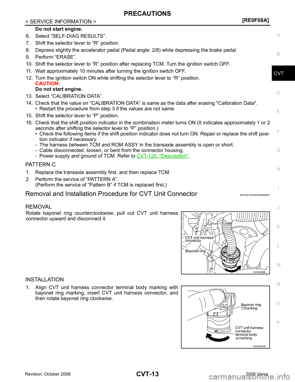
Removal and Installation Proc edure for CVT Unit Connector INFOID:0000000004666857
REMOVAL Rotate bayonet ring counterclockwise, pull out CVT unit harness
connector upward and disconnect it.
INSTALLATION 1. Align CVT unit harness connector terminal body marking with bayonet ring marking, insert CVT unit harness connector, and
then rotate bayonet ring clockwise.
Page 958 of 4331
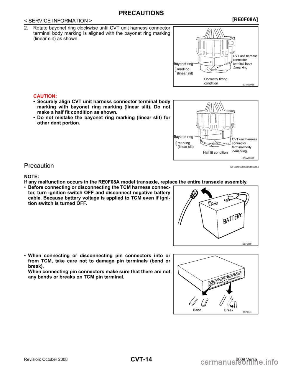
SCIA2099E
SEF291H
Page 959 of 4331
![NISSAN LATIO 2009 Service Repair Manual PRECAUTIONS
CVT-15
< SERVICE INFORMATION >
[RE0F08A] D
E
F
G H
I
J
K L
M A
B CVT
N
O P
•
Before replacing TCM, perform TCM input/output signal
inspection and make sure whether TCM functions pr NISSAN LATIO 2009 Service Repair Manual PRECAUTIONS
CVT-15
< SERVICE INFORMATION >
[RE0F08A] D
E
F
G H
I
J
K L
M A
B CVT
N
O P
•
Before replacing TCM, perform TCM input/output signal
inspection and make sure whether TCM functions pr](/img/5/57359/w960_57359-958.png)
PRECAUTIONS
CVT-15
< SERVICE INFORMATION >
[RE0F08A] D
E
F
G H
I
J
K L
M A
B CVT
N
O P
•
Before replacing TCM, perform TCM input/output signal
inspection and make sure whether TCM functions properly or
not. CVT-49, " TCM Terminal and Reference Value " .
• After performing each TROUBL E DIAGNOSIS, perform “DTC
Confirmation Procedure”.
If the repair is completed the DTC should not be displayed in
the “DTC Confirmation Procedure”.
• Always use the specified br and of CVT fluid. Refer to MA-14, " Flu-
ids and Lubricants " .
• Use lint-free paper, not cloth rags, during work.
• After replacing the CVT fluid, dispose of the waste oil using the methods prescribed by law, ordinance, etc.
Service Notice or Precaution INFOID:0000000004666859
CVT FLUID COOLER SERVICE If CVT fluid contains friction material (clutches, brakes , etc.), or if an CVT is replaced, inspect and clean the
CVT fluid cooler mounted in the radiator or replace t he radiator. Flush cooler lines using cleaning solvent and
compressed air after repair. For CVT fluid cooler cleaning procedure, refer to CVT-18, " CVT Fluid Cooler
Cleaning " . For radiator replacement, refer to
CO-38 .
OBD-II SELF-DIAGNOSIS • CVT self-diagnosis is performed by the TCM in comb ination with the ECM. The results can be read through
the blinking pattern of the malfunction indi cator lamp (MIL). Refer to the table on CVT-51, " CONSULT-III
Function (TRANSMISSION) " for the indicator used to display each self-diagnostic result.
• The self-diagnostic results indicated by the MIL ar e automatically stored in both the ECM and TCM memo-
ries.
Always perform the procedure on CVT-30, " OBD-II Diagnostic Trouble Code (DTC) " to complete the
repair and avoid unnecessary blinking of the MIL.
For details of OBD-II, refer to EC-541, " Introduction " .
• Certain systems and components, especially those re lated to OBD, may use the new style slide-lock-
ing type harness connector. For descripti on and how to disconnect, refer to PG-64 . MEF040DA
SEF217U
Page 960 of 4331
