display NISSAN LATIO 2011 Service Repair Manual
[x] Cancel search | Manufacturer: NISSAN, Model Year: 2011, Model line: LATIO, Model: NISSAN LATIO 2011Pages: 3787, PDF Size: 78.35 MB
Page 959 of 3787
BRC-70
< SERVICE INFORMATION >[VDC/TCS/ABS]
TROUBLE DIAGNOSIS FOR
SELF-DIAGNOSTIC ITEMS
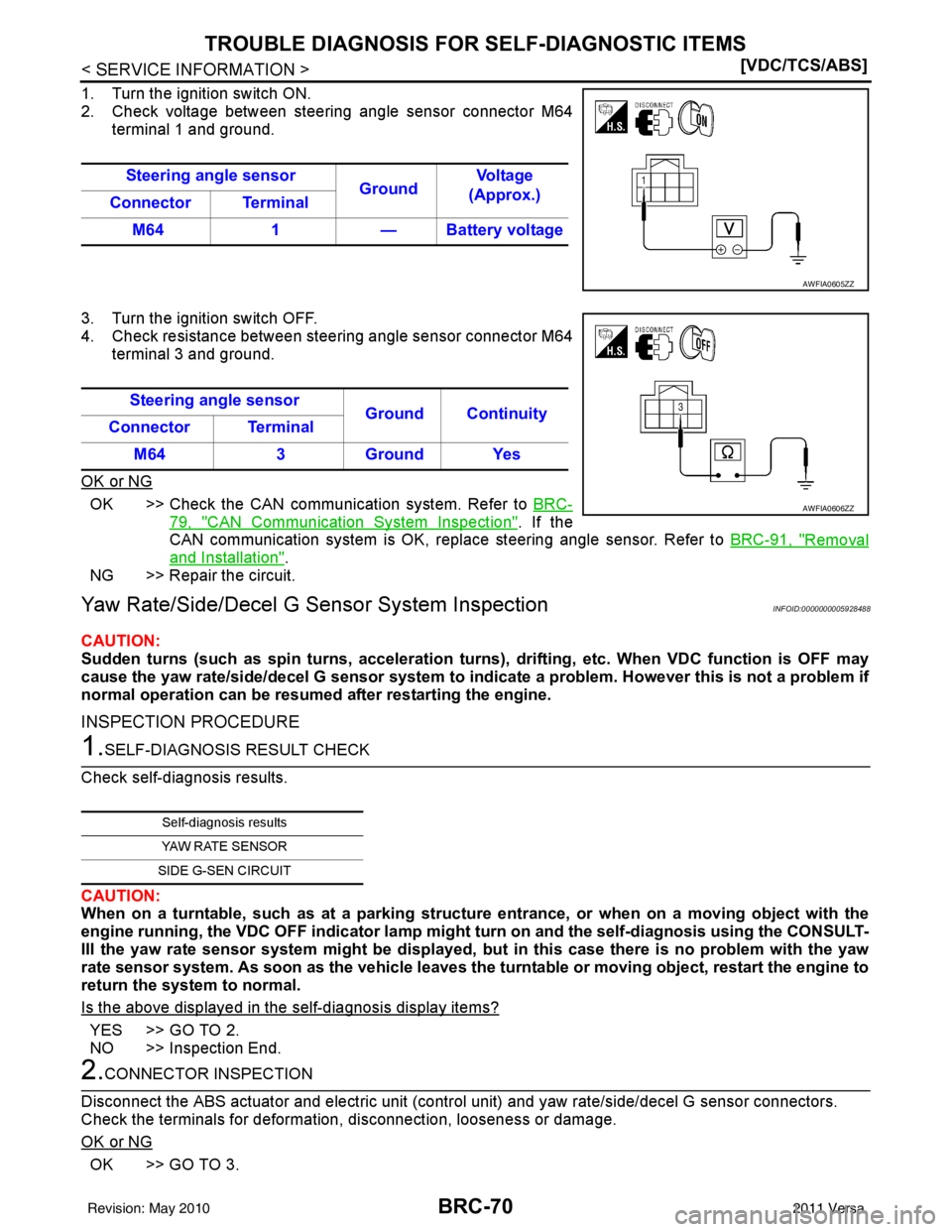
1. Turn the ignition switch ON.
2. Check voltage between steering angle sensor connector M64
terminal 1 and ground.
3. Turn the ignition switch OFF.
4. Check resistance between steering angle sensor connector M64 terminal 3 and ground.
OK or NG
OK >> Check the CAN communication system. Refer to BRC-
79, "CAN Communication System Inspection". If the
CAN communication system is OK, replace steering angle sensor. Refer to BRC-91, "
Removal
and Installation".
NG >> Repair the circuit.
Yaw Rate/Side/Decel G Sensor System InspectionINFOID:0000000005928488
CAUTION:
Sudden turns (such as spin turns, acceleration turns), drifting, etc. When VDC function is OFF may
cause the yaw rate/side/decel G sensor system to indi cate a problem. However this is not a problem if
normal operation can be resumed after restarting the engine.
INSPECTION PROCEDURE
1.SELF-DIAGNOSIS RESULT CHECK
Check self-diagnosis results.
CAUTION:
When on a turntable, such as at a parking structure entrance, or when on a moving object with the
engine running, the VDC OFF indicator lamp migh t turn on and the self-diagnosis using the CONSULT-
III the yaw rate sensor system might be displayed, but in this case there is no problem with the yaw
rate sensor system. As soon as the vehicle leaves the turntable or moving object, restart the engine to
return the system to normal.
Is the above displayed in the self-diagnosis display items?
YES >> GO TO 2.
NO >> Inspection End.
2.CONNECTOR INSPECTION
Disconnect the ABS actuator and electric unit (contro l unit) and yaw rate/side/decel G sensor connectors.
Check the terminals for deformation, disconnection, looseness or damage.
OK or NG
OK >> GO TO 3. Steering angle sensor
GroundVo l ta g e
(Approx.)
Connector Terminal
M64 1— Battery voltage
AWFIA0605ZZ
Steering angle sensor
Ground Continuity
Connector Terminal
M64 3 Ground Yes
AWFIA0606ZZ
Self-diagnosis results
YAW RATE SENSOR
SIDE G-SEN CIRCUIT
Revision: May 2010 2011 Versa
Page 961 of 3787
BRC-72
< SERVICE INFORMATION >[VDC/TCS/ABS]
TROUBLE DIAGNOSIS FOR
SELF-DIAGNOSTIC ITEMS
2. Select “YAW RATE SEN”, “SIDE G-SENSOR” in “Data Monitor” and check Yaw rate/side/decel G sensor
signal.
Is the inspection result normal?
YES >> Replace ABS actuator and electric unit (control unit). Refer to BRC-89, "Removal and Installa-
tion".
NO >> Replace Yaw rate/side/decel G sensor. Refer to BRC-92, "
Removal and Installation".
Solenoid and VDC Change-Over Valve System InspectionINFOID:0000000005928489
INSPECTION PROCEDURE
1.SELF-DIAGNOSIS RESULT CHECK
Check self-diagnosis results.
Is the above displayed in the self-diagnosis display items?
YES >> GO TO 2.
NO >> Inspection End.
2.CONNECTOR INSPECTION
1. Disconnect ABS actuator and electric unit (control unit) connector.
2. Check the terminals for deformati on, disconnection, looseness or damage.
OK or NG
OK >> GO TO 3.
NG >> Repair or replace as necessary.
3.CHECKING SOLENOID POWER AND GROUND
Vehicle condition Yaw rate sensor (Data monitor) Side G sensor (Data monitor)
Stopped Approx. 0 d/s
Approx. 0 m/s
2
Turning right Negative valueNegative value
Turning left Positive valuePositive value
Self-diagnosis results
FR LH IN ABS SOL
FR LH OUT ABS SOL RR RH IN ABS SOL
RR RH OUT ABS SOL FR RH IN ABS SOL
FR RH OUT ABS SOL RR LH IN ABS SOL
RR LH OUT ABS SOL USV LINE [FL-RR]
USV LINE [FR-RL]
HSV LINE [FL-RR]
HSV LINE [FR-RL] MAIN RELAY
Revision: May 2010 2011 Versa
Page 962 of 3787
TROUBLE DIAGNOSIS FOR SELF-DIAGNOSTIC ITEMS
BRC-73
< SERVICE INFORMATION > [VDC/TCS/ABS]
C
D
E
G H
I
J
K L
M A
B
BRC
N
O P
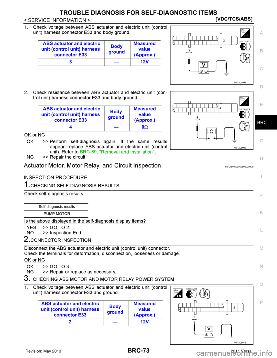
1. Check voltage between ABS actuator and electric unit (control unit) harness connector E33 and body ground.
2. Check resistance between ABS actuator and electric unit (con- trol unit) harness connector E33 and body ground.
OK or NG
OK >> Perform self-diagnosis again. If the same results appear, replace ABS actuator and electric unit (control
unit). Refer to BRC-89, "
Removal and Installation".
NG >> Repair the circuit.
Actuator Motor, Motor Relay, and Circuit InspectionINFOID:0000000005928490
INSPECTION PROCEDURE
1.CHECKING SELF-DIAGNOSIS RESULTS
Check self-diagnosis results.
Is the above displayed in the self-diagnosis display items?
YES >> GO TO 2.
NO >> Inspection End.
2.CONNECTOR INSPECTION
Disconnect the ABS actuator and electr ic unit (control unit) connector.
Check the terminals for deformation, disconnection, looseness or damage.
OK or NG
OK >> GO TO 3.
NG >> Repair or replace as necessary.
3.CHECKING ABS MOTOR AND MOTOR RELAY POWER SYSTEM
1. Check voltage between ABS actuator and electric unit (control unit) harness connector E33 and ground. ABS actuator and electric
unit (control unit) harness connector E33 Body
ground Measured
value
(Approx.)
3 — 12V
WFIA0499E
ABS actuator and electric
unit (control unit) harness connector E33 Body
ground Measured
value
(Approx.)
4—0 Ω
WFIA0500E
Self-diagnosis results
PUMP MOTOR
ABS actuator and electric
unit (control unit) harness connector E33 Body
ground Measured
value
(Approx.)
2 — 12V
WFIA0501E
Revision: May 2010 2011 Versa
Page 963 of 3787
BRC-74
< SERVICE INFORMATION >[VDC/TCS/ABS]
TROUBLE DIAGNOSIS FOR
SELF-DIAGNOSTIC ITEMS
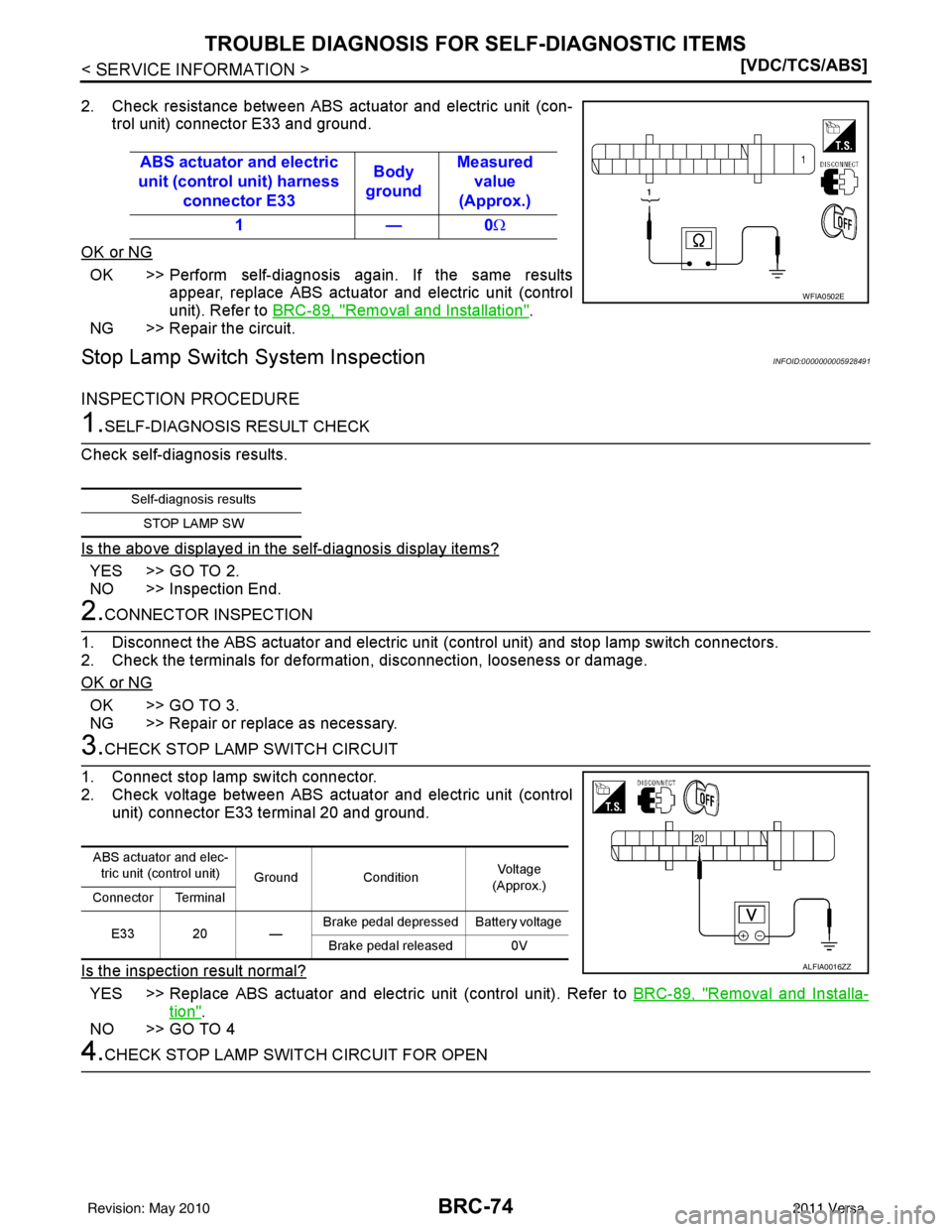
2. Check resistance between ABS actuator and electric unit (con-
trol unit) connector E33 and ground.
OK or NG
OK >> Perform self-diagnosis again. If the same results appear, replace ABS actuator and electric unit (control
unit). Refer to BRC-89, "
Removal and Installation".
NG >> Repair the circuit.
Stop Lamp Switch System InspectionINFOID:0000000005928491
INSPECTION PROCEDURE
1.SELF-DIAGNOSIS RESULT CHECK
Check self-diagnosis results.
Is the above displayed in the self-diagnosis display items?
YES >> GO TO 2.
NO >> Inspection End.
2.CONNECTOR INSPECTION
1. Disconnect the ABS actuator and electric unit (control unit) and stop lamp switch connectors.
2. Check the terminals for deformati on, disconnection, looseness or damage.
OK or NG
OK >> GO TO 3.
NG >> Repair or replace as necessary.
3.CHECK STOP LAMP SWITCH CIRCUIT
1. Connect stop lamp switch connector.
2. Check voltage between ABS actuator and electric unit (control unit) connector E33 terminal 20 and ground.
Is the inspection result normal?
YES >> Replace ABS actuator and electric unit (control unit). Refer to BRC-89, "Removal and Installa-
tion".
NO >> GO TO 4
4.CHECK STOP LAMP SWITCH CIRCUIT FOR OPEN ABS actuator and electric
unit (control unit) harness connector E33 Body
ground Measured
value
(Approx.)
1—0 Ω
WFIA0502E
Self-diagnosis results
STOP LAMP SW
ABS actuator and elec-tric unit (control unit) Ground Condition Vol tag e
(Approx.)
Connector Terminal
E33 20 — Brake pedal depressed Battery voltage
Brake pedal released 0V
ALFIA0016ZZ
Revision: May 2010 2011 Versa
Page 964 of 3787
TROUBLE DIAGNOSIS FOR SELF-DIAGNOSTIC ITEMS
BRC-75
< SERVICE INFORMATION > [VDC/TCS/ABS]
C
D
E
G H
I
J
K L
M A
B
BRC
N
O P
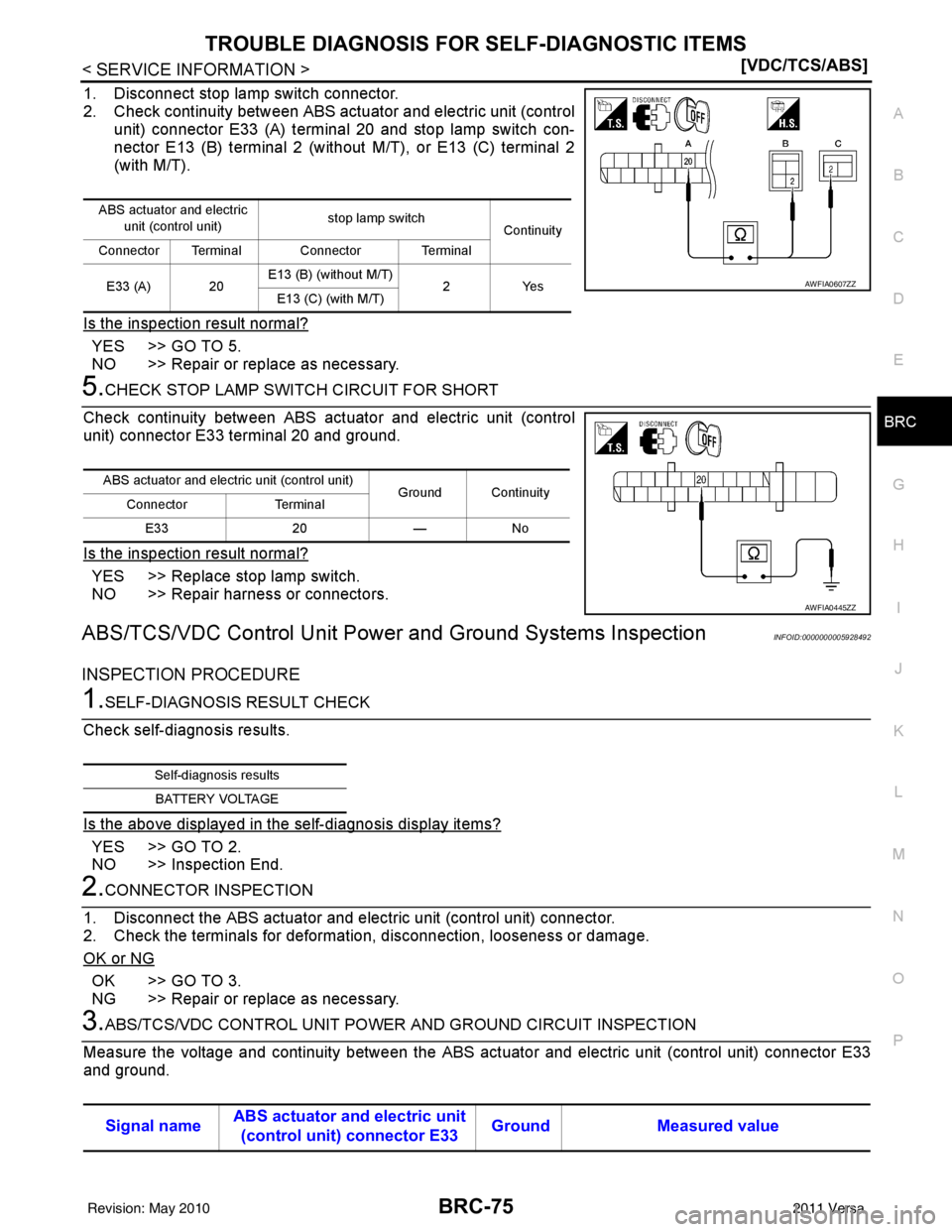
1. Disconnect stop lamp switch connector.
2. Check continuity between ABS actuator and electric unit (control unit) connector E33 (A) terminal 20 and stop lamp switch con-
nector E13 (B) terminal 2 (without M/T), or E13 (C) terminal 2
(with M/T).
Is the inspection result normal?
YES >> GO TO 5.
NO >> Repair or replace as necessary.
5.CHECK STOP LAMP SWITCH CIRCUIT FOR SHORT
Check continuity between ABS act uator and electric unit (control
unit) connector E33 terminal 20 and ground.
Is the inspection result normal?
YES >> Replace stop lamp switch.
NO >> Repair harness or connectors.
ABS/TCS/VDC Control Unit Powe r and Ground Systems InspectionINFOID:0000000005928492
INSPECTION PROCEDURE
1.SELF-DIAGNOSIS RESULT CHECK
Check self-diagnosis results.
Is the above displayed in the self-diagnosis display items?
YES >> GO TO 2.
NO >> Inspection End.
2.CONNECTOR INSPECTION
1. Disconnect the ABS actuator and elec tric unit (control unit) connector.
2. Check the terminals for deformation, disconnection, looseness or damage.
OK or NG
OK >> GO TO 3.
NG >> Repair or replace as necessary.
3.ABS/TCS/VDC CONTROL UNIT POWER AND GROUND CIRCUIT INSPECTION
Measure the voltage and continuity between the ABS act uator and electric unit (control unit) connector E33
and ground.
ABS actuator and electric
unit (control unit) stop lamp switch
Continuity
Connector Terminal Connector Terminal
E33 (A) 20 E13 (B) (without M/T)
2Yes
E13 (C) (with M/T)
AWFIA0607ZZ
ABS actuator and electric unit (control unit)
Ground Continuity
Connector Terminal
E33 20 — No
AWFIA0445ZZ
Self-diagnosis resultsBATTERY VOLTAGE
Signal name ABS actuator and electric unit
(control unit) connector E33 Ground Measured value
Revision: May 2010
2011 Versa
Page 965 of 3787
BRC-76
< SERVICE INFORMATION >[VDC/TCS/ABS]
TROUBLE DIAGNOSIS FOR
SELF-DIAGNOSTIC ITEMS
OK or NG
OK >> Check the battery for loose terminals, low voltage, etc. Repair as necessary.
NG >> Repair the circuit.
Brake Fluid Level Switch System InspectionINFOID:0000000005928493
INSPECTION PROCEDURE
1.SELF-DIAGNOSIS RESULT CHECK
1. Check the brake reservoir tank fluid level. If the level is low, add brake fluid.
2. Erase the self-diagnosis results and check the self-diagnosis results.
Is the above displayed in the self-diagnosis display items?
YES >> GO TO 2.
NO >> Inspection End.
2.CONNECTOR INSPECTION
1. Disconnect the ABS actuator and electric unit (cont rol unit) and brake fluid level switch connectors.
2. Check the terminals for deformati on, disconnection, looseness or damage.
OK or NG
OK >> GO TO 3.
NG >> Repair or replace as necessary.
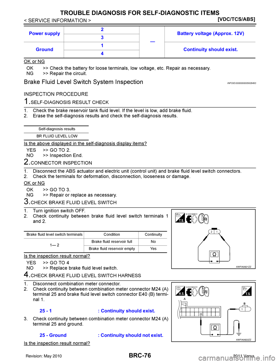
3.CHECK BRAKE FLUID LEVEL SWITCH
1. Turn ignition switch OFF.
2. Check continuity between brake fluid level switch terminals 1 and 2.
Is the inspection result normal?
YES >> GO TO 4
NO >> Replace brake fluid level switch.
4.CHECK BRAKE FLUID LEVEL SWITCH HARNESS
1. Disconnect combination meter connector.
2. Check continuity between combination meter connector M24 (A) terminal 25 and brake fluid level switch connector E40 (B) termi-
nal 1.
3. Check continuity between combination meter connector M24 (A) terminal 25 and ground.
Is the inspection result normal?
Power supply 2
—Battery voltage (Approx. 12V)
3
Ground 1
Continuity should exist.
4
Self-diagnosis results
BR FLUID LEVEL LOW
Brake fluid level switch terminals ConditionContinuity
1— 2 Brake fluid reservoir full No
Brake fluid reservoir empty Yes
AWFIA0621ZZ
25 - 1 : Continuity should exist.
25 - Ground : Continuity should not exist.
AWFIA0622ZZ
Revision: May 2010 2011 Versa
Page 966 of 3787
TROUBLE DIAGNOSIS FOR SELF-DIAGNOSTIC ITEMS
BRC-77
< SERVICE INFORMATION > [VDC/TCS/ABS]
C
D
E
G H
I
J
K L
M A
B
BRC
N
O P
YES >> GO TO 5
NO >> Repair or replace malfunctioning components.
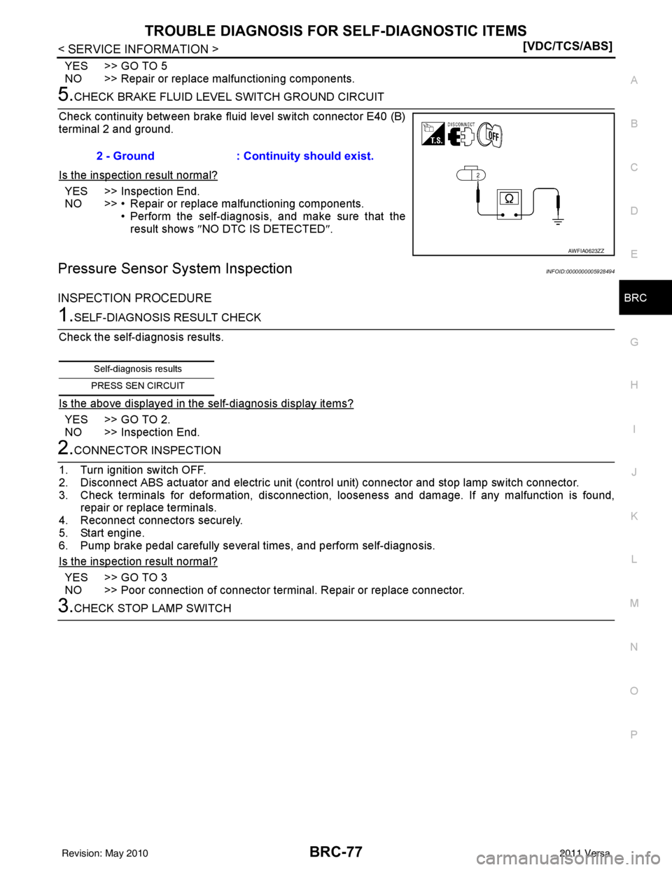
5.CHECK BRAKE FLUID LEVE L SWITCH GROUND CIRCUIT
Check continuity between brake fluid level switch connector E40 (B)
terminal 2 and ground.
Is the inspection result normal?
YES >> Inspection End.
NO >> • Repair or replace malfunctioning components. • Perform the self-diagnosis, and make sure that the
result shows ″NO DTC IS DETECTED ″.
Pressure Sensor System InspectionINFOID:0000000005928494
INSPECTION PROCEDURE
1.SELF-DIAGNOSIS RESULT CHECK
Check the self-diagnosis results.
Is the above displayed in the self-diagnosis display items?
YES >> GO TO 2.
NO >> Inspection End.
2.CONNECTOR INSPECTION
1. Turn ignition switch OFF.
2. Disconnect ABS actuator and elec tric unit (control unit) connector and stop lamp switch connector.
3. Check terminals for deformation, disconnection, looseness and damage. If any malfunction is found, repair or replace terminals.
4. Reconnect connectors securely.
5. Start engine.
6. Pump brake pedal carefully several times, and perform self-diagnosis.
Is the inspection result normal?
YES >> GO TO 3
NO >> Poor connection of connector terminal. Repair or replace connector.
3.CHECK STOP LAMP SWITCH 2 - Ground : Continuity should exist.
AWFIA0623ZZ
Self-diagnosis results
PRESS SEN CIRCUIT
Revision: May 2010 2011 Versa
Page 968 of 3787
TROUBLE DIAGNOSIS FOR SELF-DIAGNOSTIC ITEMS
BRC-79
< SERVICE INFORMATION > [VDC/TCS/ABS]
C
D
E
G H
I
J
K L
M A
B
BRC
N
O P
Check the self-diagnosis results.
Is the above displayed in the self-diagnosis display items?
YES >> GO TO 2.
NO >> Inspection End.
2.CONNECTOR INSPECTION
1. Disconnect the ABS actuator and el ectric unit (control unit) and brake fluid level switch connectors.
2. Check the terminals for deformation, disconnection, looseness or damage.
OK or NG
OK >> GO TO 3.
NG >> Repair or replace as necessary.
3.CHECK TRANSMISSION RANGE SWITCH
Perform transmission range switch inspection. Refer to AT-94, "
Component Inspection" (with A/T) or CVT-65,
"Component Inspection" (with CVT).
Is the inspection result normal?
YES >> Replace ABS actuator and electr ic unit (control unit). Refer to BRC-89, "Removal and Installa-
tion".
NO >> Repair or replace malfunctioning components.
CAN Communication System InspectionINFOID:0000000005928496
INSPECTION PROCEDURE
1.SELF-DIAGNOSIS RESULT CHECK
Check the self-diagnosis results.
Is the above displayed in the self-diagnosis display items?
YES >> GO TO 2.
NO >> Inspection End.
2.CHECK CONNECTOR
1. Disconnect the ABS actuator and electric unit (control unit) connector, and check the terminals for defor- mation, disconnection, looseness, and so on. If there is a malfunction, repair or replace the terminals.
2. Reconnect connector to perform self-diagnosis. Refer to BRC-60, "
CONSULT-III Function (ABS)".
Is
“CAN COMM CIRCUIT” displayed in the self-diagnosis display items?
YES >> Refer to LAN-17, "Trouble Diagnosis Flow Chart".
NO >> Connector terminal connection is loose, damaged, open, or shorted.
Component InspectionINFOID:0000000005928497
VDC OFF SWITCH
Self-diagnosis results
PNP POS SIG
Self-diagnosis results
ST ANG SEN COM CIR CAN COMM CIRCUIT
Revision: May 2010 2011 Versa
Page 973 of 3787
BRC-84
< SERVICE INFORMATION >[VDC/TCS/ABS]
TROUBLE DIAGNOSES FOR SYMPTOMS
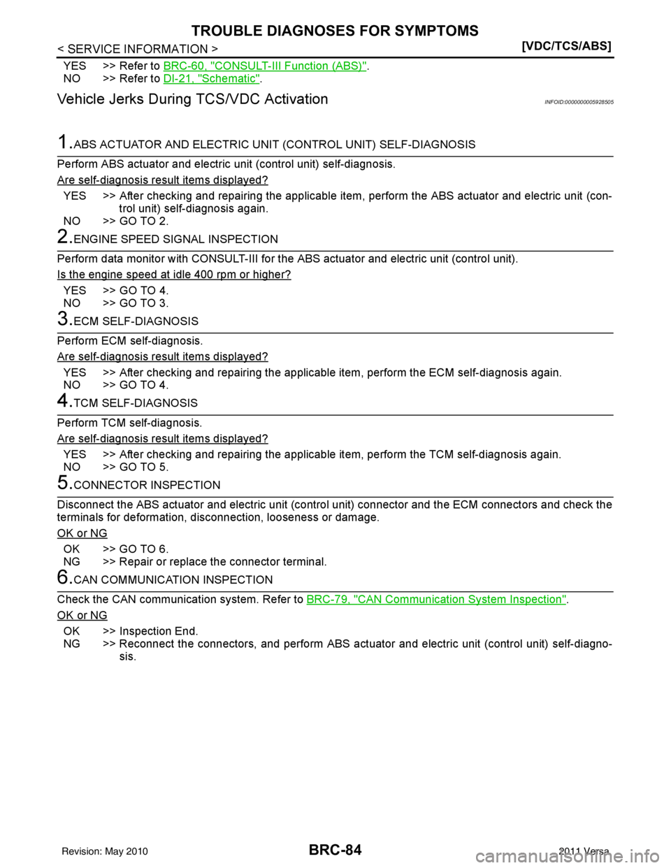
YES >> Refer to BRC-60, "CONSULT-III Function (ABS)".
NO >> Refer to DI-21, "
Schematic".
Vehicle Jerks During TCS/VDC ActivationINFOID:0000000005928505
1.ABS ACTUATOR AND ELECTRIC UNIT (CONTROL UNIT) SELF-DIAGNOSIS
Perform ABS actuator and electric unit (control unit) self-diagnosis.
Are self-diagnosis result items displayed?
YES >> After checking and repairing the applicable item , perform the ABS actuator and electric unit (con-
trol unit) self-diagnosis again.
NO >> GO TO 2.
2.ENGINE SPEED SIGNAL INSPECTION
Perform data monitor with CONSULT-III for the ABS actuator and electric unit (control unit).
Is the engine speed at idle 400 rpm or higher?
YES >> GO TO 4.
NO >> GO TO 3.
3.ECM SELF-DIAGNOSIS
Perform ECM self-diagnosis.
Are self-diagnosis result items displayed?
YES >> After checking and repairing the applicable item, perform the ECM self-diagnosis again.
NO >> GO TO 4.
4.TCM SELF-DIAGNOSIS
Perform TCM self-diagnosis.
Are self-diagnosis result items displayed?
YES >> After checking and repairing the applicable item, perform the TCM self-diagnosis again.
NO >> GO TO 5.
5.CONNECTOR INSPECTION
Disconnect the ABS actuator and electric unit (contro l unit) connector and the ECM connectors and check the
terminals for deformation, disconnection, looseness or damage.
OK or NG
OK >> GO TO 6.
NG >> Repair or replace the connector terminal.
6.CAN COMMUNICATION INSPECTION
Check the CAN communication system. Refer to BRC-79, "
CAN Communication System Inspection".
OK or NG
OK >> Inspection End.
NG >> Reconnect the connectors, and per form ABS actuator and electric unit (control unit) self-diagno-
sis.
Revision: May 2010 2011 Versa
Page 1060 of 3787
INDEX FOR DTCCVT-5
< SERVICE INFORMATION > [RE0F08B]
D
E
F
G H
I
J
K L
M A
B
CVT
N
O P
SERVICE INFORMATION
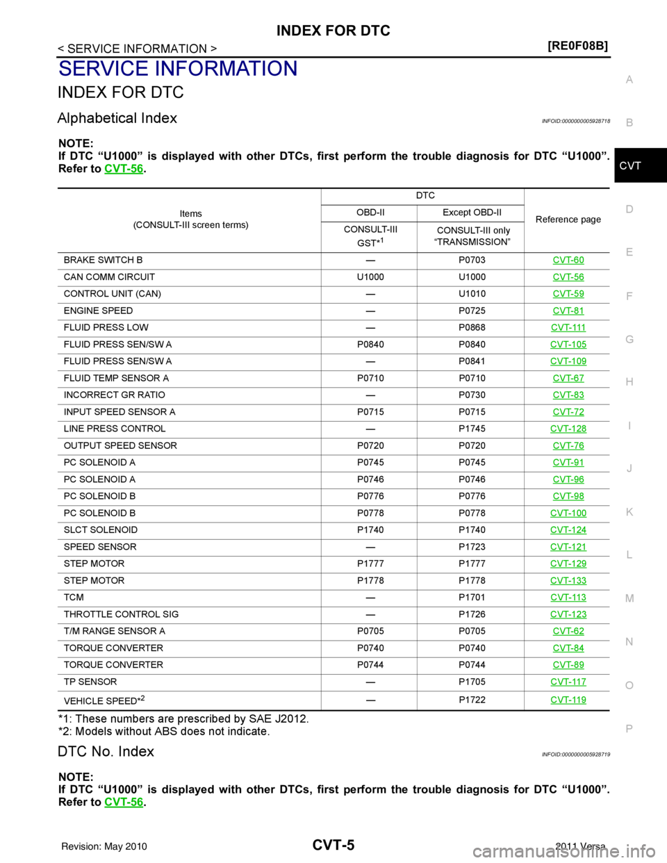
INDEX FOR DTC
Alphabetical IndexINFOID:0000000005928718
NOTE:
If DTC “U1000” is displayed with other DTCs, fi rst perform the trouble diagnosis for DTC “U1000”.
Refer to CVT-56
.
*1: These numbers are prescribed by SAE J2012.
*2: Models without ABS does not indicate.
DTC No. IndexINFOID:0000000005928719
NOTE:
If DTC “U1000” is displayed with other DTCs, fi rst perform the trouble diagnosis for DTC “U1000”.
Refer to CVT-56
.
Items
(CONSULT-III screen terms) DTC
Reference page
OBD-II
Except OBD-II
CONSULT-III GST*
1 CONSULT-III only
“TRANSMISSION”
BRAKE SWITCH B —P0703 CVT-60
CAN COMM CIRCUIT U1000 U1000 CVT-56
CONTROL UNIT (CAN)—U1010 CVT-59
ENGINE SPEED —P0725 CVT-81
FLUID PRESS LOW —P0868C V T- 111
FLUID PRESS SEN/SW A P0840P0840CVT-105
FLUID PRESS SEN/SW A —P0841CVT-109
FLUID TEMP SENSOR A P0710P0710CVT-67
INCORRECT GR RATIO —P0730 CVT-83
INPUT SPEED SENSOR A P0715P0715CVT-72
LINE PRESS CONTROL —P1745CVT-128
OUTPUT SPEED SENSOR P0720P0720CVT-76
PC SOLENOID A P0745P0745CVT-91
PC SOLENOID A P0746P0746CVT-96
PC SOLENOID B P0776P0776CVT-98
PC SOLENOID B P0778P0778CVT-100
SLCT SOLENOID P1740P1740CVT-124
SPEED SENSOR —P1723CVT-121
STEP MOTOR P1777P1777CVT-129
STEP MOTOR P1778P1778CVT-133
TCM —P1701CVT-113
THROTTLE CONTROL SIG —P1726CVT-123
T/M RANGE SENSOR A P0705P0705CVT-62
TORQUE CONVERTER P0740P0740CVT-84
TORQUE CONVERTER P0744 P0744 CVT-89
TP SENSOR —P1705CVT-117
VEHICLE SPEED*2— P1722CVT-119
Revision: May 2010 2011 Versa