sensor NISSAN LATIO 2011 Service Repair Manual
[x] Cancel search | Manufacturer: NISSAN, Model Year: 2011, Model line: LATIO, Model: NISSAN LATIO 2011Pages: 3787, PDF Size: 78.35 MB
Page 650 of 3787
BL-140
< SERVICE INFORMATION >
INTELLIGENT KEY SYSTEM
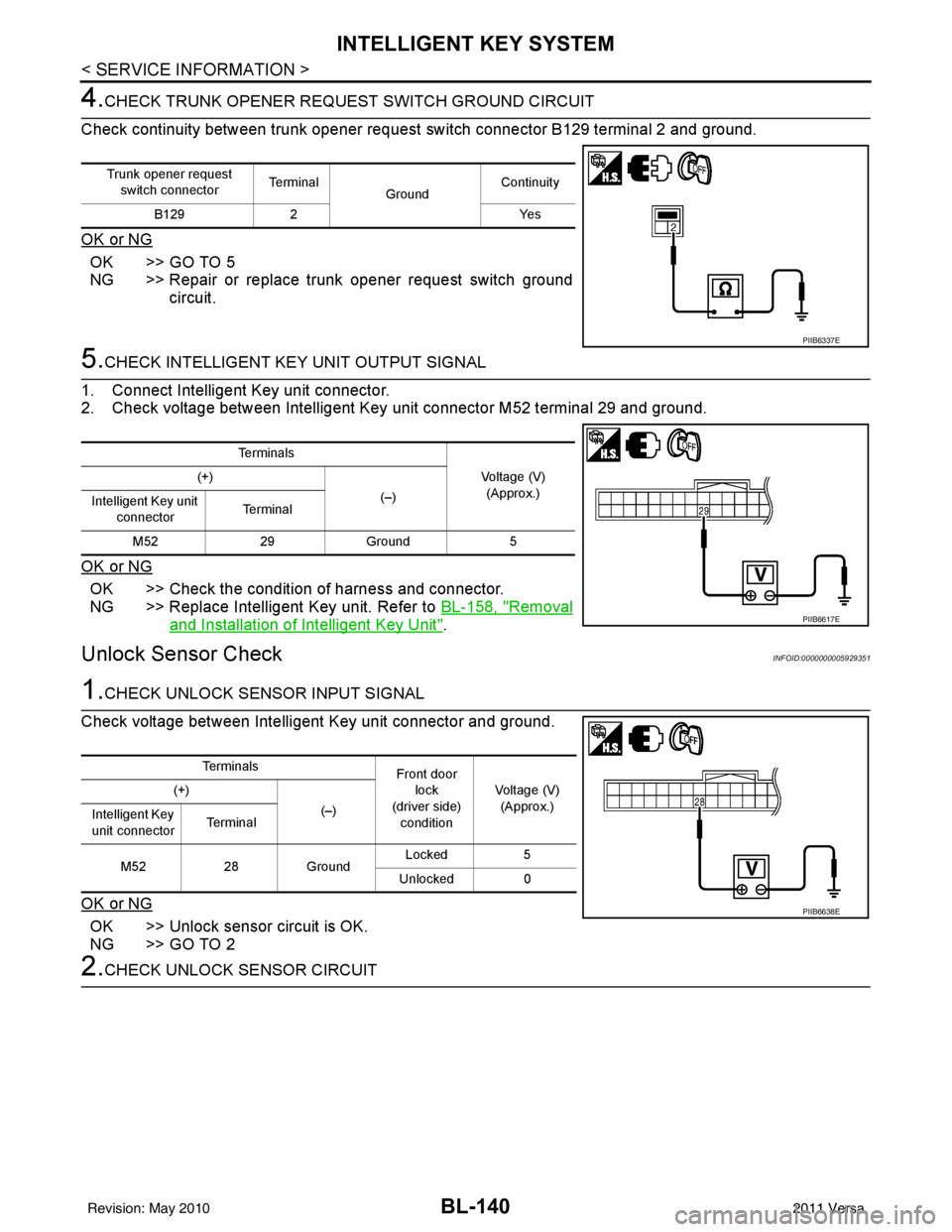
4.CHECK TRUNK OPENER REQUEST SWITCH GROUND CIRCUIT
Check continuity between trunk opener request switch connector B129 terminal 2 and ground.
OK or NG
OK >> GO TO 5
NG >> Repair or replace trunk opener request switch ground circuit.
5.CHECK INTELLIGENT KEY UNIT OUTPUT SIGNAL
1. Connect Intelligent Key unit connector.
2. Check voltage between Intelligent Key unit connector M52 terminal 29 and ground.
OK or NG
OK >> Check the condition of harness and connector.
NG >> Replace Intelligent Key unit. Refer to BL-158, "
Removal
and Installation of Intelligent Key Unit".
Unlock Sensor CheckINFOID:0000000005929351
1.CHECK UNLOCK SENSOR INPUT SIGNAL
Check voltage between Intelligent Key unit connector and ground.
OK or NG
OK >> Unlock sensor circuit is OK.
NG >> GO TO 2
2.CHECK UNLOCK SENSOR CIRCUIT
Trunk opener request switch connector Te r m i n a l
GroundContinuity
B129 2 Yes
PIIB6337E
Te r m i n a l s
Voltage (V)(Approx.)
(+)
(–)
Intelligent Key unit
connector Te r m i n a l
M52 29Ground 5
PIIB6617E
Te r m i n a l s
Front door
lock
(driver side) condition Voltage (V)
(Approx.)
(+)
(–)
Intelligent Key
unit connector Te r m i n a l
M52 28Ground Locked
5
Unlocked 0
PIIB6638E
Revision: May 2010 2011 Versa
Page 651 of 3787
INTELLIGENT KEY SYSTEMBL-141
< SERVICE INFORMATION >
C
DE
F
G H
J
K L
M A
B
BL
N
O P
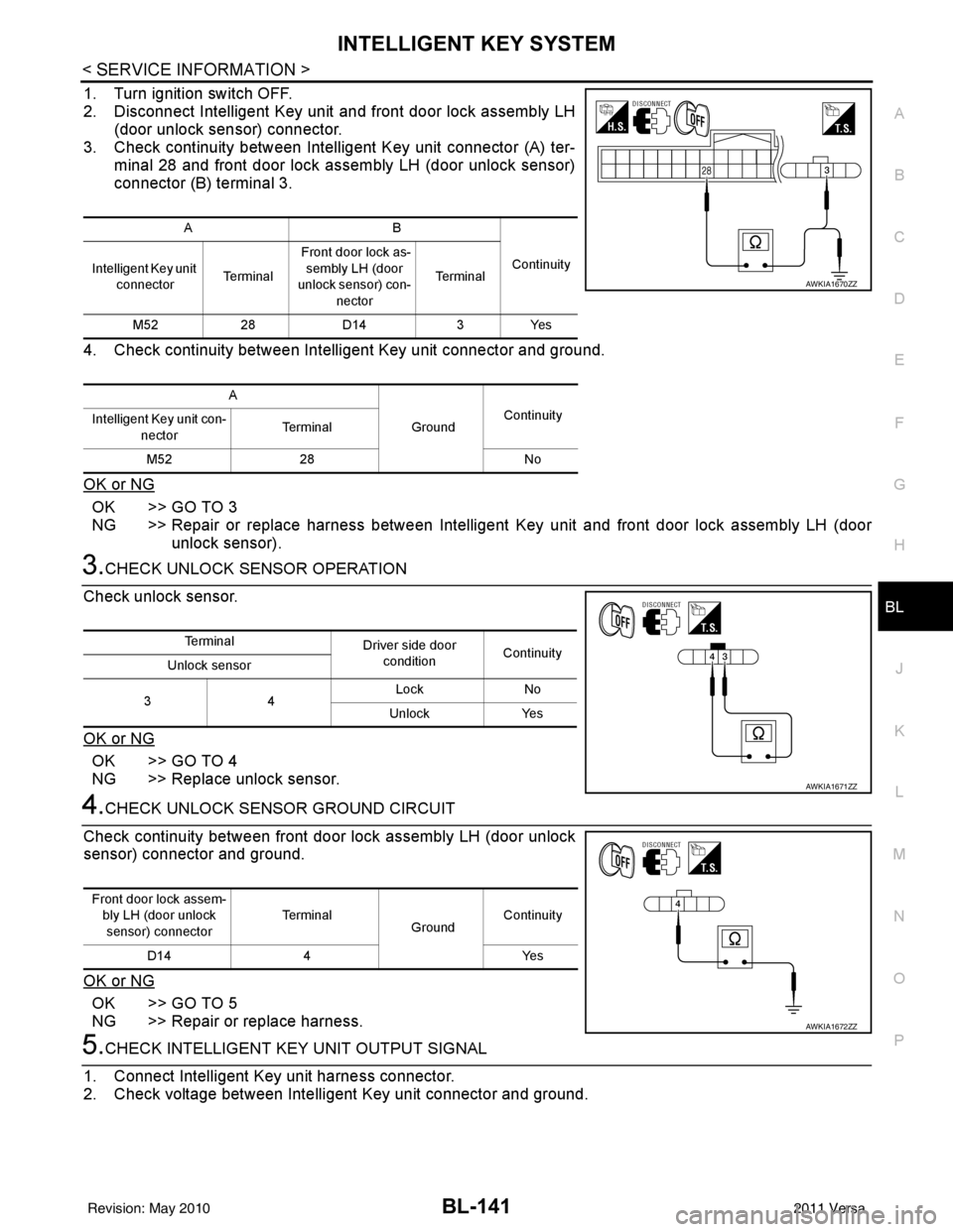
1. Turn ignition switch OFF.
2. Disconnect Intelligent Key unit and front door lock assembly LH (door unlock sensor) connector.
3. Check continuity between Intelligent Key unit connector (A) ter- minal 28 and front door lock assembly LH (door unlock sensor)
connector (B) terminal 3.
4. Check continuity between Intelligent Key unit connector and ground.
OK or NG
OK >> GO TO 3
NG >> Repair or replace harness between Intelligent Key unit and front door lock assembly LH (door unlock sensor).
3.CHECK UNLOCK SENSOR OPERATION
Check unlock sensor.
OK or NG
OK >> GO TO 4
NG >> Replace unlock sensor.
4.CHECK UNLOCK SENSOR GROUND CIRCUIT
Check continuity between front door lock assembly LH (door unlock
sensor) connector and ground.
OK or NG
OK >> GO TO 5
NG >> Repair or replace harness.
5.CHECK INTELLIGENT KEY UNIT OUTPUT SIGNAL
1. Connect Intelligent Key unit harness connector.
2. Check voltage between Intelligent Key unit connector and ground.
AB
Continuity
Intelligent Key unit
connector Te r m i n a l Front door lock as-
sembly LH (door
unlock sensor) con-
nector Te r m i n a l
M52 28D14 3Yes
A GroundContinuity
Intelligent Key unit con-
nector Te r m i n a l
M52 28 No
AWKIA1670ZZ
Te r m i n a l
Driver side door
condition Continuity
Unlock sensor
34 Lock
No
Unlock Yes
AWKIA1671ZZ
Front door lock assem-
bly LH (door unlock sensor) connector Te r m i n a l
GroundContinuity
D14 4 Yes
AWKIA1672ZZ
Revision: May 2010 2011 Versa
Page 683 of 3787
BACK DOOR LOCKBL-173
< SERVICE INFORMATION >
C
DE
F
G H
J
K L
M A
B
BL
N
O P
BACK DOOR LOCK
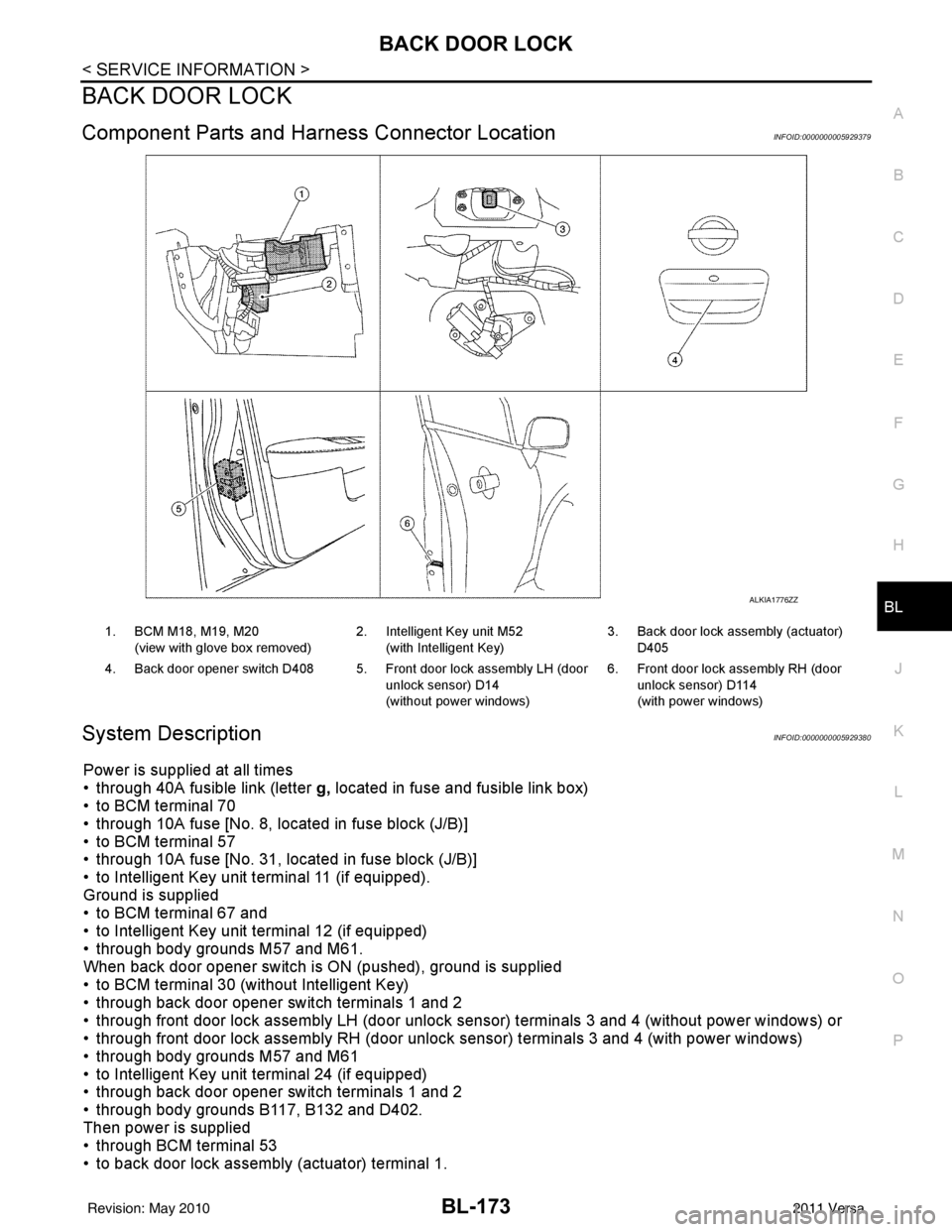
Component Parts and Har ness Connector LocationINFOID:0000000005929379
System DescriptionINFOID:0000000005929380
Power is supplied at all times
• through 40A fusible link (letter g, located in fuse and fusible link box)
• to BCM terminal 70
• through 10A fuse [No. 8, located in fuse block (J/B)]
• to BCM terminal 57
• through 10A fuse [No. 31, located in fuse block (J/B)]
• to Intelligent Key unit terminal 11 (if equipped).
Ground is supplied
• to BCM terminal 67 and
• to Intelligent Key unit terminal 12 (if equipped)
• through body grounds M57 and M61.
When back door opener switch is ON (pushed), ground is supplied
• to BCM terminal 30 (without Intelligent Key)
• through back door opener switch terminals 1 and 2
• through front door lock assembly LH (door unlock sensor) terminals 3 and 4 (without power windows) or
• through front door lock assembly RH (door unlock sensor) terminals 3 and 4 (with power windows)
• through body grounds M57 and M61
• to Intelligent Key unit terminal 24 (if equipped)
• through back door opener switch terminals 1 and 2
• through body grounds B117, B132 and D402.
Then power is supplied
• through BCM terminal 53
• to back door lock assembly (actuator) terminal 1.
ALKIA1776ZZ
1. BCM M18, M19, M20
(view with glove box removed) 2. Intelligent Key unit M52
(with Intelligent Key) 3. Back door lock assembly (actuator)
D405
4. Back door opener switch D408 5. Front door lock assembly LH (door unlock sensor) D14
(without power windows)6. Front door lock assembly RH (door
unlock sensor) D114
(with power windows)
Revision: May 2010 2011 Versa
Page 692 of 3787
BL-182
< SERVICE INFORMATION >
BACK DOOR LOCK
*1: With continuously variable transmission (CVT) or automatic transmission (A/T).
*2: With manual transmission (M/T).
CONSULT-III Function (BCM)INFOID:0000000005929384
CONSULT-III can display each diagnostic item us ing the diagnostic test modes shown following.
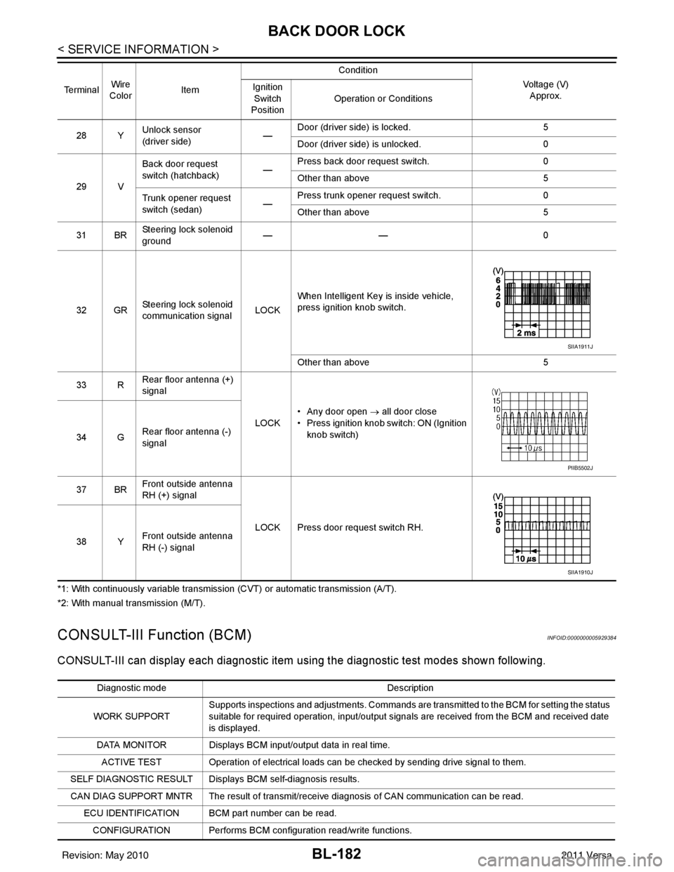
28 YUnlock sensor
(driver side) —Door (driver si
de) is locked. 5
Door (driver side ) is unlocked. 0
29 V Back door request
switch (hatchback)
—Press back door request switch.
0
Other than above 5
Trunk opener request
switch (sedan) —Press trunk opener request switch.
0
Other than above 5
31 BR Steering lock solenoid
ground ——
0
32 GR Steering lock solenoid
communication signal LOCKWhen Intelligent Key is inside vehicle,
press ignition knob switch.
Other than above
5
33 R Rear floor antenna (+)
signal
LOCK• Any door open
→ all door close
• Press ignition knob switch: ON (Ignition
knob switch)
34 G Rear floor antenna (-)
signal
37 BR Front outside antenna
RH (+) signal
LOCK Press door request switch RH.
38 Y Front outside antenna
RH (-) signal
Te r m i n a l
Wire
Color Item Condition
Voltage (V)Approx.
Ignition
Switch
Position Operation or Conditions
SIIA1911J
PIIB5502J
SIIA1910J
Diagnostic mode
Description
WORK SUPPORT Supports inspections and adjustments. Commands are transmitted to the BCM for setting the status
suitable for required operation, input/output signals are received from the BCM and received date
is displayed.
DATA MONITOR Displays BCM input/output data in real time. ACTIVE TEST Operation of electrical loads can be checked by sending drive signal to them.
SELF DIAGNOSTIC RESULT Displays BCM self-diagnosis results.
CAN DIAG SUPPORT MNTR The result of transmit/receive diagnosis of CAN communication can be read. ECU IDENTIFICATION BCM part number can be read.CONFIGURATION Performs BCM configuration read/write functions.
Revision: May 2010 2011 Versa
Page 696 of 3787
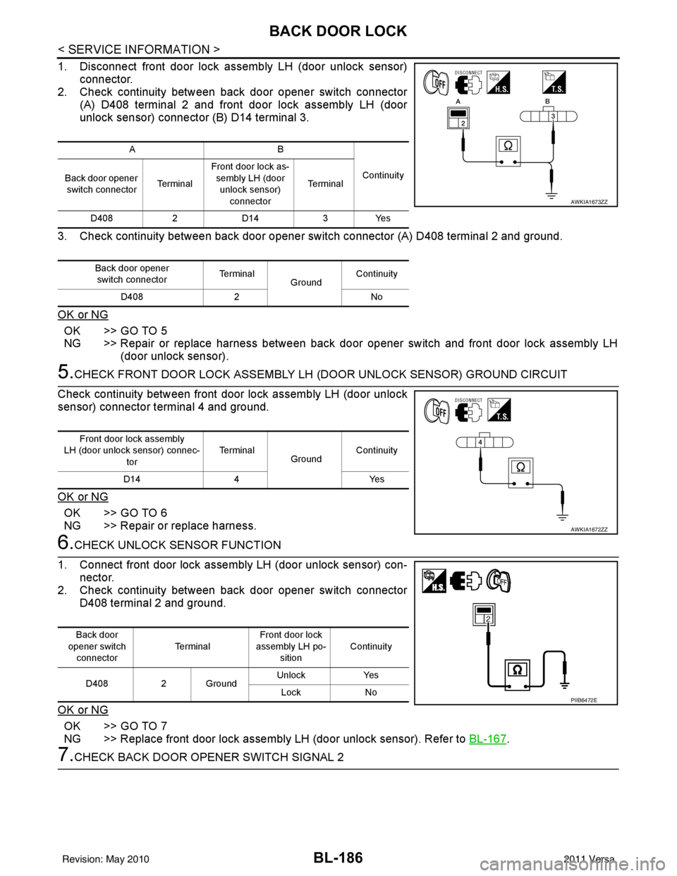
BL-186
< SERVICE INFORMATION >
BACK DOOR LOCK
1. Disconnect front door lock assembly LH (door unlock sensor)connector.
2. Check continuity between back door opener switch connector
(A) D408 terminal 2 and front door lock assembly LH (door
unlock sensor) connector (B) D14 terminal 3.
3. Check continuity between back door opener switch connector (A) D408 terminal 2 and ground.
OK or NG
OK >> GO TO 5
NG >> Repair or replace harness between back door opener switch and front door lock assembly LH
(door unlock sensor).
5.CHECK FRONT DOOR LOCK ASSEMBLY LH (DOOR UNLOCK SENSOR) GROUND CIRCUIT
Check continuity between front door lock assembly LH (door unlock
sensor) connector terminal 4 and ground.
OK or NG
OK >> GO TO 6
NG >> Repair or replace harness.
6.CHECK UNLOCK SENSOR FUNCTION
1. Connect front door lock assembly LH (door unlock sensor) con- nector.
2. Check continuity between back door opener switch connector
D408 terminal 2 and ground.
OK or NG
OK >> GO TO 7
NG >> Replace front door lock assembly LH (door unlock sensor). Refer to BL-167
.
7.CHECK BACK DOOR OPENER SWITCH SIGNAL 2
AB
Continuity
Back door opener
switch connector Te r m i n a lFront door lock as-
sembly LH (door unlock sensor) connector Te r m i n a l
D408 2D14 3Yes
Back door opener switch connector Te r m i n a l
GroundContinuity
D408 2 No
AWKIA1673ZZ
Front door lock assembly
LH (door unlock sensor) connec- tor Te r m i n a l
GroundContinuity
D14 4 Yes
AWKIA1672ZZ
Back door
opener switch
connector Te r m i n a l
Front door lock
assembly LH po-
sition Continuity
D408 2 Ground Unlock
Yes
Lock No
PIIB6472E
Revision: May 2010 2011 Versa
Page 698 of 3787
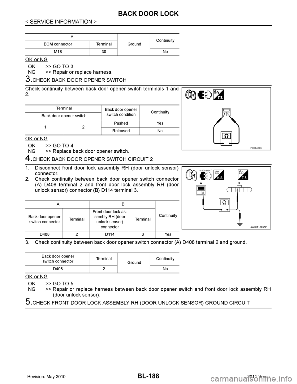
BL-188
< SERVICE INFORMATION >
BACK DOOR LOCK
OK or NG
OK >> GO TO 3
NG >> Repair or replace harness.
3.CHECK BACK DOOR OPENER SWITCH
Check continuity between back door opener switch terminals 1 and
2.
OK or NG
OK >> GO TO 4
NG >> Replace back door opener switch.
4.CHECK BACK DOOR OPENER SWITCH CIRCUIT 2
1. Disconnect front door lock assembly RH (door unlock sensor) connector.
2. Check continuity between back door opener switch connector (A) D408 terminal 2 and front door lock assembly RH (door
unlock sensor) connector (B) D114 terminal 3.
3. Check continuity between back door opener switch connector (A) D408 terminal 2 and ground.
OK or NG
OK >> GO TO 5
NG >> Repair or replace harness between back door opener switch and front door lock assembly RH (door unlock sensor).
5.CHECK FRONT DOOR LOCK ASSEMBLY RH (DOOR UNLOCK SENSOR) GROUND CIRCUIT
A
GroundContinuity
BCM connector Terminal
M18 30 No
Te r m i n a l
Back door opener
switch condition Continuity
Back door opener switch
12 Pushed Yes
Released No
PIIB6470E
AB
Continuity
Back door opener
switch connector Te r m i n a lFront door lock as-
sembly RH (door
unlock sensor) connector Te r m i n a l
D408 2D114 3Yes
Back door opener switch connector Te r m i n a l
GroundContinuity
D408 2 No
AWKIA1675ZZ
Revision: May 2010 2011 Versa
Page 699 of 3787
BACK DOOR LOCKBL-189
< SERVICE INFORMATION >
C
DE
F
G H
J
K L
M A
B
BL
N
O P
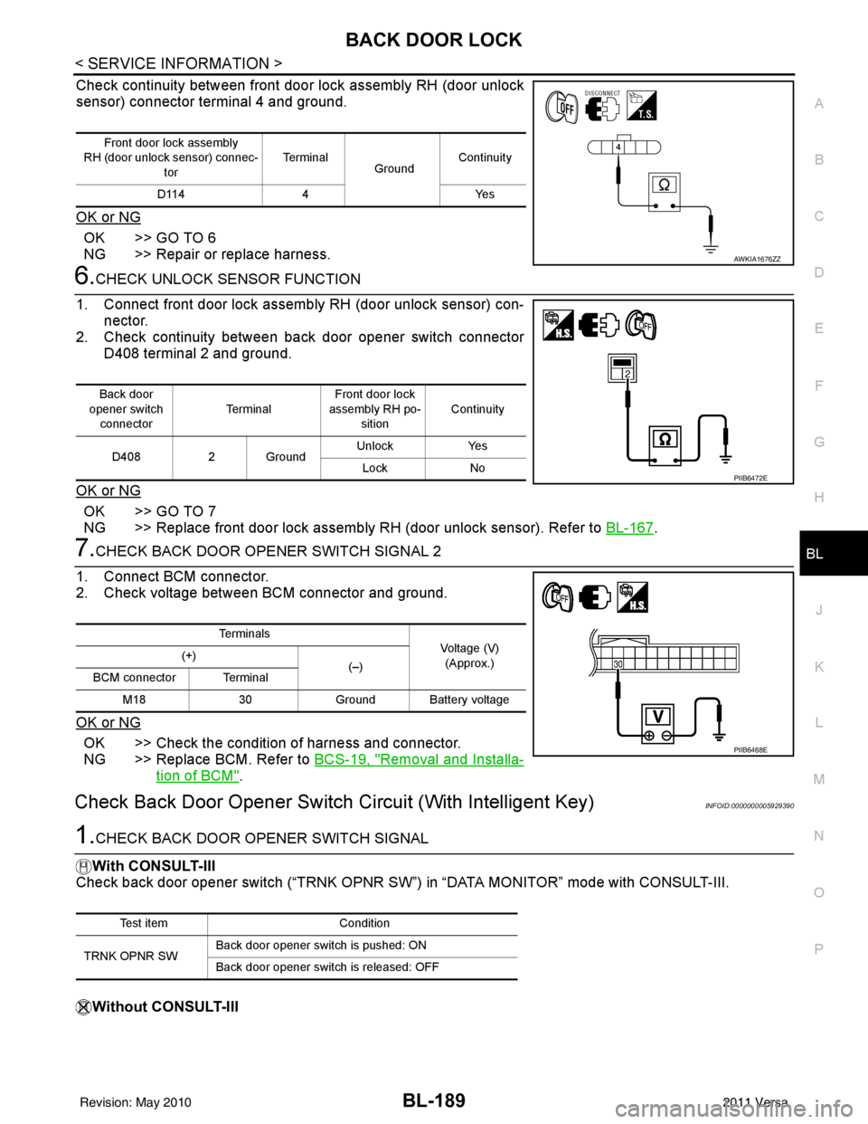
Check continuity between front door lock assembly RH (door unlock
sensor) connector terminal 4 and ground.
OK or NG
OK >> GO TO 6
NG >> Repair or replace harness.
6.CHECK UNLOCK SENSOR FUNCTION
1. Connect front door lock assembly RH (door unlock sensor) con- nector.
2. Check continuity between back door opener switch connector
D408 terminal 2 and ground.
OK or NG
OK >> GO TO 7
NG >> Replace front door lock assembly RH (door unlock sensor). Refer to BL-167
.
7.CHECK BACK DOOR OPENER SWITCH SIGNAL 2
1. Connect BCM connector.
2. Check voltage between BCM connector and ground.
OK or NG
OK >> Check the condition of harness and connector.
NG >> Replace BCM. Refer to BCS-19, "
Removal and Installa-
tion of BCM".
Check Back Door Opener Switch Circuit (With Intelligent Key)INFOID:0000000005929390
1.CHECK BACK DOOR OPENER SWITCH SIGNAL
With CONSULT-III
Check back door opener switch (“TRNK OPNR SW”) in “DATA MONITOR” mode with CONSULT-III.
Without CONSULT-III
Front door lock assembly
RH (door unlock sensor) connec- tor Te r m i n a l
GroundContinuity
D114 4 Yes
AWKIA1676ZZ
Back door
opener switch connector Te r m i n a lFront door lock
assembly RH po- sition Continuity
D408 2 Ground Unlock
Yes
Lock No
PIIB6472E
Te r m i n a l s
Voltage (V)
(Approx.)
(+)
(–)
BCM connector Terminal
M18 30Ground Battery voltage
PIIB6468E
Test item Condition
TRNK OPNR SW Back door opener switch is pushed: ON
Back door opener switch is released: OFF
Revision: May 2010
2011 Versa
Page 708 of 3787
BL-198
< SERVICE INFORMATION >
TRUNK LID OPENER
TRUNK LID OPENER
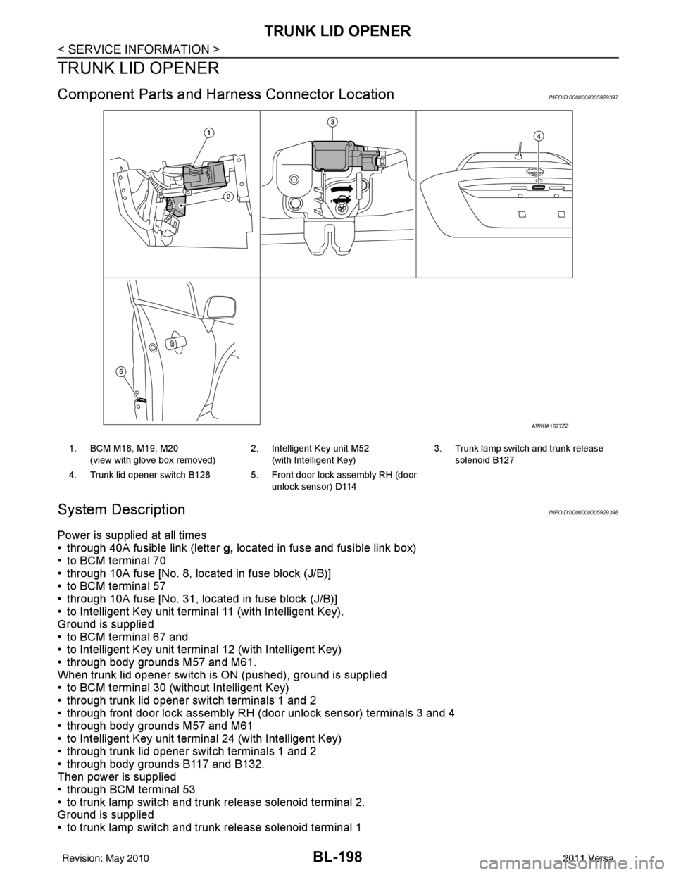
Component Parts and Harness Connector LocationINFOID:0000000005929397
System DescriptionINFOID:0000000005929398
Power is supplied at all times
• through 40A fusible link (letter g, located in fuse and fusible link box)
• to BCM terminal 70
• through 10A fuse [No. 8, located in fuse block (J/B)]
• to BCM terminal 57
• through 10A fuse [No. 31, located in fuse block (J/B)]
• to Intelligent Key unit terminal 11 (with Intelligent Key).
Ground is supplied
• to BCM terminal 67 and
• to Intelligent Key unit terminal 12 (with Intelligent Key)
• through body grounds M57 and M61.
When trunk lid opener switch is ON (pushed), ground is supplied
• to BCM terminal 30 (without Intelligent Key)
• through trunk lid opener switch terminals 1 and 2
• through front door lock assembly RH (door unlock sensor) terminals 3 and 4
• through body grounds M57 and M61
• to Intelligent Key unit terminal 24 (with Intelligent Key)
• through trunk lid opener switch terminals 1 and 2
• through body grounds B117 and B132.
Then power is supplied
• through BCM terminal 53
• to trunk lamp switch and trunk release solenoid terminal 2.
Ground is supplied
• to trunk lamp switch and trunk release solenoid terminal 1
AWKIA1677ZZ
1. BCM M18, M19, M20
(view with glove box removed) 2. Intelligent Key unit M52
(with Intelligent Key) 3. Trunk lamp switch and trunk release
solenoid B127
4. Trunk lid opener switch B128 5. Front door lock assembly RH (door unlock sensor) D114
Revision: May 2010 2011 Versa
Page 717 of 3787
TRUNK LID OPENERBL-207
< SERVICE INFORMATION >
C
DE
F
G H
J
K L
M A
B
BL
N
O P
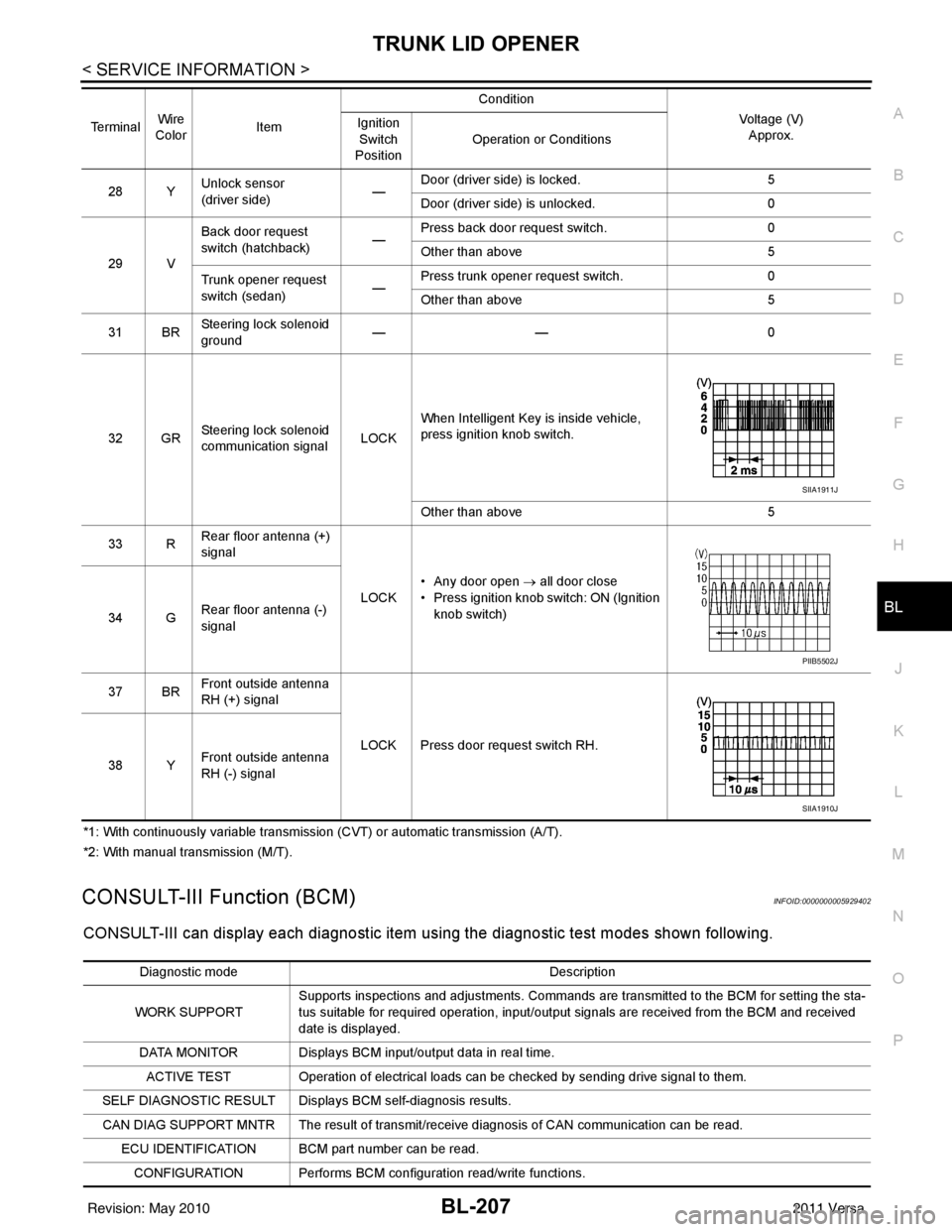
*1: With continuously variable transmission (CVT) or automatic transmission (A/T).
*2: With manual transmission (M/T).
CONSULT-III Function (BCM)INFOID:0000000005929402
CONSULT-III can display each diagnostic item using the diagnostic test modes shown following.
28 Y Unlock sensor
(driver side) —Door (driver si
de) is locked. 5
Door (driver side ) is unlocked. 0
29 V Back door request
switch (hatchback)
—Press back door request switch.
0
Other than above 5
Trunk opener request
switch (sedan) —Press trunk opener request switch.
0
Other than above 5
31 BR Steering lock solenoid
ground ——
0
32 GR Steering lock solenoid
communication signal LOCKWhen Intelligent Key is inside vehicle,
press ignition knob switch.
Other than above
5
33 R Rear floor antenna (+)
signal
LOCK• Any door open
→ all door close
• Press ignition knob switch: ON (Ignition
knob switch)
34 G Rear floor antenna (-)
signal
37 BR Front outside antenna
RH (+) signal
LOCK Press door request switch RH.
38 Y Front outside antenna
RH (-) signal
Terminal
Wire
Color Item Condition
Voltage (V)Approx.
Ignition
Switch
Position Operation or Conditions
SIIA1911J
PIIB5502J
SIIA1910J
Diagnostic mode
Description
WORK SUPPORT Supports inspections and adjustments. Commands are transmitted to the BCM for setting the sta-
tus suitable for required operation, input/output signals are received from the BCM and received
date is displayed.
DATA MONITOR Displays BCM input/output data in real time. ACTIVE TEST Operation of electrical loads can be checked by sending drive signal to them.
SELF DIAGNOSTIC RESULT Displays BCM self-diagnosis results.
CAN DIAG SUPPORT MNTR The result of transmit/receive diagnosis of CAN communication can be read. ECU IDENTIFICATION BCM part number can be read.CONFIGURATION Performs BCM configuration read/write functions.
Revision: May 2010 2011 Versa
Page 721 of 3787
TRUNK LID OPENERBL-211
< SERVICE INFORMATION >
C
DE
F
G H
J
K L
M A
B
BL
N
O P
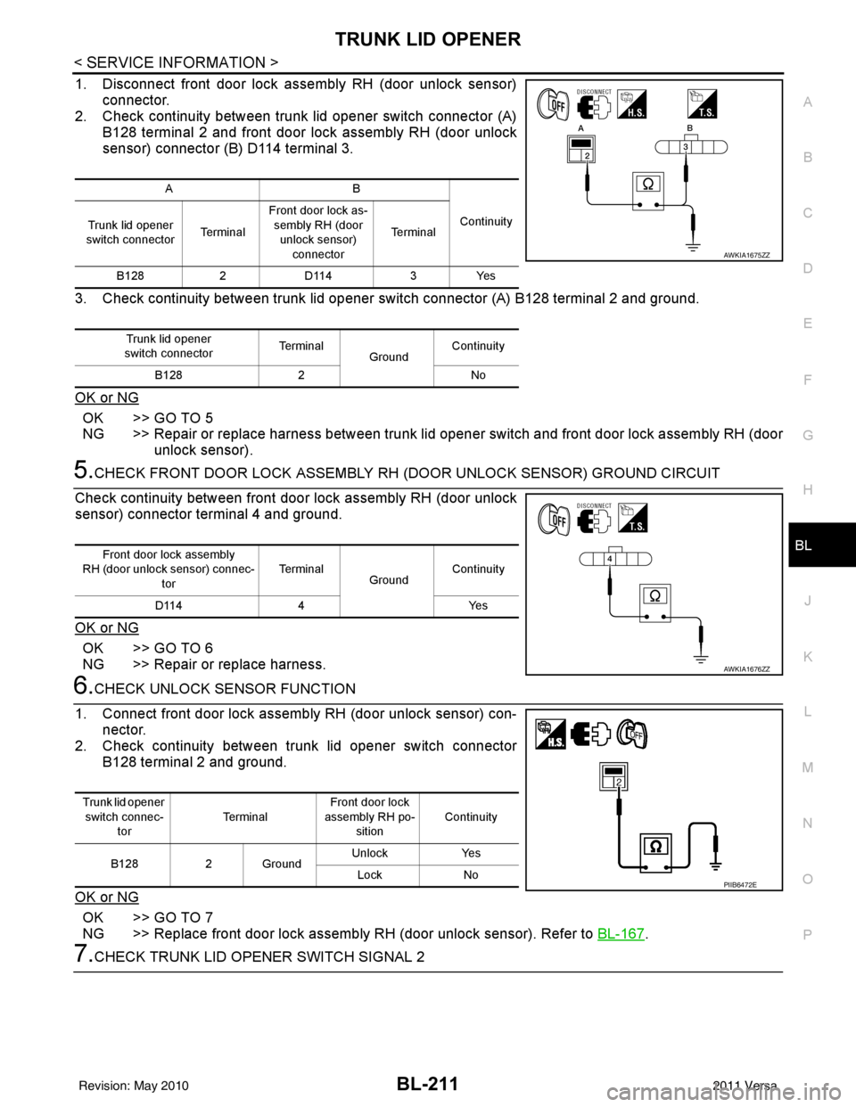
1. Disconnect front door lock asse mbly RH (door unlock sensor)
connector.
2. Check continuity between trunk lid opener switch connector (A)
B128 terminal 2 and front door lock assembly RH (door unlock
sensor) connector (B) D114 terminal 3.
3. Check continuity between trunk lid opener switch connector (A) B128 terminal 2 and ground.
OK or NG
OK >> GO TO 5
NG >> Repair or replace harness between trunk lid opener switch and front door lock assembly RH (door unlock sensor).
5.CHECK FRONT DOOR LOCK ASSEMBLY RH (DOOR UNLOCK SENSOR) GROUND CIRCUIT
Check continuity between front door lock assembly RH (door unlock
sensor) connector terminal 4 and ground.
OK or NG
OK >> GO TO 6
NG >> Repair or replace harness.
6.CHECK UNLOCK SENSOR FUNCTION
1. Connect front door lock assembly RH (door unlock sensor) con- nector.
2. Check continuity between trunk lid opener switch connector
B128 terminal 2 and ground.
OK or NG
OK >> GO TO 7
NG >> Replace front door lock assembly RH (door unlock sensor). Refer to BL-167
.
7.CHECK TRUNK LID OPENER SWITCH SIGNAL 2
AB
Continuity
Trunk lid opener
switch connector Te r m i n a lFront door lock as-
sembly RH (door unlock sensor) connector Te r m i n a l
B128 2D114 3Yes
Trunk lid opener
switch connector Te r m i n a l
GroundContinuity
B128 2 No
AWKIA1675ZZ
Front door lock assembly
RH (door unlock sensor) connec- tor Te r m i n a l
GroundContinuity
D114 4 Yes
AWKIA1676ZZ
Trunk lid opener
switch connec-
tor Te r m i n a l
Front door lock
assembly RH po-
sition Continuity
B128 2 Ground Unlock
Yes
Lock No
PIIB6472E
Revision: May 2010 2011 Versa