fuse NISSAN LATIO 2011 Service Owner's Manual
[x] Cancel search | Manufacturer: NISSAN, Model Year: 2011, Model line: LATIO, Model: NISSAN LATIO 2011Pages: 3787, PDF Size: 78.35 MB
Page 559 of 3787
POWER DOOR LOCK SYSTEMBL-49
< SERVICE INFORMATION >
C
DE
F
G H
J
K L
M A
B
BL
N
O P
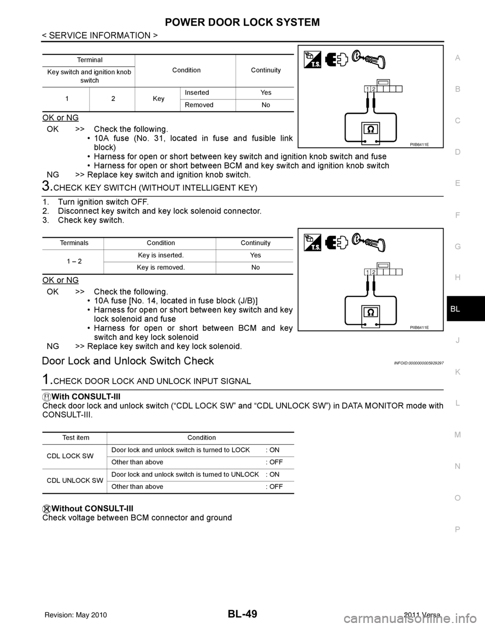
OK or NG
OK >> Check the following. • 10A fuse (No. 31, located in fuse and fusible linkblock)
• Harness for open or short between key switch and ignition knob switch and fuse
• Harness for open or short between BCM and key switch and ignition knob switch
NG >> Replace key switch and ignition knob switch.
3.CHECK KEY SWITCH (WITHO UT INTELLIGENT KEY)
1. Turn ignition switch OFF.
2. Disconnect key switch and key lock solenoid connector.
3. Check key switch.
OK or NG
OK >> Check the following. • 10A fuse [No. 14, located in fuse block (J/B)]
• Harness for open or short between key switch and key
lock solenoid and fuse
• Harness for open or short between BCM and key
switch and key lock solenoid
NG >> Replace key switch and key lock solenoid.
Door Lock and Unlock Switch CheckINFOID:0000000005929297
1.CHECK DOOR LOCK AND UNLOCK INPUT SIGNAL
With CONSULT-III
Check door lock and unlock switch (“CDL LOCK SW” and “CDL UNLOCK SW”) in DATA MONITOR mode with
CONSULT-III.
Without CONSULT-III
Check voltage between BCM connector and ground
Te r m i n a l
ConditionContinuity
Key switch and ignition knob
switch
12K ey Inserted
Yes
Removed No
PIIB6411E
Terminals Condition Continuity
1 – 2 Key is inserted.
Yes
Key is removed. No
PIIB6411E
Test item Condition
CDL LOCK SW Door lock and unlock switch is turned to LOCK : ON
Other than above
: OFF
CDL UNLOCK SW Door lock and unlock switch is turned to UNLOCK : ON
Other than above
: OFF
Revision: May 2010 2011 Versa
Page 568 of 3787
BL-58
< SERVICE INFORMATION >
REMOTE KEYLESS ENTRY SYSTEM
REMOTE KEYLESS ENTRY SYSTEM
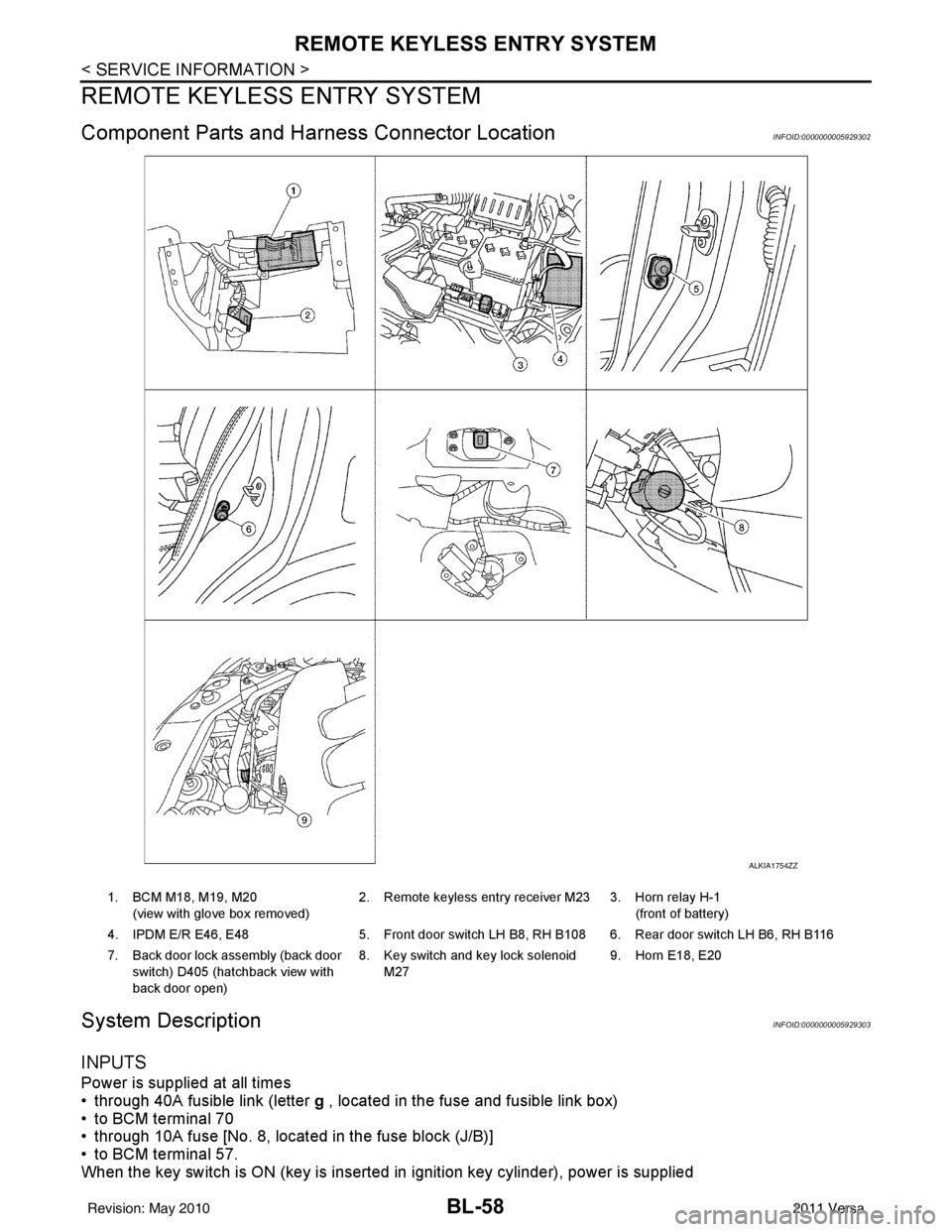
Component Parts and Harness Connector LocationINFOID:0000000005929302
System DescriptionINFOID:0000000005929303
INPUTS
Power is supplied at all times
• through 40A fusible link (letter g , located in the fuse and fusible link box)
• to BCM terminal 70
• through 10A fuse [No. 8, located in the fuse block (J/B)]
• to BCM terminal 57.
When the key switch is ON (key is inserted in ignition key cylinder), power is supplied
ALKIA1754ZZ
1. BCM M18, M19, M20
(view with glove box removed) 2. Remote keyless entry receiver M23 3. Horn relay H-1
(front of battery)
4. IPDM E/R E46, E48 5. Front door switch LH B8, RH B108 6. Rear door switch LH B6, RH B116
7. Back door lock assembly (back door switch) D405 (hatchback view with
back door open) 8. Key switch and key lock solenoid
M27 9. Horn E18, E20
Revision: May 2010
2011 Versa
Page 569 of 3787
![NISSAN LATIO 2011 Service Owners Manual REMOTE KEYLESS ENTRY SYSTEMBL-59
< SERVICE INFORMATION >
C
DE
F
G H
J
K L
M A
B
BL
N
O P
• through 10A fuse [No. 14, located in the fuse block (J/B)]
• through key switch terminals 2 and 1
• to NISSAN LATIO 2011 Service Owners Manual REMOTE KEYLESS ENTRY SYSTEMBL-59
< SERVICE INFORMATION >
C
DE
F
G H
J
K L
M A
B
BL
N
O P
• through 10A fuse [No. 14, located in the fuse block (J/B)]
• through key switch terminals 2 and 1
• to](/img/5/57357/w960_57357-568.png)
REMOTE KEYLESS ENTRY SYSTEMBL-59
< SERVICE INFORMATION >
C
DE
F
G H
J
K L
M A
B
BL
N
O P
• through 10A fuse [No. 14, located in the fuse block (J/B)]
• through key switch terminals 2 and 1
• to BCM terminal 37.
When the ignition switch is ACC or ON, power is supplied
• through 10A fuse [No. 20, located in the fuse block (J/B)]
• to BCM terminal 11.
Ground is supplied
• to BCM terminal 67
• through body grounds M57 and M61.
When the front door switch LH is ON (door is OPEN), ground is supplied
• to BCM terminal 47
• through front door switch LH terminal 2
• through front door switch LH case ground.
When the front door switch RH is ON (door is OPEN), ground is supplied
• to BCM terminal 12
• through front door switch RH terminal 2
• through front door switch RH case ground.
When the rear door switch LH is ON (door is OPEN), ground is supplied
• to BCM terminal 48
• through rear door switch LH terminal 1
• through rear door switch LH case ground.
When the rear door switch RH is ON (door is OPEN), ground is supplied
• to BCM meter terminal 13
• through rear door switch RH terminal 1
• through rear door switch RH case ground.
When the back door lock assembly (back door switch) (hat chback) is ON (back door is OPEN), ground is sup-
plied
• to BCM terminal 43
• through back door lock assembly (back door switch) terminals 3 and 4
• through body grounds B117, B132 and D402.
Keyfob signal is inputted to BCM from remote keyless entry receiver.
The remote keyless entry system controls operation of the
• power door lock
• hazard reminder
• auto door lock
• panic alarm
• room lamp
OPERATED PROCEDURE
Power Door Lock Operation
BCM receives a LOCK signal from keyfob. BCM locks all doors with input of LOCK signal from keyfob.
BCM receives a UNLOCK signal from keyfob. BCM unlocks all doors with input of UNLOCK signal from key-
fob.
Hazard and Horn Reminder
When the doors are locked or unlocked by keyfob, power is supplied to sound horn and flash hazard warning
lamps as follows
• LOCK operation: 3 or 4 mode (lamps flash twice)
• UNLOCK operation: 2 or 4 mode (lamps flash once)
• Horn sounds once with LOCK function when this feature is set ON.
The hazard reminder has modes 1, 2, 3 or 4. The hor n reminder can be turned ON/OFF with any LOCK mode.
Operating function of hazard reminder
Hazard and horn reminders do not operate if any door switch is ON (any door is OPEN).
How to change hazard and horn reminder modes
Mode 1Mode 2Mode 3 Mode 4
Keyfob operation Lock Unlock Lock Unlock Lock Unlock Lock Unlock
Hazard warning lamp
flash — — — Twice Once — Once Twice
Horn sound (ON/OFF) ON: once — O N: once — ON: once — ON: once —
Revision: May 2010 2011 Versa
Page 584 of 3787
BL-74
< SERVICE INFORMATION >
REMOTE KEYLESS ENTRY SYSTEM
ACC Switch Circuit Check
INFOID:0000000005929314
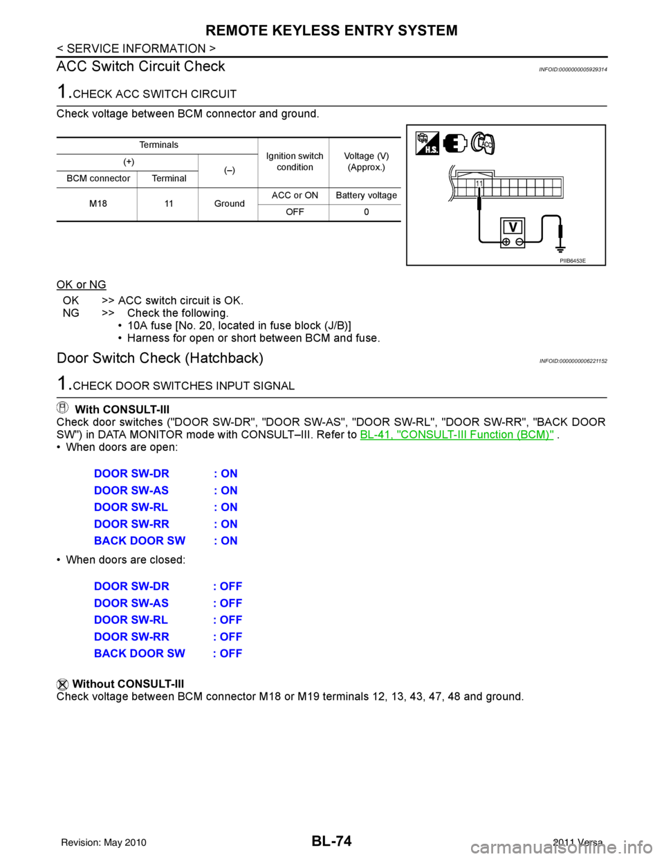
1.CHECK ACC SWITCH CIRCUIT
Check voltage between BCM connector and ground.
OK or NG
OK >> ACC switch circuit is OK.
NG >> Check the following. • 10A fuse [No. 20, located in fuse block (J/B)]
• Harness for open or short between BCM and fuse.
Door Switch Check (Hatchback)INFOID:0000000006221152
1.CHECK DOOR SWITCHES INPUT SIGNAL
With CONSULT-III
Check door switches ("DOOR SW-DR", "DOOR SW-AS", "DOOR SW-RL", "DOOR SW-RR", "BACK DOOR
SW") in DATA MONITOR mode with CONSULT–III. Refer to BL-41, "
CONSULT-III Function (BCM)" .
• When doors are open:
• When doors are closed:
Without CONSULT-III
Check voltage between BCM connector M18 or M19 terminals 12, 13, 43, 47, 48 and ground.
Te r m i n a l s
Ignition switch
condition Voltage (V)
(Approx.)
(+)
(–)
BCM connector Terminal
M18 11 Ground ACC or ON Battery voltage
OFF 0
PIIB6453E
DOOR SW-DR : ON
DOOR SW-AS : ON
DOOR SW-RL : ON
DOOR SW-RR : ON
BACK DOOR SW : ON
DOOR SW-DR : OFF
DOOR SW-AS : OFF
DOOR SW-RL : OFF
DOOR SW-RR : OFF
BACK DOOR SW : OFF
Revision: May 2010 2011 Versa
Page 588 of 3787
BL-78
< SERVICE INFORMATION >
REMOTE KEYLESS ENTRY SYSTEM
Key Switch (I nsert) Check
INFOID:0000000006221154
1.CHECK KEY SWITCH INPUT SIGNAL
With CONSULT-III
Check key switch "KEY ON SW" in DATA MONITOR mode with CONSULT–III. Refer to BL-41, "
CONSULT-III
Function (BCM)" .
• When key is inserted into ignition key cylinder:
• When key is removed from ignition key cylinder:
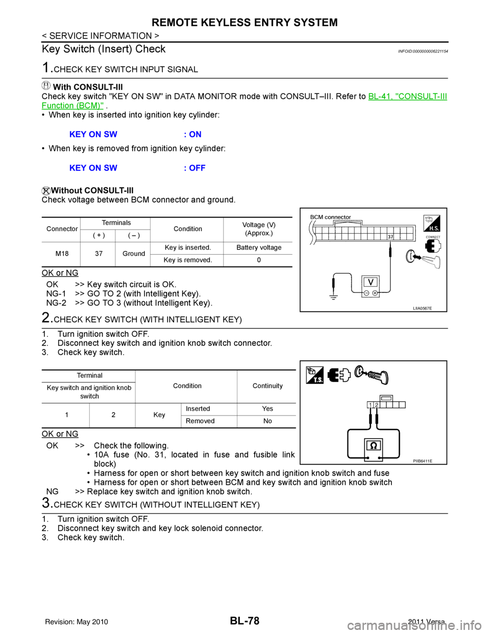
Without CONSULT-III
Check voltage between BCM connector and ground.
OK or NG
OK >> Key switch circuit is OK.
NG-1 >> GO TO 2 (with Intelligent Key).
NG-2 >> GO TO 3 (without Intelligent Key).
2.CHECK KEY SWITCH (WITH INTELLIGENT KEY)
1. Turn ignition switch OFF.
2. Disconnect key switch and ignition knob switch connector.
3. Check key switch.
OK or NG
OK >> Check the following. • 10A fuse (No. 31, located in fuse and fusible link
block)
• Harness for open or short between key switch and ignition knob switch and fuse
• Harness for open or short between BCM and key switch and ignition knob switch
NG >> Replace key switch and ignition knob switch.
3.CHECK KEY SWITCH (WITHO UT INTELLIGENT KEY)
1. Turn ignition switch OFF.
2. Disconnect key switch and key lock solenoid connector.
3. Check key switch. KEY ON SW
: ON
KEY ON SW : OFF
ConnectorTe r m i n a l s
ConditionVoltage (V)
(Approx.)
( + ) ( – )
M18 37 Ground Key is inserted. Battery voltage
Key is removed. 0
LIIA0567E
Te r m i n a l
Condition Continuity
Key switch and ignition knob
switch
12K ey Inserted
Yes
Removed No
PIIB6411E
Revision: May 2010 2011 Versa
Page 589 of 3787
![NISSAN LATIO 2011 Service Owners Manual REMOTE KEYLESS ENTRY SYSTEMBL-79
< SERVICE INFORMATION >
C
DE
F
G H
J
K L
M A
B
BL
N
O P
OK or NG
OK >> Check the following. • 10A fuse [No. 14, located in fuse block (J/B)]
• Harness for open or NISSAN LATIO 2011 Service Owners Manual REMOTE KEYLESS ENTRY SYSTEMBL-79
< SERVICE INFORMATION >
C
DE
F
G H
J
K L
M A
B
BL
N
O P
OK or NG
OK >> Check the following. • 10A fuse [No. 14, located in fuse block (J/B)]
• Harness for open or](/img/5/57357/w960_57357-588.png)
REMOTE KEYLESS ENTRY SYSTEMBL-79
< SERVICE INFORMATION >
C
DE
F
G H
J
K L
M A
B
BL
N
O P
OK or NG
OK >> Check the following. • 10A fuse [No. 14, located in fuse block (J/B)]
• Harness for open or short between key switch and keylock solenoid and fuse
• Harness for open or short between BCM and key
switch and key lock solenoid
NG >> Replace key switch and key lock solenoid.
Hazard Function CheckINFOID:0000000005929318
1.CHECK HAZARD WARNING LAMP
Does hazard warning lamp flash with hazard switch?
OK or NG
OK >> Hazard warning lamp circuit is OK.
NG >> Check hazard circuit. Refer to LT- 5 0
.
Horn Function CheckINFOID:0000000005929319
First perform the “SELF-DIAG RESULTS” in “BCM” with CONSULT-III, then perform the trouble diagnosis of
malfunction system indicated “SELF-DIAG RESULTS” of “BCM”. Refer to BCS-18, "
CAN Communication
Inspection Using CONSULT-III (Self-Diagnosis)" .
1.CHECK HORN FUNCTION
Does horn sound with horn switch?
OK or NG
OK >> GO TO 2
NG >> Check horn circuit. Refer to WW-40
.
2.CHECK IPDM E/R INPUT SIGNAL
Check voltage between IPDM E/R connector and ground.
OK or NG
OK >> Replace IPDM E/R. Refer to PG-28, "Removal and
Installation of IPDM E/R".
NG >> GO TO 3
3.CHECK HORN RELAY CIRCUIT
1. Turn ignition switch OFF.
2. Disconnect IPDM E/R and horn relay connector.
Terminals Condition Continuity
1 – 2 Key is inserted.
Yes
Key is removed. No
PIIB6411E
Te r m i n a l s
Voltage (V)
(Approx.)
(+)
(–)
IPDM E/R connector Terminal
E46 45Ground Battery voltage
WIIA1251E
Revision: May 2010 2011 Versa
Page 618 of 3787
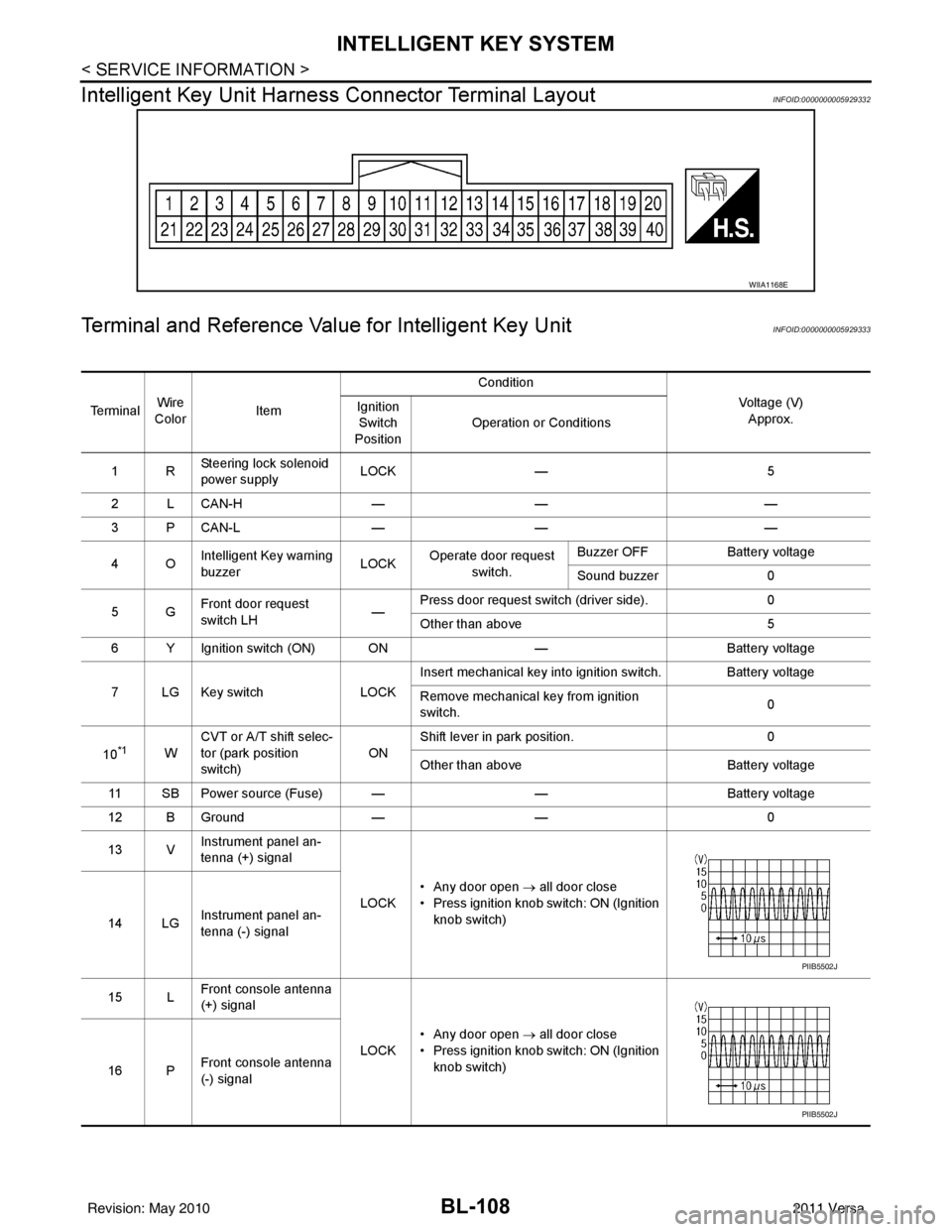
BL-108
< SERVICE INFORMATION >
INTELLIGENT KEY SYSTEM
Intelligent Key Unit Harnes s Connector Terminal Layout
INFOID:0000000005929332
Terminal and Reference Value for Intelligent Key UnitINFOID:0000000005929333
WIIA1168E
Te r m i n a lWire
Color Item Condition
Voltage (V)Approx.
Ignition
Switch
Position Operation or Conditions
1R Steering lock solenoid
power supply LOCK
— 5
2 L CAN-H —— —
3 P CAN-L —— —
4O Intelligent Key warning
buzzer LOCK
Operate door request
switch. Buzzer OFF
Battery voltage
Sound buzzer 0
5G Front door request
switch LH —Press door request switch (driver side).
0
Other than above 5
6 Y Ignition switch (ON) ON —Battery voltage
7 LG Key switch LOCKInsert mechanical key into ignition switch. Battery voltage
Remove mechanical key from ignition
switch.
0
10
*1W CVT or A/T shift selec-
tor (park position
switch)
ONShift lever in park position.
0
Other than above Battery voltage
11 SB Power source (Fuse) — —Battery voltage
12 B Ground —— 0
13 V Instrument panel an-
tenna (+) signal
LOCK• Any door open
→ all door close
• Press ignition knob switch: ON (Ignition knob switch)
14 LG Instrument panel an-
tenna (-) signal
15 L Front console antenna
(+) signal
LOCK• Any door open
→ all door close
• Press ignition knob switch: ON (Ignition knob switch)
16 P Front console antenna
(-) signal
PIIB5502J
PIIB5502J
Revision: May 2010
2011 Versa
Page 639 of 3787
INTELLIGENT KEY SYSTEMBL-129
< SERVICE INFORMATION >
C
DE
F
G H
J
K L
M A
B
BL
N
O P
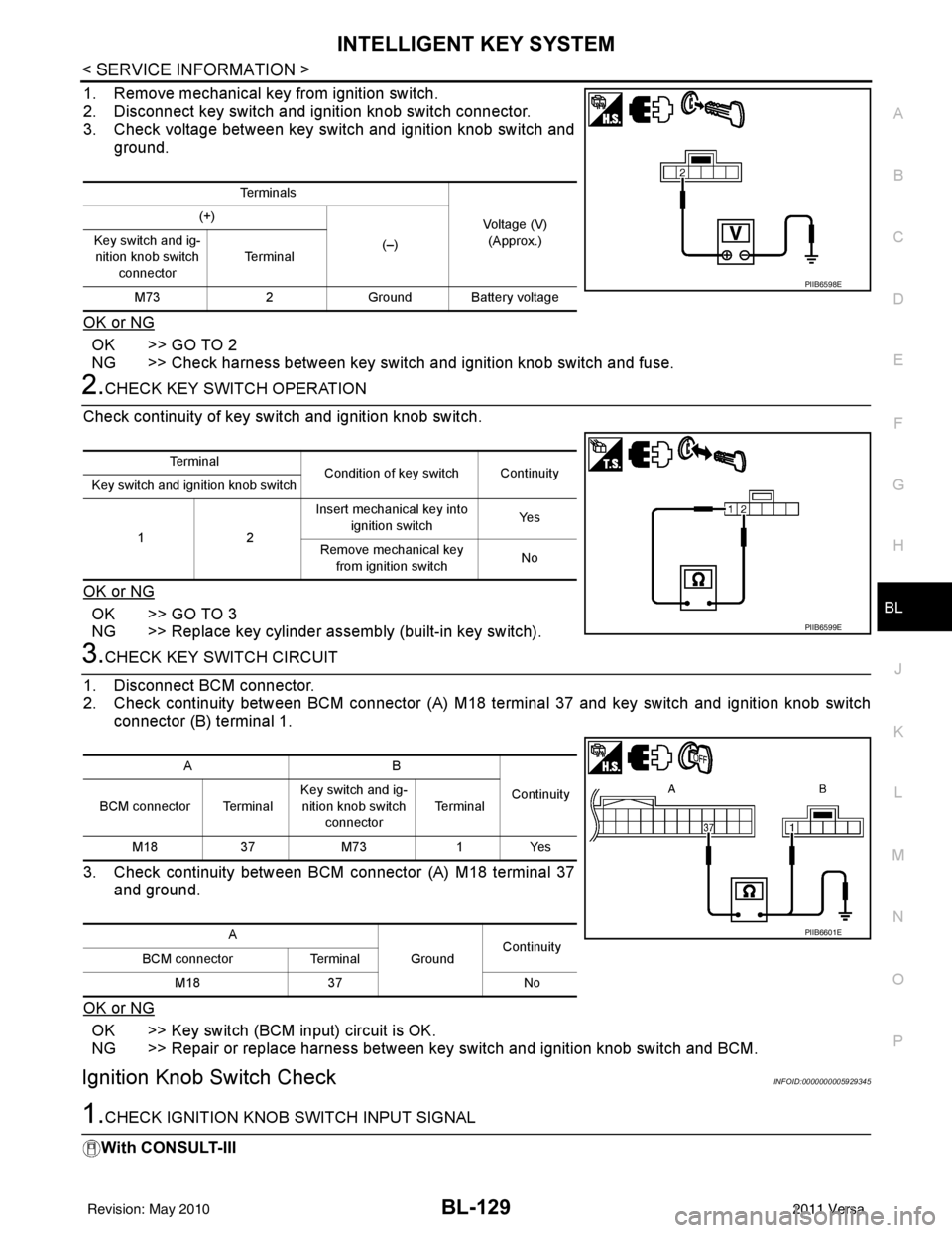
1. Remove mechanical key from ignition switch.
2. Disconnect key switch and i gnition knob switch connector.
3. Check voltage between key switch and ignition knob switch and
ground.
OK or NG
OK >> GO TO 2
NG >> Check harness between key switch and ignition knob switch and fuse.
2.CHECK KEY SWITCH OPERATION
Check continuity of key switch and ignition knob switch.
OK or NG
OK >> GO TO 3
NG >> Replace key cylinder assembly (built-in key switch).
3.CHECK KEY SWITCH CIRCUIT
1. Disconnect BCM connector.
2. Check continuity between BCM connector (A) M18 terminal 37 and key switch and ignition knob switch
connector (B) terminal 1.
3. Check continuity between BCM connector (A) M18 terminal 37 and ground.
OK or NG
OK >> Key switch (BCM input) circuit is OK.
NG >> Repair or replace harness between key switch and ignition knob switch and BCM.
Ignition Knob Switch CheckINFOID:0000000005929345
1.CHECK IGNITION KNOB SWITCH INPUT SIGNAL
With CONSULT-III
Te r m i n a l s
Voltage (V)(Approx.)
(+)
(–)
Key switch and ig-
nition knob switch
connector Te r m i n a l
M73 2Ground Battery voltage
PIIB6598E
Te r m i n a l
Condition of key switch Continuity
Key switch and ignition knob switch
12 Insert mechanical key into
ignition switch Ye s
Remove mechanical key from ignition switch No
PIIB6599E
AB
Continuity
BCM connector Terminal Key switch and ig-
nition knob switch connector Te r m i n a l
M18 37M73 1Yes
A GroundContinuity
BCM connector Terminal
M18 37 No
PIIB6601E
Revision: May 2010 2011 Versa
Page 660 of 3787
BL-150
< SERVICE INFORMATION >
INTELLIGENT KEY SYSTEM
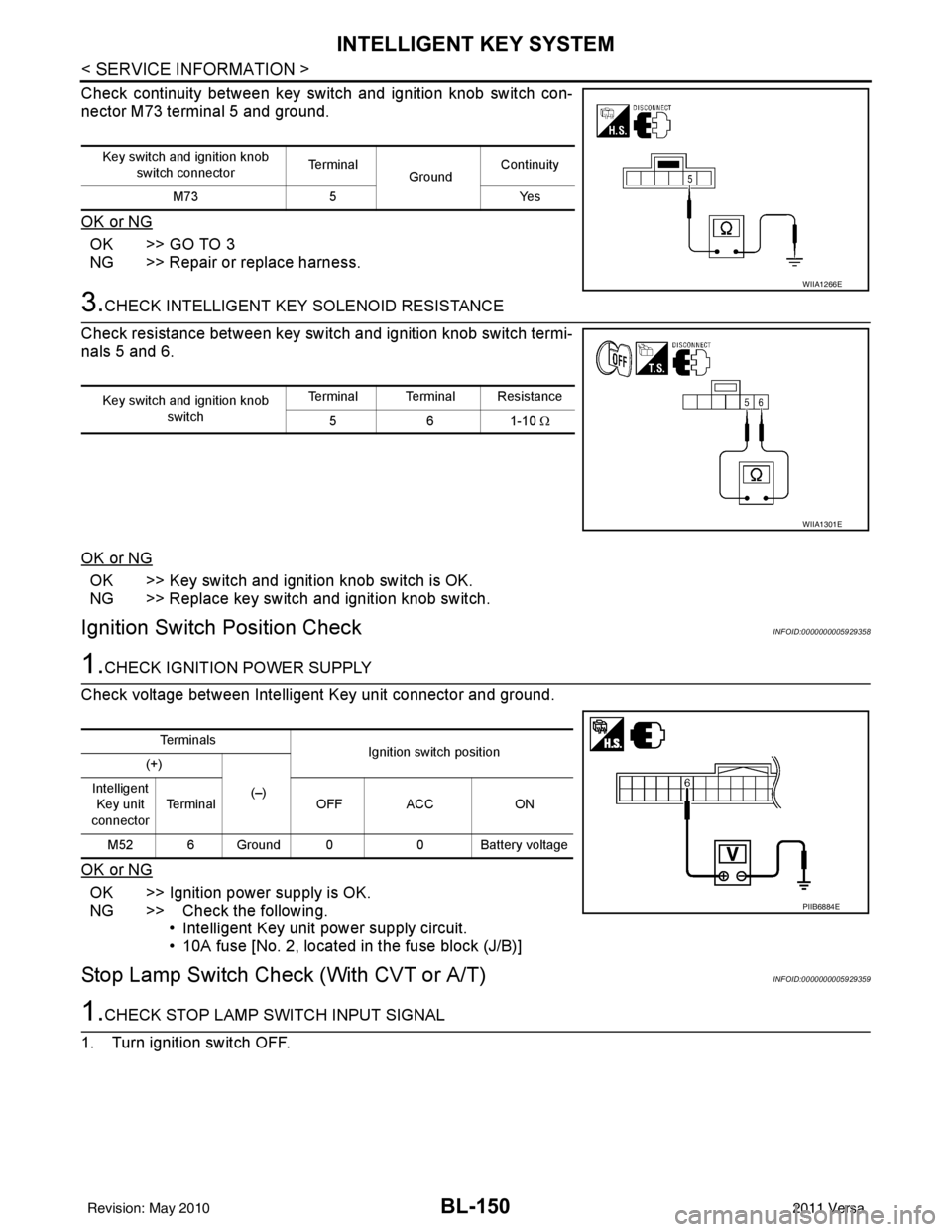
Check continuity between key switch and ignition knob switch con-
nector M73 terminal 5 and ground.
OK or NG
OK >> GO TO 3
NG >> Repair or replace harness.
3.CHECK INTELLIGENT KEY SOLENOID RESISTANCE
Check resistance between key switch and ignition knob switch termi-
nals 5 and 6.
OK or NG
OK >> Key switch and ignition knob switch is OK.
NG >> Replace key switch and ignition knob switch.
Ignition Switch Position CheckINFOID:0000000005929358
1.CHECK IGNITION POWER SUPPLY
Check voltage between Intelligent Key unit connector and ground.
OK or NG
OK >> Ignition power supply is OK.
NG >> Check the following. • Intelligent Key unit power supply circuit.
• 10A fuse [No. 2, located in the fuse block (J/B)]
Stop Lamp Switch Check (With CVT or A/T)INFOID:0000000005929359
1.CHECK STOP LAMP SWITCH INPUT SIGNAL
1. Turn ignition switch OFF.
Key switch and ignition knob switch connector Te r m i n a l
GroundContinuity
M73 5 Yes
WIIA1266E
Key switch and ignition knob
switch Terminal Terminal Resistance
561-10 Ω
WIIA1301E
Te r m i n a l s
Ignition switch position
(+)
(–)
Intelligent
Key unit
connector Terminal
OFF ACC ON
M52 6 Ground 0 0 Battery voltage
PIIB6884E
Revision: May 2010 2011 Versa
Page 661 of 3787
INTELLIGENT KEY SYSTEMBL-151
< SERVICE INFORMATION >
C
DE
F
G H
J
K L
M A
B
BL
N
O P
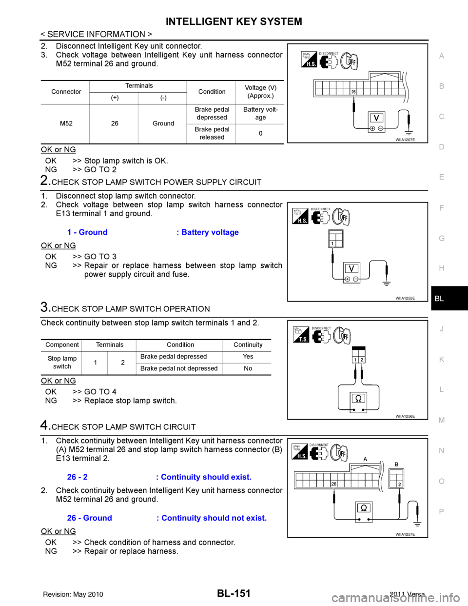
2. Disconnect Intelligent Key unit connector.
3. Check voltage between Intelligent Key unit harness connector M52 terminal 26 and ground.
OK or NG
OK >> Stop lamp switch is OK.
NG >> GO TO 2
2.CHECK STOP LAMP SWIT CH POWER SUPPLY CIRCUIT
1. Disconnect stop lamp switch connector.
2. Check voltage between stop lamp switch harness connector E13 terminal 1 and ground.
OK or NG
OK >> GO TO 3
NG >> Repair or replace harness between stop lamp switch power supply circuit and fuse.
3.CHECK STOP LAMP SWITCH OPERATION
Check continuity between stop lamp switch terminals 1 and 2.
OK or NG
OK >> GO TO 4
NG >> Replace stop lamp switch.
4.CHECK STOP LAMP SWITCH CIRCUIT
1. Check continuity between Intelligent Key unit harness connector (A) M52 terminal 26 and stop lamp switch harness connector (B)
E13 terminal 2.
2. Check continuity between Intelligent Key unit harness connector M52 terminal 26 and ground.
OK or NG
OK >> Check condition of harness and connector.
NG >> Repair or replace harness.
Connector Te r m i n a l s
ConditionVoltage (V)
(Approx.)
(+) (-)
M52 26Ground Brake pedal
depressed Battery volt-
age
Brake pedal released 0
WIIA1207E
1 - Ground
: Battery voltage
WIIA1255E
Component Terminals ConditionContinuity
Stop lamp switch 12 Brake pedal depressed
Yes
Brake pedal not depressed No
WIIA1256E
26 - 2 : Continuity should exist.
26 - Ground : Continuity should not exist.
WIIA1257E
Revision: May 2010 2011 Versa