NISSAN NAVARA 2005 Repair Workshop Manual
Manufacturer: NISSAN, Model Year: 2005, Model line: NAVARA, Model: NISSAN NAVARA 2005Pages: 3171, PDF Size: 49.59 MB
Page 1671 of 3171
CONSULT-II CHECKING SYSTEM
GI-49
C
D
E
F
G
H
I
J
K
L
MB
GI
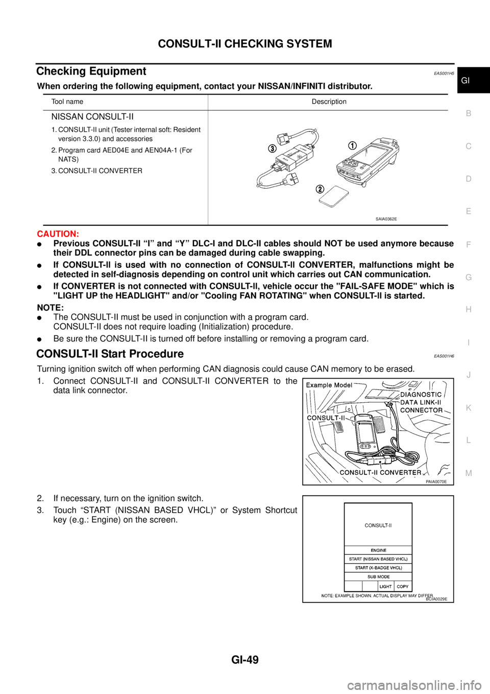
Checking EquipmentEAS001H5
When ordering the following equipment, contact your NISSAN/INFINITI distributor.
CAUTION:
lPrevious CONSULT-II “I” and “Y” DLC-I and DLC-II cables should NOT be used anymore because
their DDL connector pins can be damaged during cable swapping.
lIf CONSULT-ll is used with no connection of CONSULT-ll CONVERTER, malfunctions might be
detected in self-diagnosis depending on control unit which carries out CAN communication.
lIf CONVERTER is not connected with CONSULT-ll, vehicle occur the "FAIL-SAFE MODE" which is
"LIGHT UP the HEADLIGHT" and/or "Cooling FAN ROTATING" when CONSULT-ll is started.
NOTE:
lThe CONSULT-II must be used in conjunction with a program card.
CONSULT-II does not require loading (Initialization) procedure.
lBe sure the CONSULT-II is turned off before installing or removing a program card.
CONSULT-II Start ProcedureEAS001H6
Turning ignition switch off when performing CAN diagnosis could cause CAN memory to be erased.
1. Connect CONSULT-II and CONSULT-II CONVERTER to the
data link connector.
2. If necessary, turn on the ignition switch.
3. Touch “START (NISSAN BASED VHCL)” or System Shortcut
key (e.g.: Engine) on the screen.
Tool nameDescription
NISSAN CONSULT-II
1. CONSULT-II unit (Tester internal soft: Resident
version 3.3.0) and accessories
2. Program card AED04E and AEN04A-1 (For
NATS)
3. CONSULT-II CONVERTER
SAIA0362E
PAIA0070E
BCIA0029E
Page 1672 of 3171
GI-50
CONSULT-II CHECKING SYSTEM
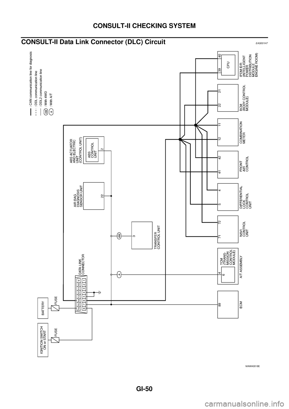
CONSULT-II Data Link Connector (DLC) Circuit
EAS001H7
MAWA0018E
Page 1673 of 3171
CONSULT-II CHECKING SYSTEM
GI-51
C
D
E
F
G
H
I
J
K
L
MB
GI
INSPECTION PROCEDURE
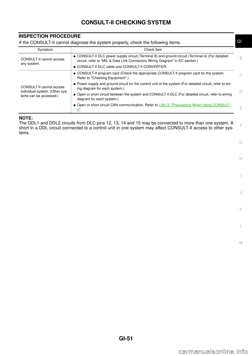
If the CONSULT-II cannot diagnose the system properly, check the following items.
NOTE:
The DDL1 and DDL2 circuits from DLC pins 12, 13, 14 and 15 may be connected to more than one system. A
short in a DDL circuit connected to a control unit in one system may affect CONSULT-II access to other sys-
tems.
Symptom Check item
CONSULT-II cannot access
any system.
lCONSULT-II DLC power supply circuit (Terminal 8) and ground circuit (Terminal 4) (For detailed
circuit, refer to “MIL & Data Link Connectors Wiring Diagram” in EC section.)
lCONSULT-II DLC cable and CONSULT-II CONVERTER.
CONSULT-II cannot access
individual system. (Other sys-
tems can be accessed.)
lCONSULT-II program card (Check the appropriate CONSULT-II program card for the system.
Refer to "Checking Equipment".)
lPower supply and ground circuit for the control unit of the system (For detailed circuit, refer to wir-
ing diagram for each system.)
lOpen or short circuit between the system and CONSULT-II DLC (For detailed circuit, refer to wiring
diagram for each system.)
lOpen or short circuit CAN communication. Refer toLAN-3, "Precautions When Using CONSULT-
II"
Page 1674 of 3171
GI-52
LIFTING POINT
LIFTING POINT
PFP:00000
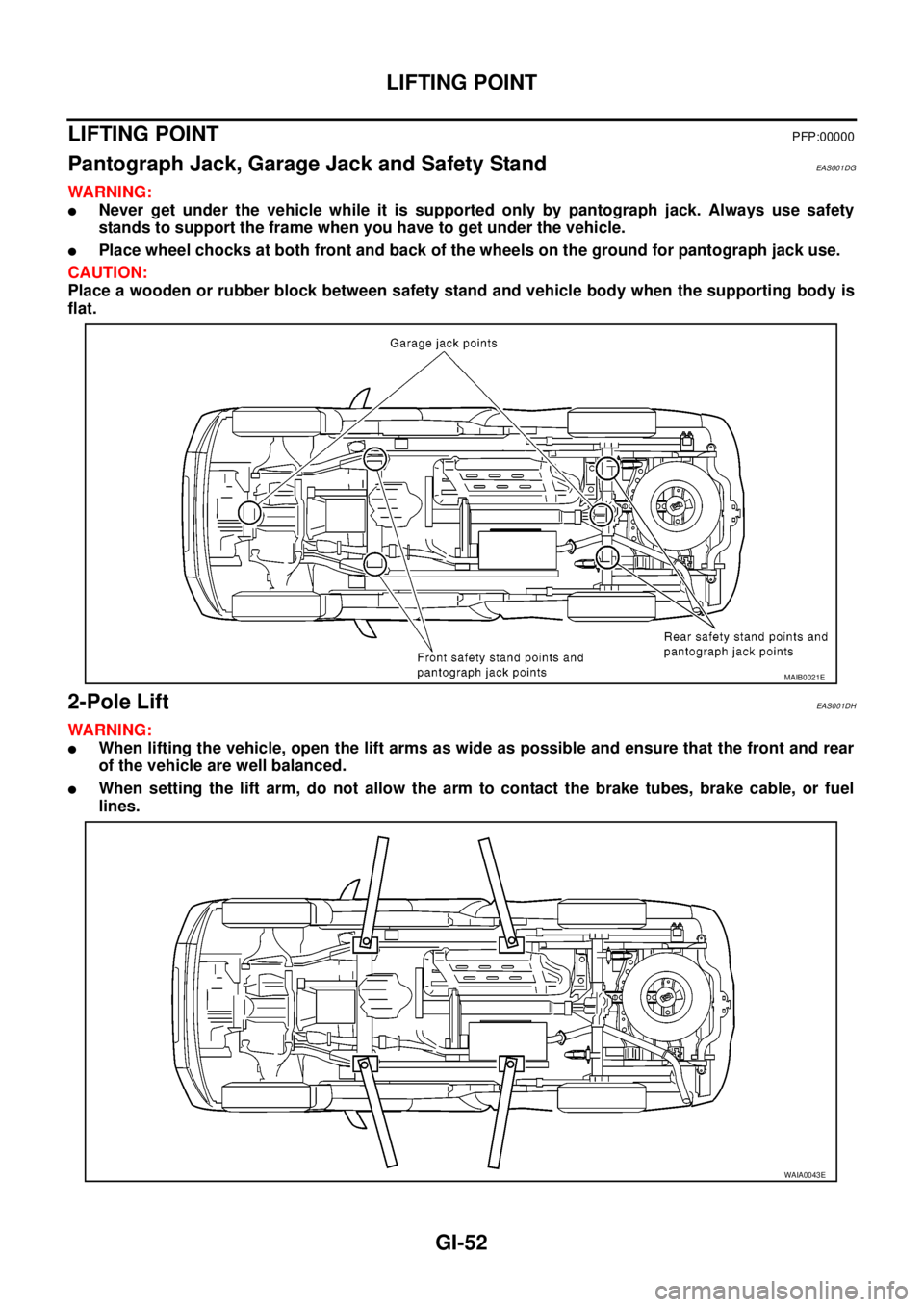
Pantograph Jack, Garage Jack and Safety StandEAS001DG
WARNING:
lNever get under the vehicle while it is supported only by pantograph jack. Always use safety
stands to support the frame when you have to get under the vehicle.
lPlace wheel chocks at both front and back of the wheels on the ground for pantograph jack use.
CAUTION:
Place a wooden or rubber block between safety stand and vehicle body when the supporting body is
flat.
2-Pole LiftEAS001DH
WARNING:
lWhen lifting the vehicle, open the lift arms as wide as possible and ensure that the front and rear
of the vehicle are well balanced.
lWhen setting the lift arm, do not allow the arm to contact the brake tubes, brake cable, or fuel
lines.
MAIB0021E
WAIA0043E
Page 1675 of 3171
TOW TRUCK TOWING
GI-53
C
D
E
F
G
H
I
J
K
L
MB
GI
TOW TRUCK TOWINGPFP:00000
To w Tr u c k To w i n gEAS001DI
WARNING:
lNever get under the vehicle while it is supported only by the jack. Always use safety stands to
support the frame when you have to get under the vehicle.
lPlace wheel chocks at both front and back of the wheels on the ground.
CAUTION:
lAll applicable local laws regarding the towing operation must be obeyed.
lIt is necessary to use proper towing equipment to avoid possible damage during towing opera-
tion. Towing is in accordance with Towing Procedure Manual at dealer.
lAlways attach safety chains before towing.
lWhen towing, make sure that the transmission, steering system and powertrain are in good order.
If any unit is damaged, dollies must be used.
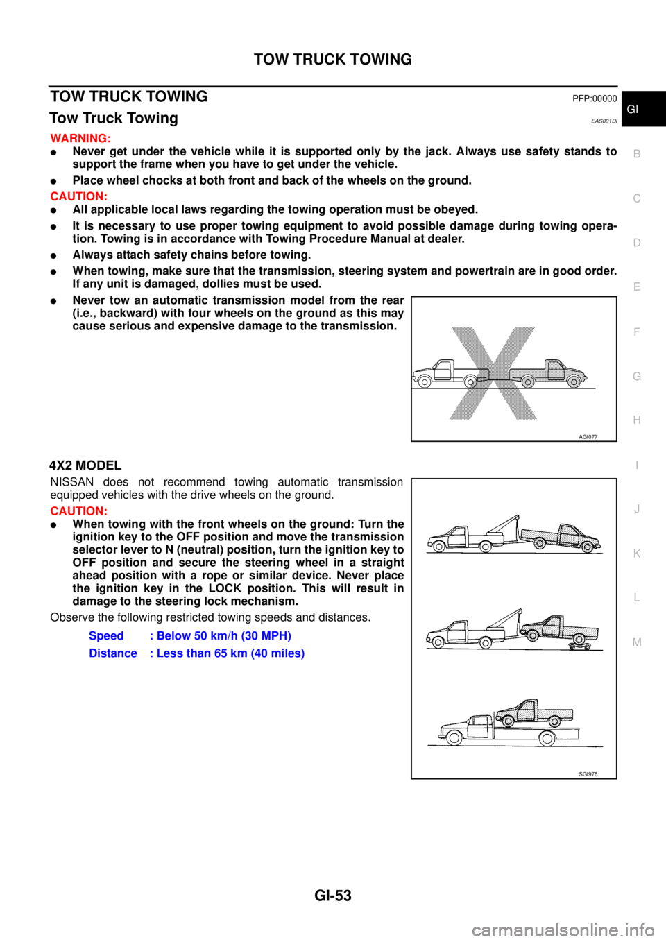
lNever tow an automatic transmission model from the rear
(i.e., backward) with four wheels on the ground as this may
cause serious and expensive damage to the transmission.
4X2 MODEL
NISSAN does not recommend towing automatic transmission
equipped vehicles with the drive wheels on the ground.
CAUTION:
lWhen towing with the front wheels on the ground: Turn the
ignition key to the OFF position and move the transmission
selector lever to N (neutral) position, turn the ignition key to
OFF position and secure the steering wheel in a straight
ahead position with a rope or similar device. Never place
the ignition key in the LOCK position. This will result in
damage to the steering lock mechanism.
Observe the following restricted towing speeds and distances.
AGI077
Speed : Below 50 km/h (30 MPH)
Distance : Less than 65 km (40 miles)
SGI976
Page 1676 of 3171
GI-54
TOW TRUCK TOWING
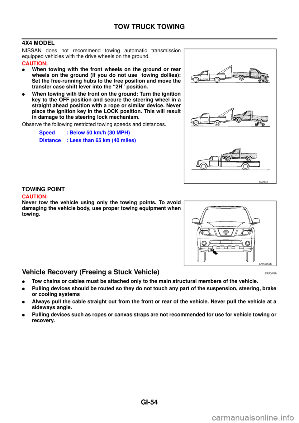
4X4 MODEL
NISSAN does not recommend towing automatic transmission
equipped vehicles with the drive wheels on the ground.
CAUTION:
lWhen towing with the front wheels on the ground or rear
wheels on the ground (If you do not use towing dollies):
Set the free-running hubs to the free position and move the
transfer case shift lever into the “2H” position.
lWhen towing with the front on the ground: Turn the ignition
key to the OFF position and secure the steering wheel in a
straight ahead position with a rope or similar device. Never
place the ignition key in the LOCK position. This will result
in damage to the steering lock mechanism.
Observe the following restricted towing speeds and distances.
TOWING POINT
CAUTION:
Never tow the vehicle using only the towing points. To avoid
damaging the vehicle body, use proper towing equipment when
towing.
Vehicle Recovery (Freeing a Stuck Vehicle)EAS001DJ
lTow chains or cables must be attached only to the main structural members of the vehicle.
lPulling devices should be routed so they do not touch any part of the suspension, steering, brake
or cooling systems
lAlways pull the cable straight out from the front or rear of the vehicle. Never pull the vehicle at a
sideways angle.
lPulling devices such as ropes or canvas straps are not recommended for use for vehicle towing or
recovery.Speed : Below 50 km/h (30 MPH)
Distance : Less than 65 km (40 miles)
SGI973
LAIA0053E
Page 1677 of 3171
TIGHTENING TORQUE OF STANDARD BOLTS
GI-55
C
D
E
F
G
H
I
J
K
L
MB
GI
TIGHTENING TORQUE OF STANDARD BOLTSPFP:00000
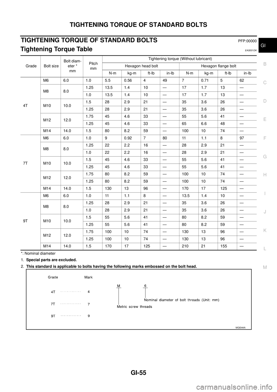
Tightening Torque TableEAS001DK
*: Nominal diameter
1.Special parts are excluded.
2.This standard is applicable to bolts having the following marks embossed on the bolt head. Grade Bolt sizeBolt diam-
eter *
mmPitch
mmTightening torque (Without lubricant)
Hexagon head bolt Hexagon flange bolt
N·m kg-m ft-lb in-lb N·m kg-m ft-lb in-lb
4TM6 6.0 1.0 5.5 0.56 4 49 7 0.71 5 62
M8 8.01.25 13.5 1.4 10 — 17 1.7 13 —
1.0 13.5 1.4 10 — 17 1.7 13 —
M10 10.01.5282.921— 353.626—
1.25 28 2.9 21 — 35 3.6 26 —
M12 12.01.75 45 4.6 33 — 55 5.6 41 —
1.25 45 4.6 33 — 65 6.6 48 —
M14 14.0 1.5 80 8.2 59 — 100 10 74 —
7TM6 6.0 1.0 9 0.92 7 80 11 1.1 8 97
M8 8.01.25 22 2.2 16 — 28 2.9 21 —
1.0222.216— 282.921—
M10 10.01.5454.633— 555.641—
1.25 45 4.6 33 — 55 5.6 41 —
M12 12.01.75 80 8.2 59 — 100 10 74 —
1.25 80 8.2 59 — 100 10 74 —
M14 14.0 1.5 130 13 96 — 170 17 125 —
9TM6 6.0 1.0 11 1.1 8 — 13.5 1.4 10 —
M8 8.01.25 28 2.9 21 — 35 3.6 26 —
1.0282.921— 353.626—
M10 10.01.5555.641— 808.259—
1.25 55 5.6 41 — 80 8.2 59 —
M12 12.01.75 100 10 74 — 130 13 96 —
1.25 100 10 74 — 130 13 96 —
M14 14.0 1.5 170 17 125 — 210 21 155 —
MGI044A
Page 1678 of 3171
GI-56
IDENTIFICATION INFORMATION
IDENTIFICATION INFORMATION
PFP:00010
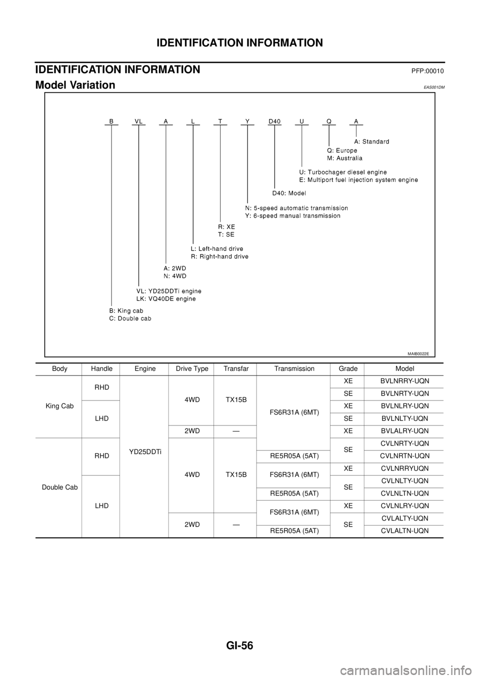
Model VariationEAS001DM
MAIB0022E
Body Handle Engine Drive Type Transfar Transmission Grade Model
King CabRHD
YD25DDTi4WD TX15B
FS6R31A (6MT)XE BVLNRRY-UQN
SE BVLNRTY-UQN
LHDXE BVLNLRY-UQN
SE BVLNLTY-UQN
2WD — XE BVLALRY-UQN
Double CabRHD
4WD TX15BSECVLNRTY-UQN
RE5R05A (5AT) CVLNRTN-UQN
FS6R31A (6MT)XE CVLNRRYUQN
LHDSECVLNLTY-UQN
RE5R05A (5AT) CVLNLTN-UQN
FS6R31A (6MT)XE CVLNLRY-UQN
2WD — SECVLALTY-UQN
RE5R05A (5AT) CVLALTN-UQN
Page 1679 of 3171
IDENTIFICATION INFORMATION
GI-57
C
D
E
F
G
H
I
J
K
L
MB
GI
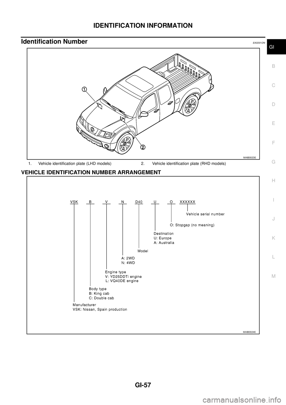
Identification NumberEAS001DN
VEHICLE IDENTIFICATION NUMBER ARRANGEMENT
1. Vehicle identification plate (LHD models) 2. Vehicle identification plate (RHD models)
MAIB0023E
MAIB0024E
Page 1680 of 3171
GI-58
IDENTIFICATION INFORMATION
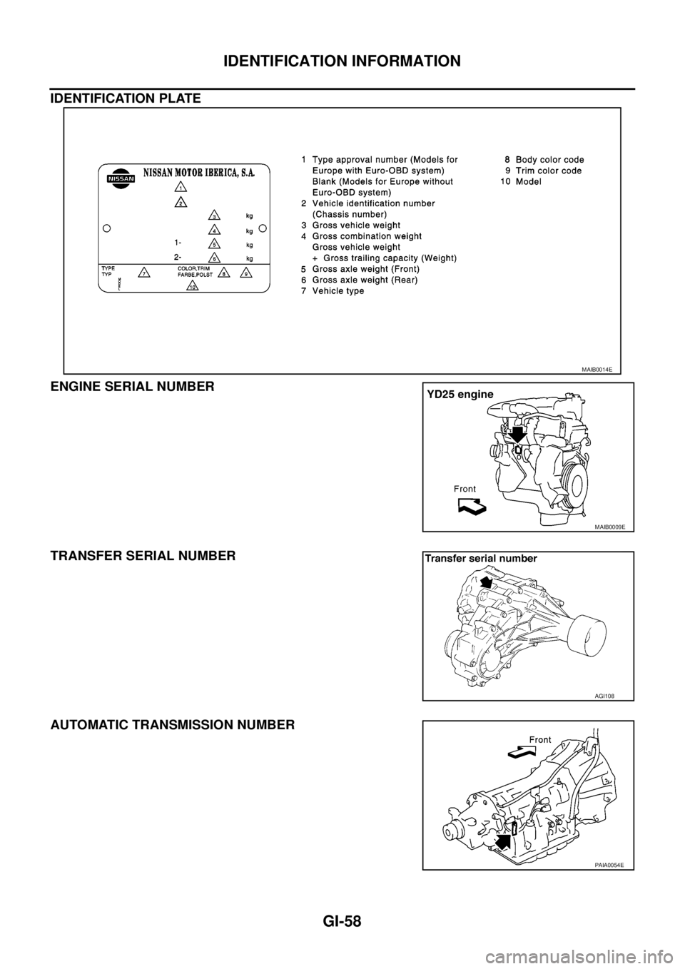
IDENTIFICATION PLATE
ENGINE SERIAL NUMBER
TRANSFER SERIAL NUMBER
AUTOMATIC TRANSMISSION NUMBER
MAIB0014E
MAIB0009E
AGI108
PAIA0054E