NISSAN NAVARA 2005 Repair Workshop Manual
Manufacturer: NISSAN, Model Year: 2005, Model line: NAVARA, Model: NISSAN NAVARA 2005Pages: 3171, PDF Size: 49.59 MB
Page 1701 of 3171
POWER WINDOW SYSTEM
GW-15
C
D
E
F
G
H
J
K
L
MA
B
GW
POWER WINDOW SYSTEMPFP:25401
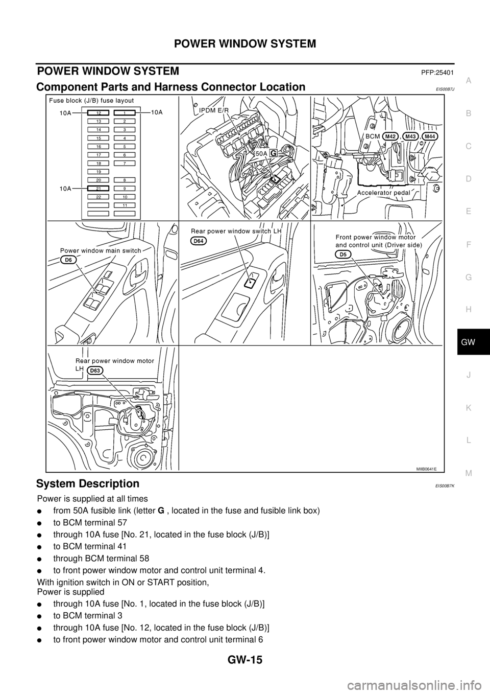
Component Parts and Harness Connector LocationEIS00B7J
System DescriptionEIS00B7K
Power is supplied at all times
lfrom 50A fusible link (letterG, located in the fuse and fusible link box)
lto BCM terminal 57
lthrough 10A fuse [No. 21, located in the fuse block (J/B)]
lto BCM terminal 41
lthrough BCM terminal 58
lto front power window motor and control unit terminal 4.
With ignition switch in ON or START position,
Power is supplied
lthrough 10A fuse [No. 1, located in the fuse block (J/B)]
lto BCM terminal 3
lthrough 10A fuse [No. 12, located in the fuse block (J/B)]
lto front power window motor and control unit terminal 6
MIIB0641E
Page 1702 of 3171

GW-16
POWER WINDOW SYSTEM
lthrough BCM terminal 53
lto power window main switch terminal 2
lto ftont power window switch (passenger side) terminal 1
lto rear power window switches LH and RH terminal 1 (with rear power window).
Ground is supplied
lto BCM terminal 55
lto front power window motor and control unit terminal 3
lto power window main switch terminal 3
lthrough body grounds M21, M80 and M83.
MANUAL OPERATION
Front Driver Side Door
WINDOW UP
When the driver side switch in the power window main switch is pressed in the up position,
Ground is supplied
lto front power window motor and control unit terminal 2
lthrough power window main switch terminal 4
lthrough power window main switch terminal 3
Then, the motor raises the window until the switch is released.
WINDOW DOWN
When the driver side switch in the power window main switch is pressed in the down position
Ground is supplied
lto front power window motor and control unit terminal 1
lthrough power window main switch terminal 5
lthrough power window main switch terminal 3
Then, the motor lowers the window until the switch is released.
Front Passenger Side Door
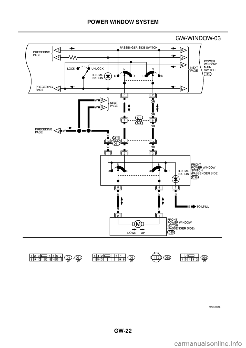
FRONT POWER WINDOW SWITCH (PASSENGER SIDE) OPERATION
WINDOW UP
When the front power window switch (passenger side) is operated in the up position
Power is supplied
lthrough front power window switch (passenger side) terminal 1 and 5
lto front power window motor (passenger side) terminal 2.
Ground is supplied
lto front power window motor (passenger side) terminal 1
lthrough front power window switch (passenger side) terminal 4 and 3
lthrough power window main switch terminal 7
Then, the motor raises the window until the switch is released.
WINDOW DOWN
When the front power window switch (passenger side) is opeataed in the down position
Power is supplied
lthrough front power window switch (passenger side) terminal 1 and 4
lto front power window motor (passenger side) terminal 1.
Ground is supplied
lto front power window motor (passenger side) terminal 2
lthrough front power window switch (passenger side) terminal 5 and 2
lthrough power window main switch terminal 6
Then, the motor lowers the window until the switch is released.
POWER WINDOW MAIN SWITCH OPERATION
WINDOW UP
When the passenger side switch in power window main switch is operated in the up position
Power is supplied
Page 1703 of 3171

POWER WINDOW SYSTEM
GW-17
C
D
E
F
G
H
J
K
L
MA
B
GW
lthrough power window main switch terminal 6
lto front power window switch (passenger side) terminal 2 and 5
lto front power window motor (passenger side) terminal 2.
Ground is supplied
lto front power window motor (passenger side) terminal 1
lthrough front power window switch (passenger side) terminal 4 and 3
lthrough power window main switch terminal 7
Then, the motor raises the window until the switch is released.
WINDOW DOWN
When the passenger side switch in power window main switch is operated in the down position
Power is supplied
lthrough power window main switch terminal 7
lto front power window switch (passenger side) terminal 3 and 4
lto front power window motor (passenger side) terminal 1.
Ground is supplied
lto front power window motor (passenger side) terminal 2
lthrough front power window switch (passenger side) terminal 5 and 2
lthrough power window main switch terminal 6
Then, the motor lowers the window until the switch is released.
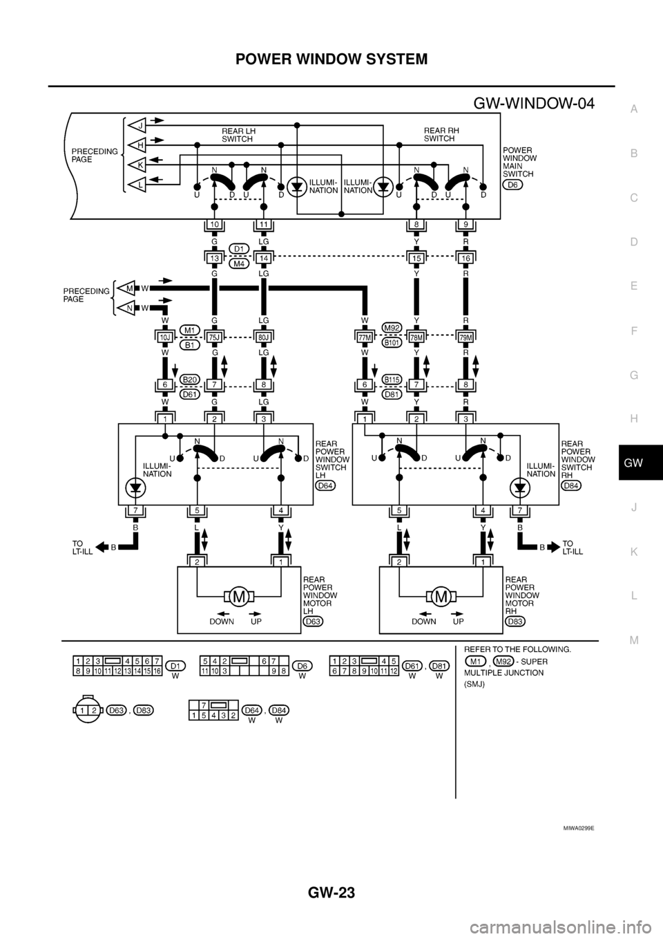
Rear Door (LH or RH)
REAR POWER WINDOW SWITCH LH OR RH OPERATION
WINDOW UP
When the rear power window switch LH or RH is operated in the up position
Power is supplied
lthrough rear power window switch LH or RH terminal 1 and 5
lto rear power window motor LH or RH terminal 1.
Ground is supplied
lto rear power window motor LH or RH terminal 2
lthrough rear power window switch LH or RH terminal 4 and 3
lthrough power window main switch 11 (LH) or 9 (RH)
Then, the motor raises the window until the switch is released.
WINDOW DOWN
When the rear power window switch LH or RH is pressed in the down position
Power is supplied
lthrough rear power window switch LH or RH terminal 1 and 4
lto rear power window motor LH or RH terminal 2.
Ground is supplied
lto rear power window motor LH or RH terminal 1
lthrough rear power window switch LH or RH terminal 5 and 2
lthrough power window main switch 1 (LH) or 7 (RH)
Then, the motor lowers the window until the switch is released.
POWERWINDOWMAINSWITCHOPERATION
WINDOW UP
When the rear LH or RH switch in the power window main switch is operated in the up position
Power is supplied
lthrough power window main switch terminal 10 (LH) or 8 (RH)
lto rear power window switch LH or RH terminal 5 and 2
lto rear power window motor LH or RH terminal 1.
Ground is supplied
lto rear power window motor LH or RH terminal 2
lthrough rear power window switch LH or RH terminal 4 and 3
Page 1704 of 3171

GW-18
POWER WINDOW SYSTEM
lthrough power window main switch terminal 11 (LH) or 9 (RH).
Then, the motor raises the window until the switch is released.
WINDOW DOWN
When the rear LH or RH switch in the power window main switch is operated in the down position
Power is supplied
lthrough power window main switch terminal 11 (LH) or 9 (RH)
lto rear power window switch LH or RH terminal 4 and 3
lto rear power window motor LH or RH terminal 2.
Ground is supplied
lto rear power window motor LH or RH terminal 1
lthrough rear power window switch LH or RH terminal 5 and 2
lthrough power window main switch terminal 10 (LH) or 8 (RH).
Then, the motor raises the window until the switch is released.
AUTO OPERATION
The power window AUTO feature enables the driver to open the window without holding the window switch in
thedownposition.
POWER WINDOW LOCK
The power window lock is designed to lock operation of all windows except for front door window LH and RH.
When in the lock position, the power window lock disables power window and door lock/unlock switch RH and
rear power window switch LH and RH by disconnecting switch ground signal. This prevents the power window
motors from operating.
DRIVER WINDOW ANTI-PINCH FUNCTION
During raising operation of driver side window, if door control module detects that foreign object is pinched,
power window lowers approximately 150 mm (5.91 in).
NOTE:
Depending on environment and driving conditions, if a similar impact or load is applied to power window, it
may lower.
Operation Conditions
lDriver side window is between fully-open and just before fully-closed position (when the limit switch is
ON).
lDuring automatic operation when ignition switch is turned ON.
lDuring automatic or manual operation when ignition switch is other than ON position (when the timer
operates).
Page 1705 of 3171
POWER WINDOW SYSTEM
GW-19
C
D
E
F
G
H
J
K
L
MA
B
GW
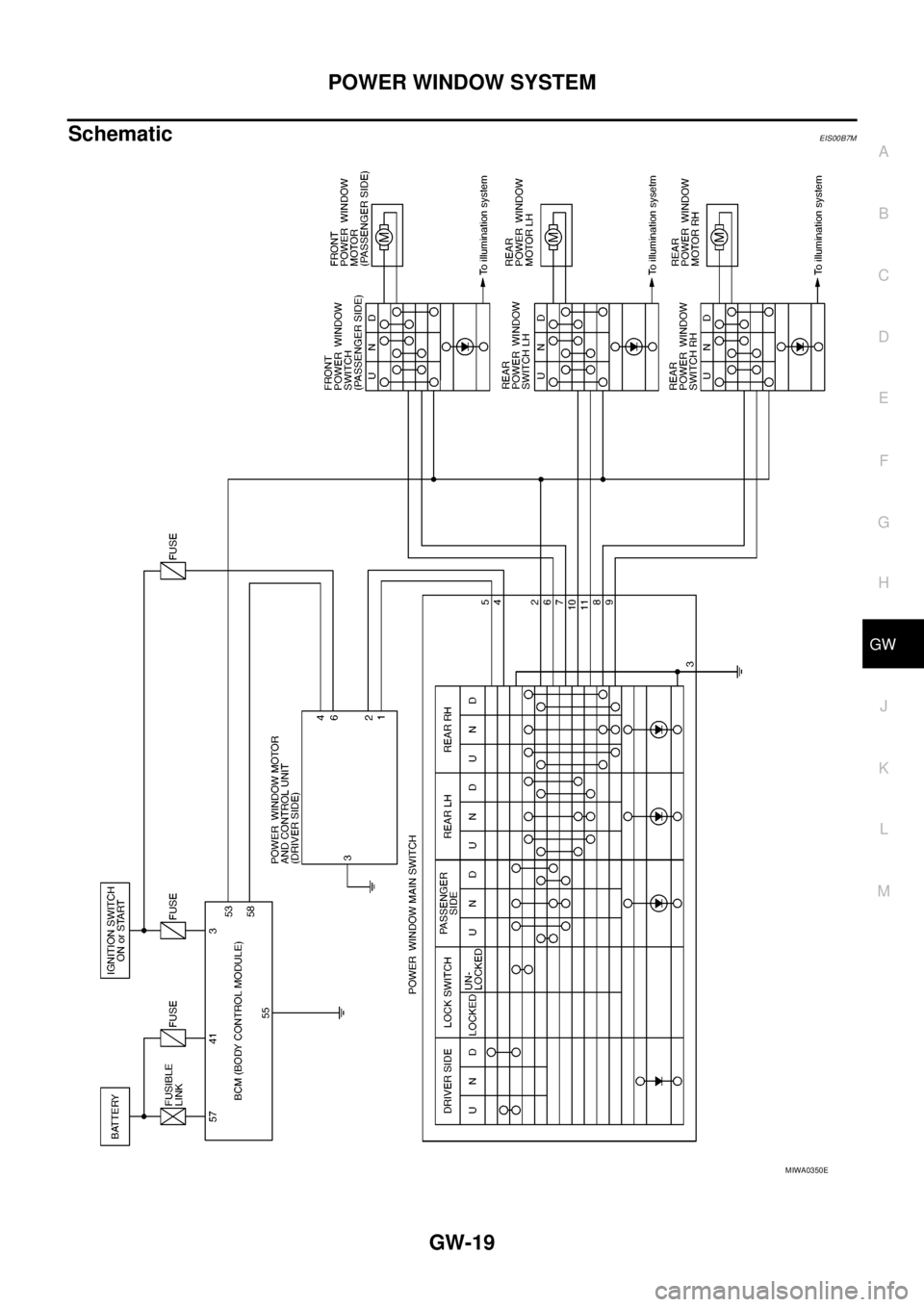
SchematicEIS00B7M
MIWA0350E
Page 1706 of 3171
GW-20
POWER WINDOW SYSTEM
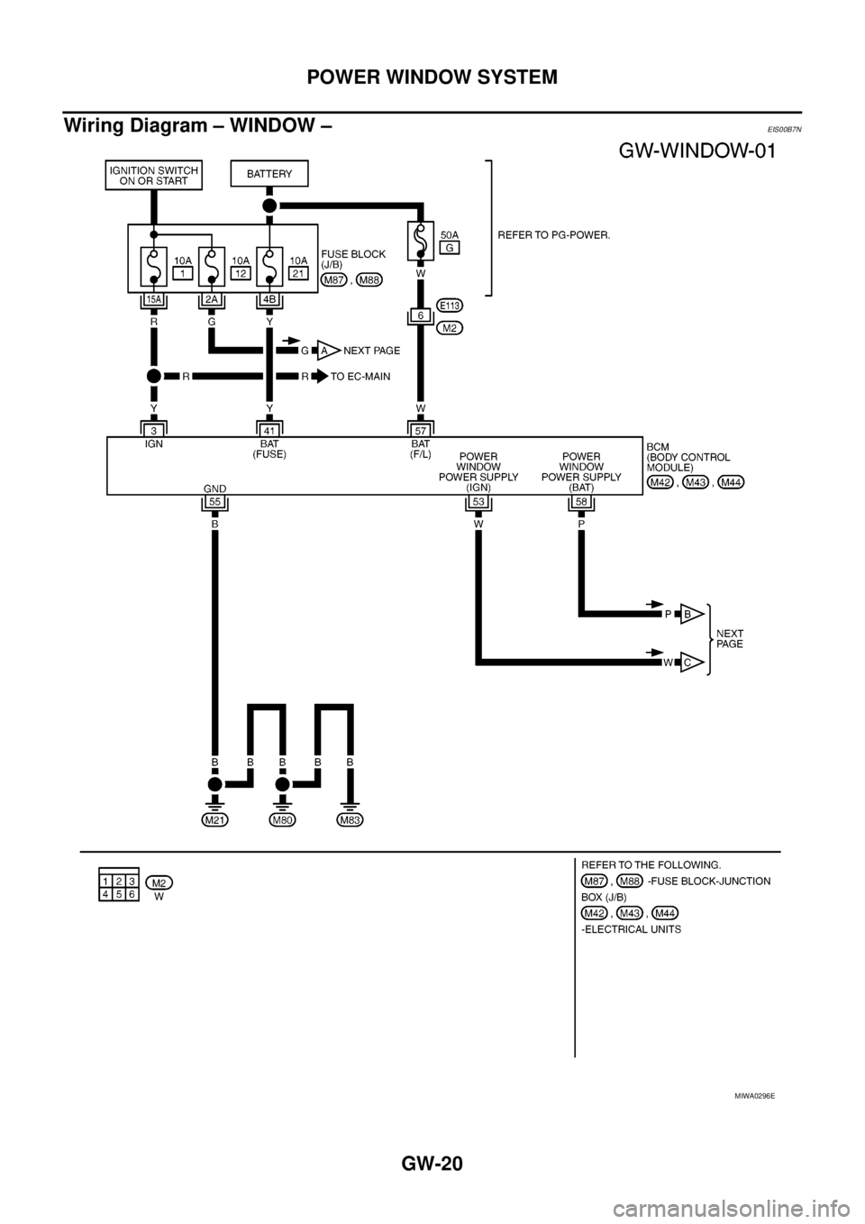
Wiring Diagram – WINDOW –
EIS00B7N
MIWA0296E
Page 1707 of 3171
POWER WINDOW SYSTEM
GW-21
C
D
E
F
G
H
J
K
L
MA
B
GW
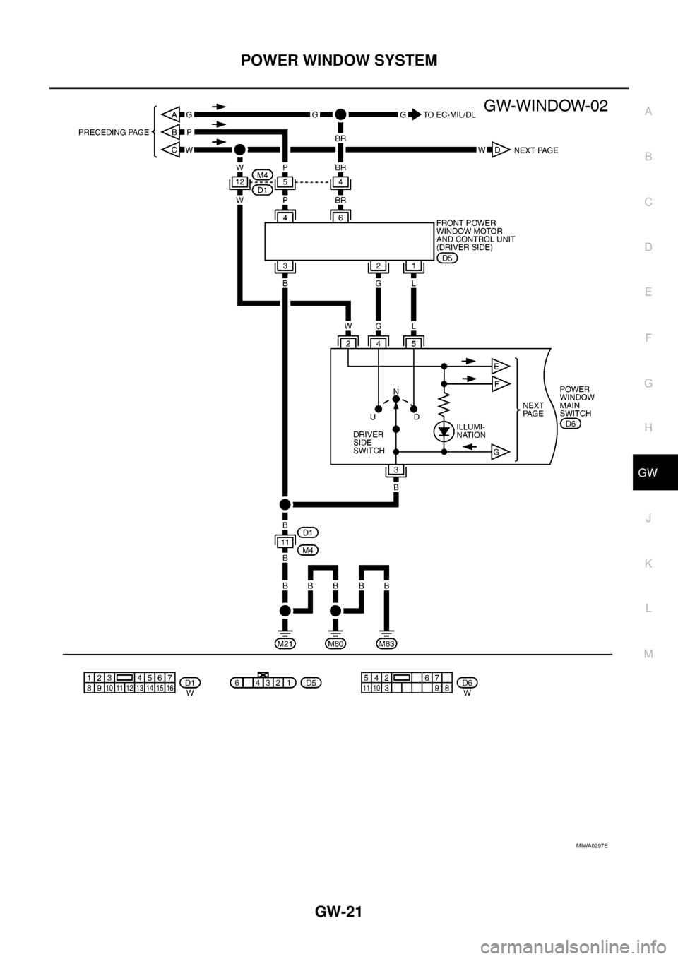
MIWA0297E
Page 1708 of 3171
GW-22
POWER WINDOW SYSTEM
MIWA0351E
Page 1709 of 3171
POWER WINDOW SYSTEM
GW-23
C
D
E
F
G
H
J
K
L
MA
B
GW
MIWA0299E
Page 1710 of 3171

GW-24
POWER WINDOW SYSTEM
Terminal and Reference Value for Power Window Main Switch
EIS00C08
Terminal and Reference Value for Each Door's Power Window SwitchEIS00C09
*1:RearLH
*2:RearRH TerminalWire
colorItem ConditionVoltage (V)
(Approx.)
2 W IGN power supply Ignition switch (ON or START position) Battery voltage
3 B Ground — 0
4 G Driver power window motor UP signalDriver side switch UP operation 0
Other than above Battery voltage
5 L Driver power window motor DOWN signalDriver side switch DOWN operation 0
Other than above Battery voltage
6 L Passenger power window motor UP signalPassenger side switch UP operation Battery voltage
Other than above 0
7GRPassenger power window motor DOWN
signalPassenger side switch DOWN operation Battery voltage
Other than above 0
8 Y Rear RH power window motor UP signalRear RH switch UP operation Battery voltage
Other than above 0
9RRear RH power window motor DOWN sig-
nalRear RH switch DOWN operation Battery voltage
Other than above 0
10 G Rear LH power window motor UP signalRear LH switch UP operation Battery voltage
Other than above 0
11 L GRear LH power window motor DOWN sig-
nalRear LH switch DOWN operation Battery voltage
Other than above 0
TerminalWire
colorItem ConditionVo l ta g e (V )
(Approx.)
1 W IGN power supply Ignition switch (ON or START position) Battery voltage
2L
G*
1
Y*2
Power window UP signal
from power window main switchPower window main switch
UP operationBattery voltage
Other than above 0
3L
LG*
1
R*2
Power window DOWN signal
from power window main switchPower window main switch
DOWN operationBattery voltage
Other than above 0
4L
Y*
1
Y*2Power window motor DOWN signalWhen DOWN operation Battery voltage
Other than above 0
5G
L*
1
L*2Power window motor UP signalWhen UP operation Battery voltage
Other than above 0