transmission NISSAN NAVARA 2005 Repair Workshop Manual
[x] Cancel search | Manufacturer: NISSAN, Model Year: 2005, Model line: NAVARA, Model: NISSAN NAVARA 2005Pages: 3171, PDF Size: 49.59 MB
Page 2364 of 3171
TRANSMISSION ASSEMBLY
MT-47
D
E
F
G
H
I
J
K
L
MA
B
MT
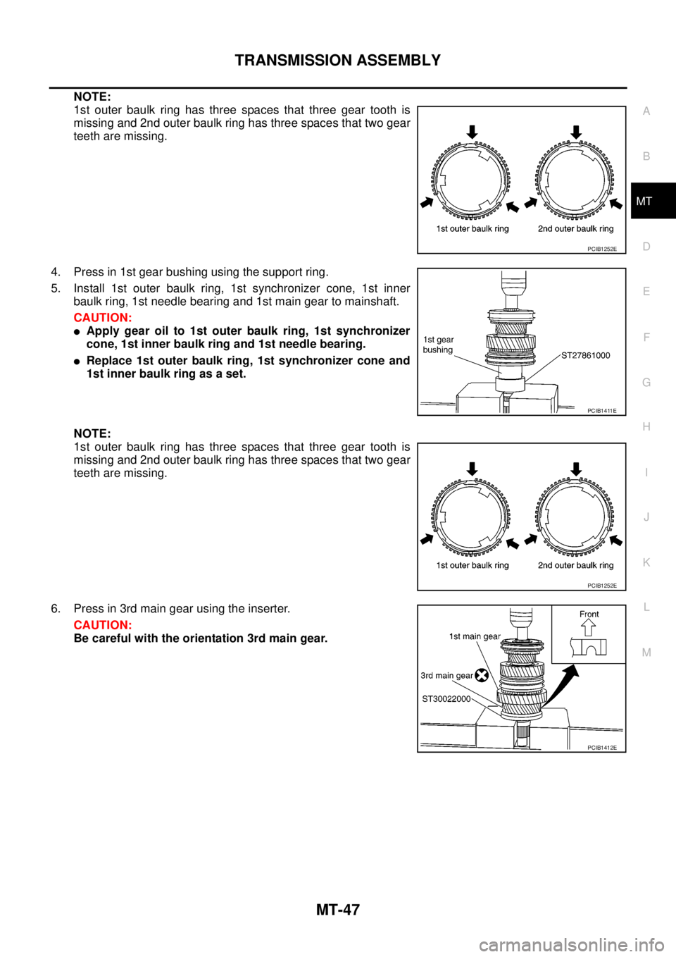
NOTE:
1st outer baulk ring has three spaces that three gear tooth is
missing and 2nd outer baulk ring has three spaces that two gear
teeth are missing.
4. Press in 1st gear bushing using the support ring.
5. Install 1st outer baulk ring, 1st synchronizer cone, 1st inner
baulk ring, 1st needle bearing and 1st main gear to mainshaft.
CAUTION:
lApply gear oil to 1st outer baulk ring, 1st synchronizer
cone, 1st inner baulk ring and 1st needle bearing.
lReplace 1st outer baulk ring, 1st synchronizer cone and
1st inner baulk ring as a set.
NOTE:
1st outer baulk ring has three spaces that three gear tooth is
missing and 2nd outer baulk ring has three spaces that two gear
teeth are missing.
6. Press in 3rd main gear using the inserter.
CAUTION:
Be careful with the orientation 3rd main gear.
PCIB1252E
PCIB1411E
PCIB1252E
PCIB1412E
Page 2365 of 3171
MT-48
TRANSMISSION ASSEMBLY
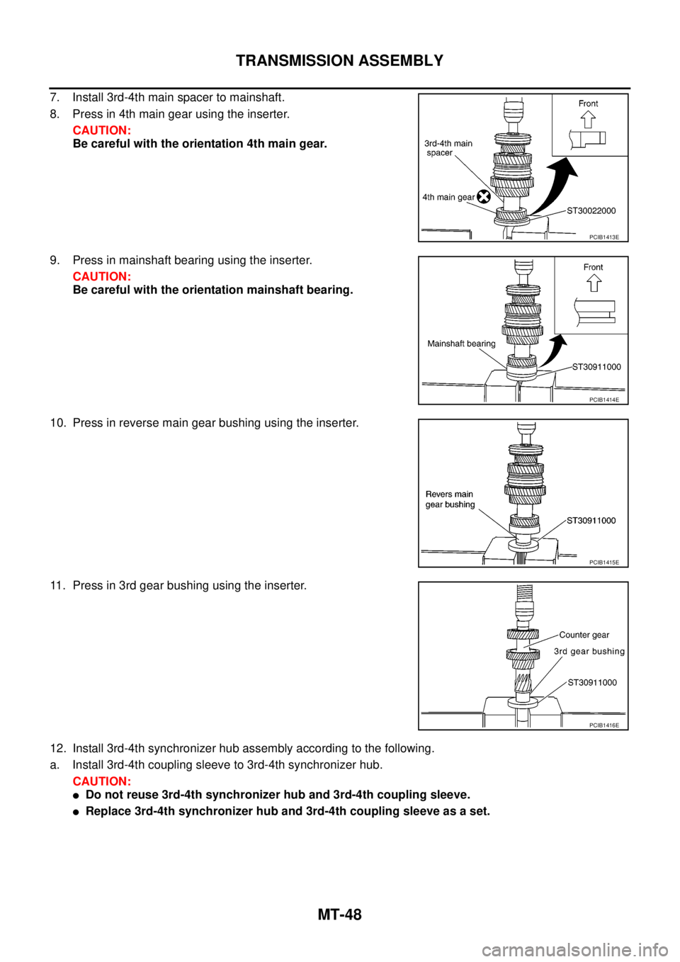
7. Install 3rd-4th main spacer to mainshaft.
8. Press in 4th main gear using the inserter.
CAUTION:
Be careful with the orientation 4th main gear.
9. Press in mainshaft bearing using the inserter.
CAUTION:
Be careful with the orientation mainshaft bearing.
10. Press in reverse main gear bushing using the inserter.
11. Press in 3rd gear bushing using the inserter.
12. Install 3rd-4th synchronizer hub assembly according to the following.
a. Install 3rd-4th coupling sleeve to 3rd-4th synchronizer hub.
CAUTION:
lDo not reuse 3rd-4th synchronizer hub and 3rd-4th coupling sleeve.
lReplace 3rd-4th synchronizer hub and 3rd-4th coupling sleeve as a set.
PCIB1413E
PCIB1414E
PCIB1415E
PCIB1416E
Page 2366 of 3171
TRANSMISSION ASSEMBLY
MT-49
D
E
F
G
H
I
J
K
L
MA
B
MT
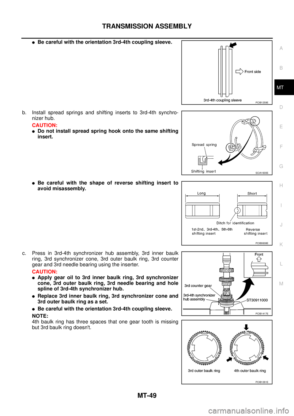
lBe careful with the orientation 3rd-4th coupling sleeve.
b. Install spread springs and shifting inserts to 3rd-4th synchro-
nizer hub.
CAUTION:
lDo not install spread spring hook onto the same shifting
insert.
lBe careful with the shape of reverse shifting insert to
avoid misassembly.
c. Press in 3rd-4th synchronizer hub assembly, 3rd inner baulk
ring, 3rd synchronizer cone, 3rd outer baulk ring, 3rd counter
gear and 3rd needle bearing using the inserter.
CAUTION:
lApply gear oil to 3rd inner baulk ring, 3rd synchronizer
cone, 3rd outer baulk ring, 3rd needle bearing and hole
spline of 3rd-4th synchronizer hub.
lReplace 3rd inner baulk ring, 3rd synchronizer cone and
3rd outer baulk ring as a set.
lBe careful with the orientation 3rd-4th coupling sleeve.
NOTE:
4th baulk ring has three spaces that one gear tooth is missing
but 3rd baulk ring doesn't.
PCIB1259E
SCIA1600E
PCIB0608E
PCIB1417E
PCIB1261E
Page 2367 of 3171
MT-50
TRANSMISSION ASSEMBLY
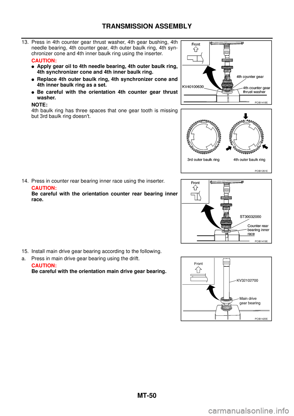
13. Press in 4th counter gear thrust washer, 4th gear bushing, 4th
needle bearing, 4th counter gear, 4th outer baulk ring, 4th syn-
chronizer cone and 4th inner baulk ring using the inserter.
CAUTION:
lApply gear oil to 4th needle bearing, 4th outer baulk ring,
4th synchronizer cone and 4th inner baulk ring.
lReplace 4th outer baulk ring, 4th synchronizer cone and
4th inner baulk ring as a set.
lBe careful with the orientation 4th counter gear thrust
washer.
NOTE:
4th baulk ring has three spaces that one gear tooth is missing
but 3rd baulk ring doesn't.
14. Press in counter rear bearing inner race using the inserter.
CAUTION:
Be careful with the orientation counter rear bearing inner
race.
15. Install main drive gear bearing according to the following.
a. Press in main drive gear bearing using the drift.
CAUTION:
Be careful with the orientation main drive gear bearing.
PCIB1418E
PCIB1261E
PCIB1419E
PCIB1420E
Page 2368 of 3171
TRANSMISSION ASSEMBLY
MT-51
D
E
F
G
H
I
J
K
L
MA
B
MT
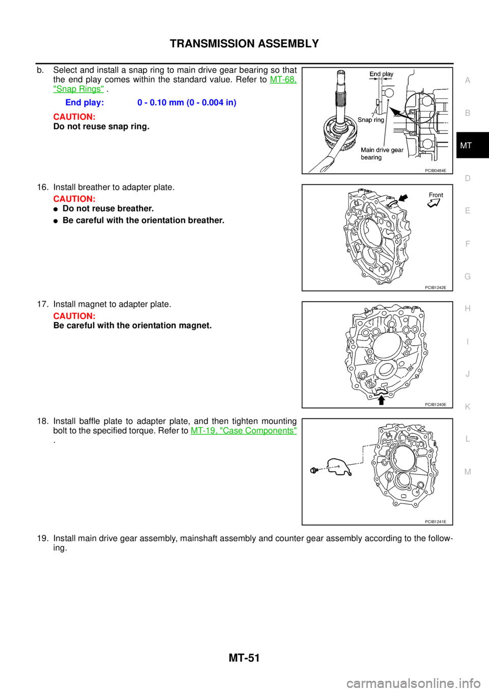
b. Selectandinstallasnapringtomaindrivegearbearingsothat
the end play comes within the standard value. Refer toMT-68,
"Snap Rings".
CAUTION:
Do not reuse snap ring.
16. Install breather to adapter plate.
CAUTION:
lDo not reuse breather.
lBe careful with the orientation breather.
17. Install magnet to adapter plate.
CAUTION:
Be careful with the orientation magnet.
18. Install baffle plate to adapter plate, and then tighten mounting
bolt to the specified torque. Refer toMT-19, "
Case Components"
.
19. Install main drive gear assembly, mainshaft assembly and counter gear assembly according to the follow-
ing.End play: 0 - 0.10 mm (0 - 0.004 in)
PCIB0484E
PCIB1242E
PCIB1240E
PCIB1241E
Page 2369 of 3171
MT-52
TRANSMISSION ASSEMBLY
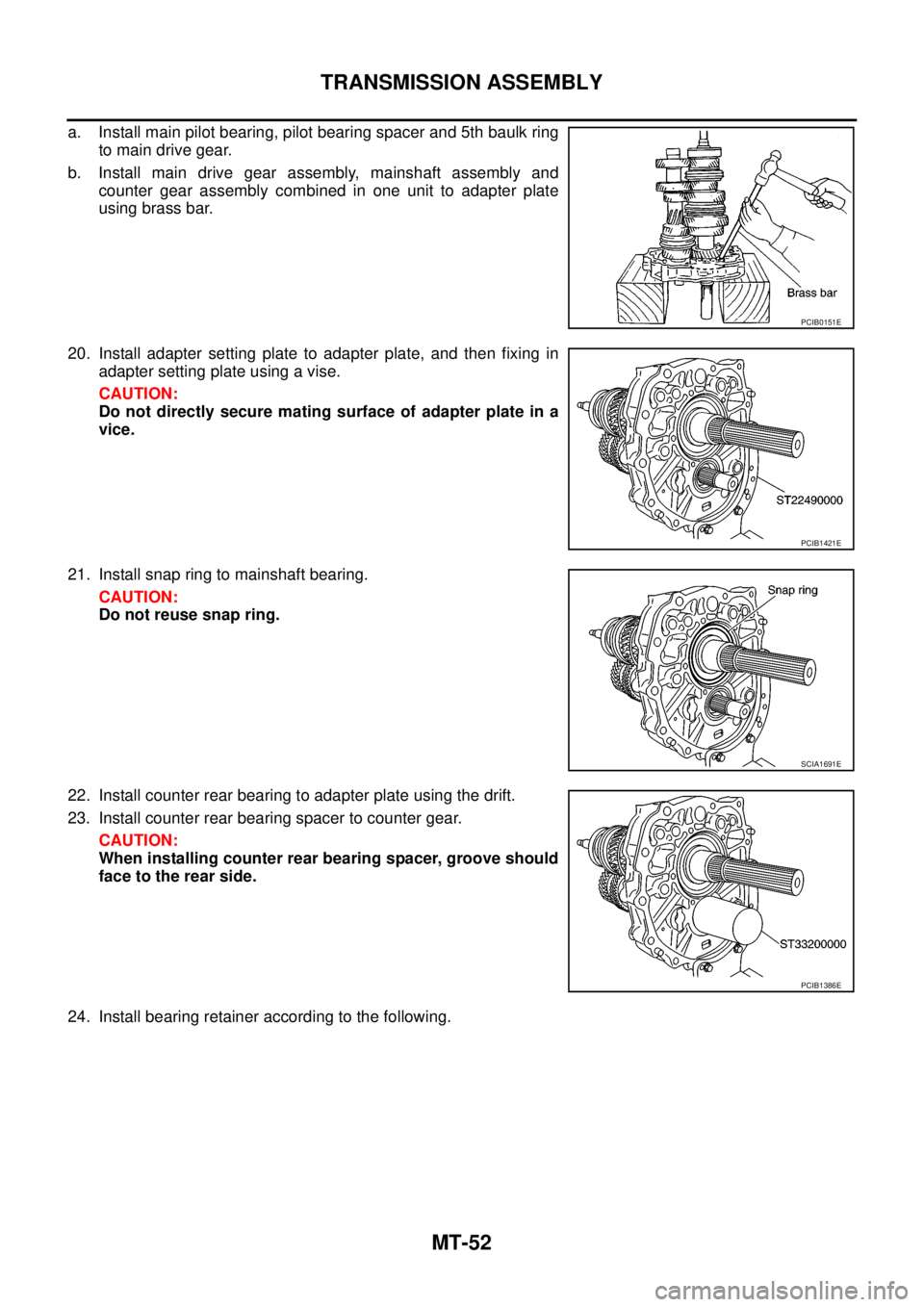
a. Install main pilot bearing, pilot bearing spacer and 5th baulk ring
to main drive gear.
b. Install main drive gear assembly, mainshaft assembly and
counter gear assembly combined in one unit to adapter plate
using brass bar.
20. Install adapter setting plate to adapter plate, and then fixing in
adapter setting plate using a vise.
CAUTION:
Do not directly secure mating surface of adapter plate in a
vice.
21. Install snap ring to mainshaft bearing.
CAUTION:
Do not reuse snap ring.
22. Install counter rear bearing to adapter plate using the drift.
23. Install counter rear bearing spacer to counter gear.
CAUTION:
When installing counter rear bearing spacer, groove should
face to the rear side.
24. Install bearing retainer according to the following.
PCIB0151E
PCIB1421E
SCIA1691E
PCIB1386E
Page 2370 of 3171
TRANSMISSION ASSEMBLY
MT-53
D
E
F
G
H
I
J
K
L
MA
B
MT
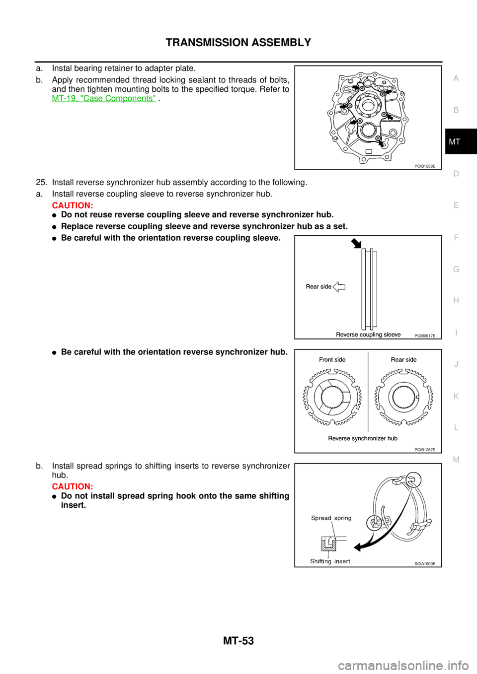
a. Instal bearing retainer to adapter plate.
b. Apply recommended thread locking sealant to threads of bolts,
and then tighten mounting bolts to the specified torque. Refer to
MT-19, "
Case Components".
25. Install reverse synchronizer hub assembly according to the following.
a. Install reverse coupling sleeve to reverse synchronizer hub.
CAUTION:
lDo not reuse reverse coupling sleeve and reverse synchronizer hub.
lReplace reverse coupling sleeve and reverse synchronizer hub as a set.
lBe careful with the orientation reverse coupling sleeve.
lBe careful with the orientation reverse synchronizer hub.
b. Install spread springs to shifting inserts to reverse synchronizer
hub.
CAUTION:
lDo not install spread spring hook onto the same shifting
insert.
PCIB1238E
PCIB0617E
PCIB1267E
SCIA1600E
Page 2371 of 3171
MT-54
TRANSMISSION ASSEMBLY
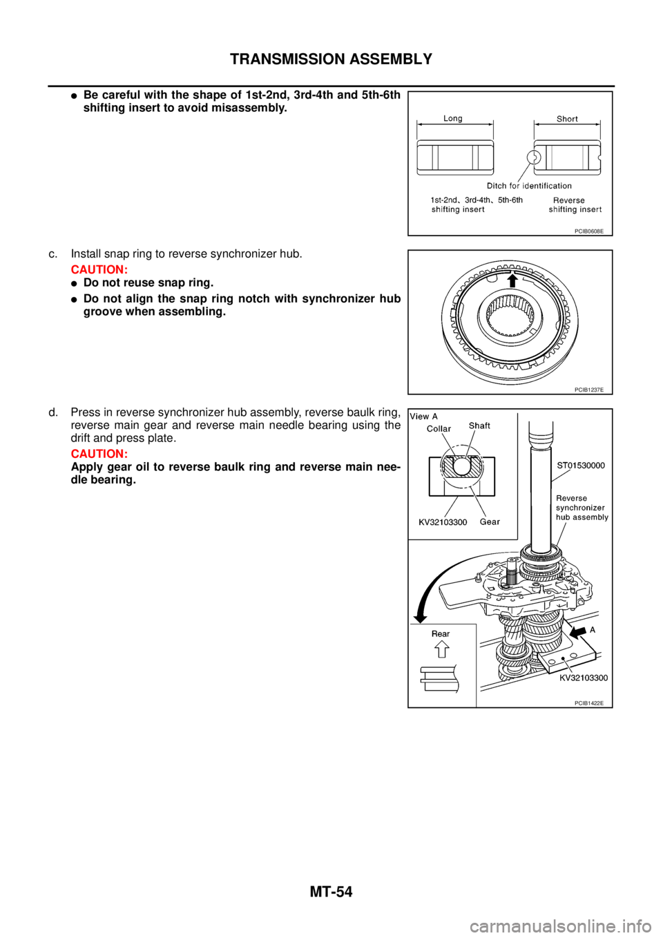
lBe careful with the shape of 1st-2nd, 3rd-4th and 5th-6th
shifting insert to avoid misassembly.
c. Install snap ring to reverse synchronizer hub.
CAUTION:
lDo not reuse snap ring.
lDo not align the snap ring notch with synchronizer hub
groove when assembling.
d. Press in reverse synchronizer hub assembly, reverse baulk ring,
reverse main gear and reverse main needle bearing using the
drift and press plate.
CAUTION:
Apply gear oil to reverse baulk ring and reverse main nee-
dle bearing.
PCIB0608E
PCIB1237E
PCIB1422E
Page 2372 of 3171
TRANSMISSION ASSEMBLY
MT-55
D
E
F
G
H
I
J
K
L
MA
B
MT
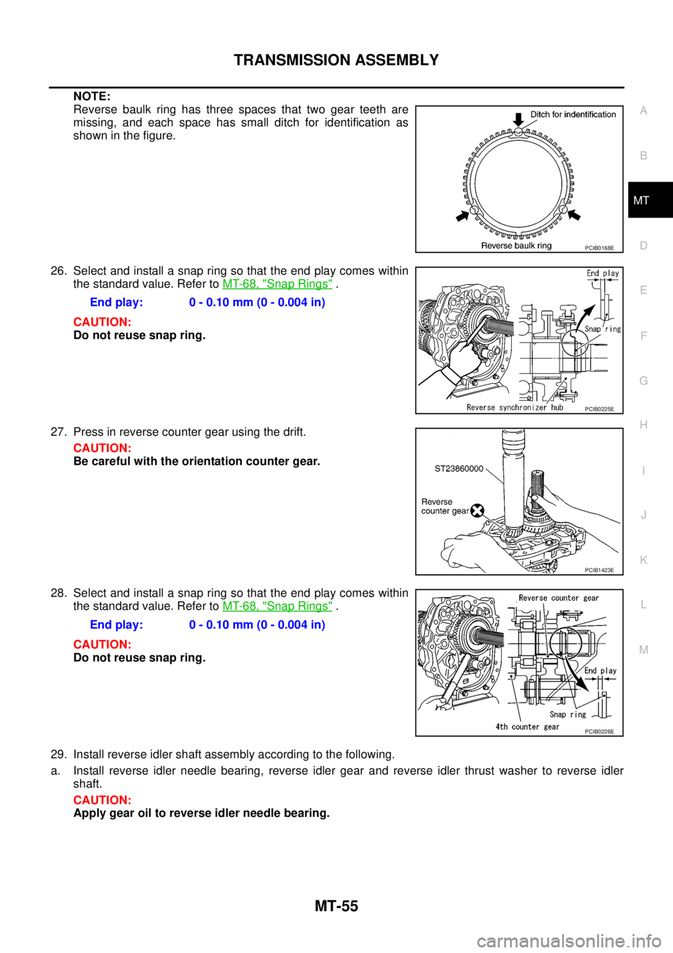
NOTE:
Reverse baulk ring has three spaces that two gear teeth are
missing, and each space has small ditch for identification as
showninthefigure.
26. Select and install a snap ring so that the end play comes within
the standard value. Refer toMT-68, "
Snap Rings".
CAUTION:
Do not reuse snap ring.
27. Press in reverse counter gear using the drift.
CAUTION:
Be careful with the orientation counter gear.
28. Select and install a snap ring so that the end play comes within
the standard value. Refer toMT-68, "
Snap Rings".
CAUTION:
Do not reuse snap ring.
29. Install reverse idler shaft assembly according to the following.
a. Install reverse idler needle bearing, reverse idler gear and reverse idler thrust washer to reverse idler
shaft.
CAUTION:
Apply gear oil to reverse idler needle bearing.
PCIB0168E
End play: 0 - 0.10 mm (0 - 0.004 in)
PCIB0225E
PCIB1423E
End play: 0 - 0.10 mm (0 - 0.004 in)
PCIB0226E
Page 2373 of 3171
MT-56
TRANSMISSION ASSEMBLY
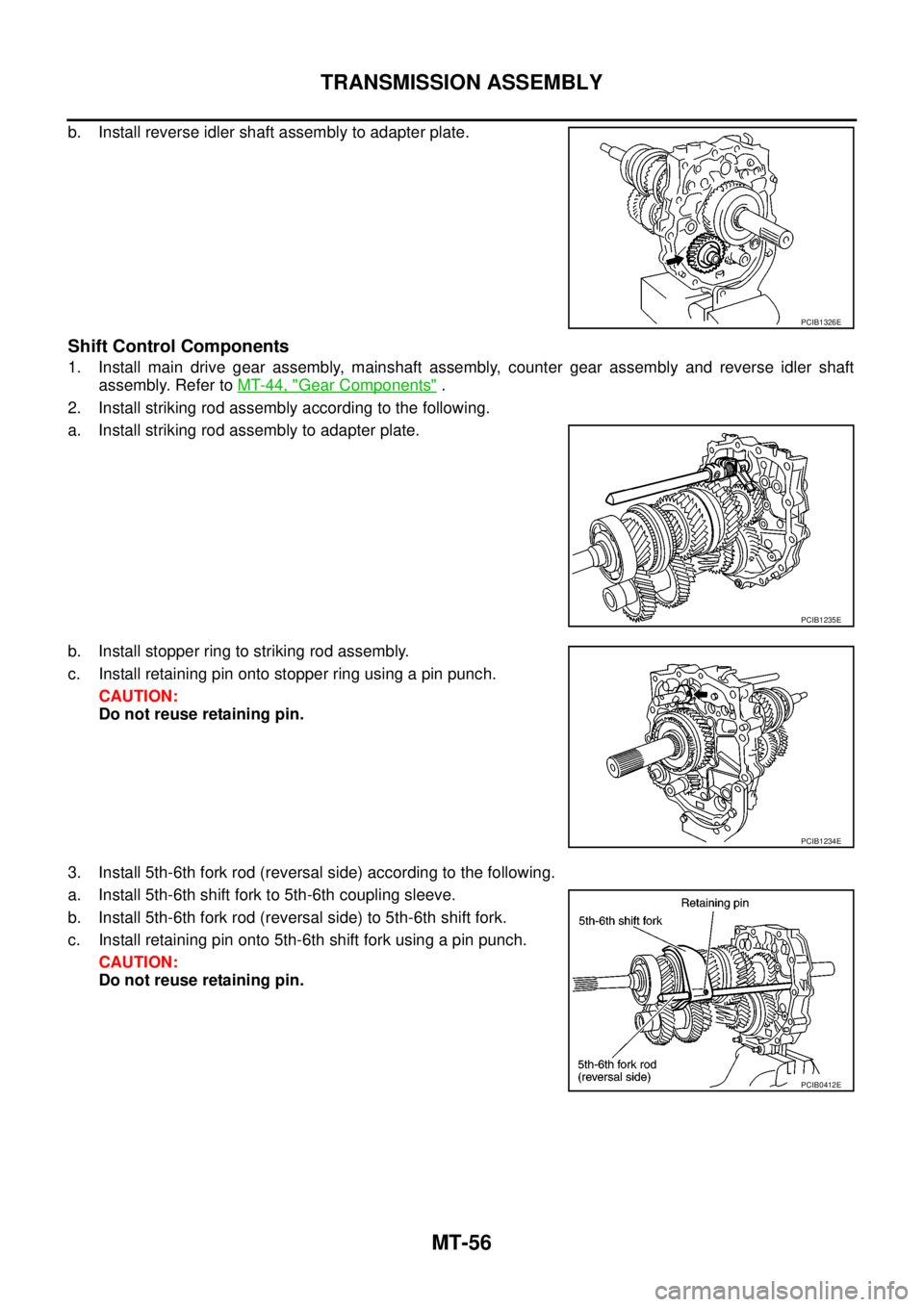
b. Install reverse idler shaft assembly to adapter plate.
Shift Control Components
1. Install main drive gear assembly, mainshaft assembly, counter gear assembly and reverse idler shaft
assembly. Refer toMT-44, "
Gear Components".
2. Install striking rod assembly according to the following.
a. Install striking rod assembly to adapter plate.
b. Install stopper ring to striking rod assembly.
c. Install retaining pin onto stopper ring using a pin punch.
CAUTION:
Do not reuse retaining pin.
3. Install 5th-6th fork rod (reversal side) according to the following.
a. Install 5th-6th shift fork to 5th-6th coupling sleeve.
b. Install 5th-6th fork rod (reversal side) to 5th-6th shift fork.
c. Install retaining pin onto 5th-6th shift fork using a pin punch.
CAUTION:
Do not reuse retaining pin.
PCIB1326E
PCIB1235E
PCIB1234E
PCIB0412E