height adjustment NISSAN NAVARA 2005 Repair User Guide
[x] Cancel search | Manufacturer: NISSAN, Model Year: 2005, Model line: NAVARA, Model: NISSAN NAVARA 2005Pages: 3171, PDF Size: 49.59 MB
Page 2168 of 3171
FRONT FOG LAMP
LT-85
C
D
E
F
G
H
I
J
L
MA
B
LT
Aiming AdjustmentEKS00P4D
The fog lamp is a semi-sealed beam type which uses a replaceable halogen bulb. Before performing aiming
adjustment, make sure of the following.
lKeep all tires inflated to correct pressure.
lPlace vehicle on level surface.
lSee that vehicle is unloaded (except for full levels of coolant, engine oil and fuel, and spare tire, jack, and
tools). Have the driver or equivalent weight placed in driver's seat.
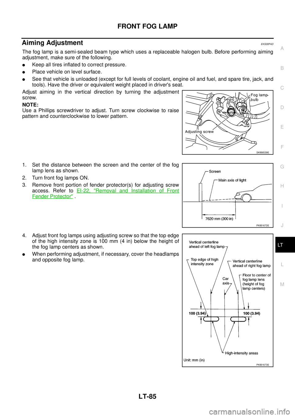
Adjust aiming in the vertical direction by turning the adjustment
screw.
NOTE:
Use a Phillips screwdriver to adjust. Turn screw clockwise to raise
pattern and counterclockwise to lower pattern.
1. Set the distance between the screen and the center of the fog
lamp lens as shown.
2. Turn front fog lamps ON.
3. Remove front portion of fender protector(s) for adjusting screw
access. Refer toEI-22, "
Removal and Installation of Front
Fender Protector".
4. Adjust front fog lamps using adjusting screw so that the top edge
of the high intensity zone is 100 mm (4 in) below the height of
the fog lamp centers as shown.
lWhen performing adjustment, if necessary, cover the headlamps
and opposite fog lamp.
SKIB6539E
PKIB1672E
PKIB1673E
Page 2678 of 3171

RF-1
ROOF
IBODY
CONTENTS
C
D
E
F
G
H
J
K
L
M
SECTIONRF
A
B
RF
ROOF
PRECAUTIONS .......................................................... 2
Precautions for Supplemental Restraint System
(SRS)“AIRBAG”and“SEATBELTPRE-TEN-
SIONER” .................................................................. 2
Precautions .............................................................. 2
PREPARATION ........................................................... 3
Commercial Service Tool ......................................... 3
SQUEAK AND RATTLE TROUBLE DIAGNOSES..... 4
Work Flow ................................................................ 4
CUSTOMER INTERVIEW ..................................... 4
DUPLICATE THE NOISE AND TEST DRIVE ....... 5
CHECK RELATED SERVICE BULLETINS ........... 5
LOCATE THE NOISE AND IDENTIFY THE
ROOT CAUSE ...................................................... 5
REPAIR THE CAUSE ........................................... 5
CONFIRM THE REPAIR ....................................... 6
Generic Squeak and Rattle Troubleshooting ........... 6
INSTRUMENT PANEL .......................................... 6
CENTER CONSOLE ............................................. 6
DOORS ................................................................. 6
TRUNK .................................................................. 7
SUNROOF/HEADLINING ..................................... 7
SEATS ................................................................... 7
UNDERHOOD ....................................................... 7
Diagnostic Worksheet .............................................. 8
SUNROOF ................................................................ 10
Component Parts and Harness Connector Location... 10
System Description ................................................. 11
TILT UP / SLIDE CLOSE OPERATION ................ 11
TILT DOWN / SLIDE OPEN OPERATION ........... 11AUTO OPERATION ............................................. 11
ANTI-PINCH FUNCTION .................................... 11
MEMORY RESET PROCEDURE ....................... 12
INITIALIZATION PROCEDURE .......................... 12
CAN Communication System Description .............. 13
CAN Communication Unit ....................................... 13
Wiring Diagram — SROOF — ................................ 14
Terminals and Reference Value for BCM ............... 15
Terminals and Reference Value for Sunroof Motor
Assembly ................................................................ 15
Work Flow ............................................................... 16
Trouble Diagnosis Symptom Chart ......................... 16
BCM Power Supply and Ground Circuit Check ...... 16
Sunroof Motor Assembly Power Supply and Ground
Circuit Check .......................................................... 17
Sunroof Switch System Check ............................... 18
Fitting Adjustment ................................................... 20
GAP ADJUSTMENT ............................................ 20
HEIGHT DIFFERENCE ADJUSTMENT .............. 20
Removal and Installation ........................................ 21
SUNROOF UNIT ................................................. 22
GLASS LID .......................................................... 22
WIND DEFLECTOR ............................................ 23
SUNSHADE ........................................................ 23
SUNROOF MOTOR ............................................ 23
DRAIN HOSES .................................................... 25
WEATHERSTRIP ................................................ 25
REAR DRAIN ASSEMBLY .................................. 25
LINK AND WIRE ASSEMBLY ............................. 26
Page 2697 of 3171
RF-20
SUNROOF
Fitting Adjustment
EIS00C0M
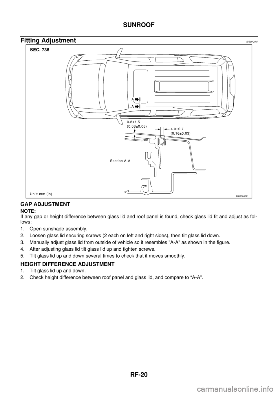
GAP ADJUSTMENT
NOTE:
If any gap or height difference between glass lid and roof panel is found, check glass lid fit and adjust as fol-
lows:
1. Open sunshade assembly.
2. Loosen glass lid securing screws (2 each on left and right sides), then tilt glass lid down.
3. Manually adjust glass lid from outside of vehicle so it resembles "A-A" as shown in the figure.
4. After adjusting glass lid tilt glass lid up and tighten screws.
5. Tilt glass lid up and down several times to check that it moves smoothly.
HEIGHT DIFFERENCE ADJUSTMENT
1. Tilt glass lid up and down.
2. Check height difference between roof panel and glass lid, and compare to “A-A”.
MIIB0883E
Page 2726 of 3171
![NISSAN NAVARA 2005 Repair User Guide REAR FINAL DRIVE ASSEMBLY
RFD-23
[WITH LIMITED SLIP DIFFERENTIAL]
C
E
F
G
H
I
J
K
L
MA
B
RFD
SELECTION ADJUSTING WASHERS
Drive Pinion Height Adjusting Washer
lDrive gear and drive pinion are supplied](/img/5/57362/w960_57362-2725.png "NISSAN NAVARA 2005 Repair User Guide REAR FINAL DRIVE ASSEMBLY
RFD-23
[WITH LIMITED SLIP DIFFERENTIAL]
C
E
F
G
H
I
J
K
L
MA
B
RFD
SELECTION ADJUSTING WASHERS
Drive Pinion Height Adjusting Washer
lDrive gear and drive pinion are supplied")
REAR FINAL DRIVE ASSEMBLY
RFD-23
[WITH LIMITED SLIP DIFFERENTIAL]
C
E
F
G
H
I
J
K
L
MA
B
RFD
SELECTION ADJUSTING WASHERS
Drive Pinion Height Adjusting Washer
lDrive gear and drive pinion are supplied in matched sets only.
Matching numbers on both drive pinion and drive gear are
etched for verification. If a new hypoid gear set is being used,
verify the numbers of each drive pinion and drive gear before
proceeding with assembly.
lThe mounting distance from the center line of drive gear to the back face of drive pinion for the M226 final
drive is 109.5 mm (4.312 in).
On the button end of each drive pinion, there is etched a plus (+) number, a minus (-) number, or a zero
(0), which indicates the best running position for each particular hypoid gear set. This dimension is con-
trolled by a selective drive pinion height adjusting washer between drive pinion rear bearing inner race
and drive pinion.
For example: If a drive pinion is etched m+8 (+3), it would require 0.08 mm (0.003 in) less drive pinion
height adjusting washer than a drive pinion etched “0”. This means decreasing drive pinion height adjust-
ing washer thickness; increases the mounting distance of drive pinion to 109.6 mm (4.315 in). If a drive
pinion is etched m-8 (-3), it would require adding 0.08 mm (0.003 in) more to drive pinion height adjusting
washer than would be required if drive pinion were etched “0”. By adding 0.08 mm (0.003 in), the mount-
ing distance of drive pinion was decreased to 109.4 mm (4.309 in) which is just what a m-8 (-3) etching
indicated.
lTo change drive pinion adjustment, use different drive pinion height adjusting washer which come in differ-
ent thickness.
lUse the following tables as a guide for selecting the correct drive pinion height adjusting washer thickness
to add or subtract from the old drive pinion height adjusting washer.
Unit: mm (in)
SDIA2241E
OLD DRIVE
PINION
MARKINGNEW DRIVE PINION MARKING
-10
(-4)-8
(-3)-5
(-2)-3
(-1)0+3
(+1)+5
(+2)+8
(+3)+10
(+4)
+10
(+4)+0.20
(+0.008)+0.18
(+0.007)+0.15
(+0.006)+0.13
(+0.005)+0.10
(+0.004)+0.08
(+0.003)+0.05
(+0.002)+0.02
(+0.001)0
(0)
+8
(+3)+0.18
(+0.007)+0.15
(+0.006)+0.13
(+0.005)+0.10
(+0.004)+0.08
(+0.003)+0.05
(+0.002)+0.02
(+0.001)0
(0)-0.02
(-0.001)
+5
(+2)+0.15
(+0.006)+0.13
(+0.005)+0.10
(+0.004)+0.08
(+0.003)+0.05
(+0.002)+0.02
(+0.001)0
(0)-0.02
(-0.001)-0.05
(-0.002)
+3
(+1)+0.13
(+0.005)+0.10
(+0.004)+0.08
(+0.003)+0.05
(+0.002)+0.02
(+0.001)0
(0)-0.02
(-0.001)-0.05
(-0.002)-0.08
(-0.003)
0+0.10
(+0.004)+0.08
(+0.003)+0.05
(+0.002)+0.02
(+0.001)0
(0)-0.02
(-0.001)-0.05
(-0.002)-0.08
(-0.003)-0.10
(-0.004)
-3
(-1)+0.08
(+0.003)+0.05
(+0.002)+0.02
(+0.001)0
(0)-0.02
(-0.001)-0.05
(-0.002)-0.08
(-0.003)-0.10
(-0.004)-0.13
(-0.005)
-5
(-2)+0.05
(+0.002)+0.02
(+0.001)0
(0)-0.02
(-0.001)-0.05
(-0.002)-0.08
(-0.003)-0.10
(-0.004)-0.13
(-0.005)-0.15
(-0.006)
-8
(-3)+0.02
(+0.001)0
(0)-0.02
(-0.001)-0.05
(-0.002)-0.08
(-0.003)-0.10
(-0.004)-0.13
(-0.005)-0.15
(-0.006)-0.18
(-0.007)
-10
(-4)0
(0)-0.02
(-0.001)-0.05
(-0.002)-0.08
(-0.003)-0.10
(-0.004)-0.13
(-0.005)-0.15
(-0.006)-0.18
(-0.007)-0.20
(-0.008)
Page 2793 of 3171
![NISSAN NAVARA 2005 Repair User Guide RFD-90
[WITH ELECTRONIC LOCKING DIFFERENTIAL]
REAR FINAL DRIVE ASSEMBLY
INSPECTION AFTER DISASSEMBLY
Drive Gear and Drive Pinion
lIf the gear teeth do not mesh or line-up correctly, determine the caus](/img/5/57362/w960_57362-2792.png "NISSAN NAVARA 2005 Repair User Guide RFD-90
[WITH ELECTRONIC LOCKING DIFFERENTIAL]
REAR FINAL DRIVE ASSEMBLY
INSPECTION AFTER DISASSEMBLY
Drive Gear and Drive Pinion
lIf the gear teeth do not mesh or line-up correctly, determine the caus")
RFD-90
[WITH ELECTRONIC LOCKING DIFFERENTIAL]
REAR FINAL DRIVE ASSEMBLY
INSPECTION AFTER DISASSEMBLY
Drive Gear and Drive Pinion
lIf the gear teeth do not mesh or line-up correctly, determine the cause and adjust, repair, or replace as
necessary.
lIf the gears are worn, cracked, damaged, pitted or chipped (by friction) noticeably, replace with new gears.
lDrive gear and drive pinion are supplied in matched sets only. Matching numbers on both drive pinion and
drive gear are etched for verification. If a new gear set is being used, verify the numbers of each drive pin-
ion and drive gear before proceeding with assembly.
Bearing
lIf bearings are chipped (by friction), pitted, worn, rusted, scratched, or unusual noise is coming from bear-
ing, replace with new bearing assembly (as a new set).
lBearing must be replaced with a new one whenever disassembled.
Differential Case Assembly
lIf the gears are worn, cracked, damaged, pitted or chipped (by friction) noticeably, replace with new differ-
ential case assembly.
lIf the movement is not smooth when pushing cam ring of differential case assembly by hand, repair or
replace as necessary.
Differential Lock Solenoid
lIf the operating part of differential lock solenoid is not smooth, perform component inspection. Refer to
RFD-68, "
COMPONENT INSPECTION".
SELECTION ADJUSTING WASHERS
Drive Pinion Height Adjusting Washer
lDrive gear and drive pinion are supplied in matched sets only.
Matching numbers on both drive pinion and drive gear are
etched for verification. If a new hypoid gear set is being used,
verify the numbers of each drive pinion and drive gear before
proceeding with assembly.
lThe mounting distance from the center line of drive gear to the back face of drive pinion for the M226 final
drive is 109.5 mm (4.312 in).
On the button end of each drive pinion, there is etched a plus (+) number, a minus (-) number, or a zero
(0), which indicates the best running position for each particular hypoid gear set. This dimension is con-
trolled by a selective drive pinion height adjusting washer between drive pinion rear bearing inner race
and drive pinion.
For example: If a drive pinion is etched m+8 (+3), it would require 0.08 mm (0.003 in) less drive pinion
height adjusting washer than a drive pinion etched “0”. This means decreasing drive pinion height adjust-
ing washer thickness; increases the mounting distance of drive pinion to 109.6 mm (4.315 in). If a drive
pinion is etched m-8 (-3), it would require adding 0.08 mm (0.003 in) more to drive pinion height adjusting
washer than would be required if drive pinion were etched “0”. By adding 0.08 mm (0.003 in), the mount-
ing distance of drive pinion was decreased to 109.4 mm (4.309 in) which is just what a m-8 (-3) etching
indicated.
lTo change drive pinion adjustment, use different drive pinion height adjusting washer which come in differ-
ent thickness.
lUse the following tables as a guide for selecting the correct drive pinion height adjusting washer thickness
to add or subtract from the old drive pinion height adjusting washer.
SDIA2241E
Page 2869 of 3171
SC-36
STARTING SYSTEM
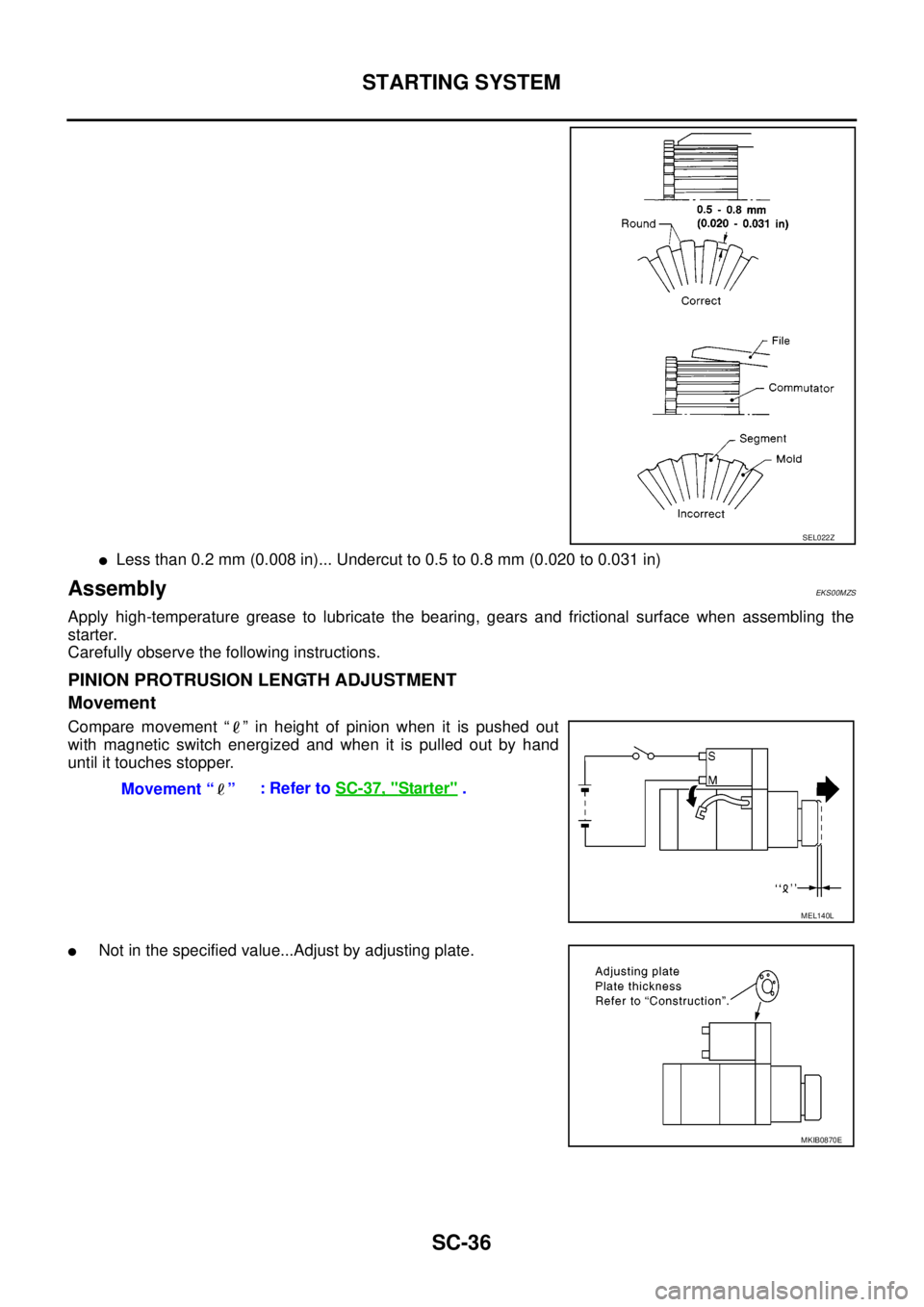
lLess than 0.2 mm (0.008 in)... Undercut to 0.5 to 0.8 mm (0.020 to 0.031 in)
AssemblyEKS00MZS
Apply high-temperature grease to lubricate the bearing, gears and frictional surface when assembling the
starter.
Carefully observe the following instructions.
PINION PROTRUSION LENGTH ADJUSTMENT
Movement
Compare movement “ ” in height of pinion when it is pushed out
with magnetic switch energized and when it is pulled out by hand
until it touches stopper.
lNot in the specified value...Adjust by adjusting plate.
SEL022Z
Movement “ ”:RefertoSC-37, "Starter".
MEL140L
MKIB0870E