engine oil NISSAN NAVARA 2005 Repair Workshop Manual
[x] Cancel search | Manufacturer: NISSAN, Model Year: 2005, Model line: NAVARA, Model: NISSAN NAVARA 2005Pages: 3171, PDF Size: 49.59 MB
Page 2665 of 3171
![NISSAN NAVARA 2005 Repair Workshop Manual RAX-2
[M226]
PRECAUTIONS
[M226]PRECAUTIONSPFP:00001
PrecautionsEDS003HT
lWhen installing the rubber bushings, the final tightening must be done under unladen condition and with
the tires on level grou NISSAN NAVARA 2005 Repair Workshop Manual RAX-2
[M226]
PRECAUTIONS
[M226]PRECAUTIONSPFP:00001
PrecautionsEDS003HT
lWhen installing the rubber bushings, the final tightening must be done under unladen condition and with
the tires on level grou](/img/5/57362/w960_57362-2664.png)
RAX-2
[M226]
PRECAUTIONS
[M226]PRECAUTIONSPFP:00001
PrecautionsEDS003HT
lWhen installing the rubber bushings, the final tightening must be done under unladen condition and with
the tires on level ground. Oil will shorten the life of the rubber bushings, so wipe off any spilled oil immedi-
ately.
lUnladen condition means the fuel tank, engine coolant and lubricants are at the full secification. The
spare tire, jack, hand tools, and mats are in their designated positions.
lLock nuts are not reusable. Always use new lock nuts for installation. New lock nuts are pre-oiled, do not
apply any additional lubrication.
Page 2706 of 3171
![NISSAN NAVARA 2005 Repair Workshop Manual PRECAUTIONS
RFD-3
[WITH LIMITED SLIP DIFFERENTIAL]
C
E
F
G
H
I
J
K
L
MA
B
RFD
[WITH LIMITED SLIP DIFFERENTIAL]PRECAUTIONSPFP:00001
Limited Slip Differential (LSD) Performance JudgementEDS003IG
lInspec NISSAN NAVARA 2005 Repair Workshop Manual PRECAUTIONS
RFD-3
[WITH LIMITED SLIP DIFFERENTIAL]
C
E
F
G
H
I
J
K
L
MA
B
RFD
[WITH LIMITED SLIP DIFFERENTIAL]PRECAUTIONSPFP:00001
Limited Slip Differential (LSD) Performance JudgementEDS003IG
lInspec](/img/5/57362/w960_57362-2705.png)
PRECAUTIONS
RFD-3
[WITH LIMITED SLIP DIFFERENTIAL]
C
E
F
G
H
I
J
K
L
MA
B
RFD
[WITH LIMITED SLIP DIFFERENTIAL]PRECAUTIONSPFP:00001
Limited Slip Differential (LSD) Performance JudgementEDS003IG
lInspection is required when detecting any noise or malfunction while driving or turning. Improper condition
of oil or differential case assembly is suspected. Refer toRFD-3, "
METHOD FOR TROUBLESHOOTING"
.
METHOD FOR TROUBLESHOOTING
1. Check differential gear oil level and differential gear oil leakage. Refer toRFD-9, "Checking Differential
Gear Oil".
2. Changing differential gear oil. Refer toRFD-9, "
Changing Differential Gear Oil".
3. Start engine. Drive for 10 min.
4. Again changing differential gear oil. Refer toRFD-9, "
Changing Differential Gear Oil".
5. Start engine. Drive for 10 min. Check if any noise or improper oil condition is detected.
lIf OK, check differential gear oil level and differential gear oil leakage. Refer toRFD-9, "Checking Differ-
ential Gear Oil".
lIf NG, replace differential case assembly after checking each part of final drive. Refer toRFD-15, "Dis-
assembly and Assembly".
Service Notice or PrecautionsEDS0038Z
lCheck for the correct installation status prior to removal or disassembly. If matching marks are required,
be certain they do not interfere with the function of the parts when applied.
lOverhaul should be done in a clean work area, it is preferable to work in dust proof area.
lBefore disassembly completely remove sand and mud from the exterior of the unit, preventing them from
entering into the unit during disassembly or assembly.
lCheck appearance of the disassembled parts for damage, deformation, and unusual wear. Replace them
with new ones if necessary.
lGaskets, seals and O-rings should be replaced any time the unit is disassembled.
lIn principle, tighten bolts or nuts gradually in several steps working diagonally from inside to outside. If
tightening sequence is specified, observe it.
lClean and flush the parts sufficiently and blow-dry them.
lBe careful not to damage sliding surfaces and mating surfaces.
lWhen applying sealant, remove the old sealant from the mounting surface; then remove any moisture, oil,
and foreign materials from the application and mounting surfaces.
lAlways use shop paper for cleaning the inside of components.
lAvoid using cotton gloves or shop rags to prevent entering of lint.
lDuring assembly, observe the specified tightening torque, and apply new differential gear oil, petroleum
jelly, or multi-purpose grease as specified.
Page 2712 of 3171
![NISSAN NAVARA 2005 Repair Workshop Manual DIFFERENTIAL GEAR OIL
RFD-9
[WITH LIMITED SLIP DIFFERENTIAL]
C
E
F
G
H
I
J
K
L
MA
B
RFD
DIFFERENTIAL GEAR OILPFP:KLD30
Changing Differential Gear OilEDS00394
DRAINING
1. Stop engine.
2. Remove drain p NISSAN NAVARA 2005 Repair Workshop Manual DIFFERENTIAL GEAR OIL
RFD-9
[WITH LIMITED SLIP DIFFERENTIAL]
C
E
F
G
H
I
J
K
L
MA
B
RFD
DIFFERENTIAL GEAR OILPFP:KLD30
Changing Differential Gear OilEDS00394
DRAINING
1. Stop engine.
2. Remove drain p](/img/5/57362/w960_57362-2711.png)
DIFFERENTIAL GEAR OIL
RFD-9
[WITH LIMITED SLIP DIFFERENTIAL]
C
E
F
G
H
I
J
K
L
MA
B
RFD
DIFFERENTIAL GEAR OILPFP:KLD30
Changing Differential Gear OilEDS00394
DRAINING
1. Stop engine.
2. Remove drain plug and drain gear oil.
3. Apply sealant to drain plug. Install drain plug to final drive
assembly and tighten to the specified torque. Refer toRFD-15,
"COMPONENTS".
FILLING
1. Remove filler plug. Fill with new gear oil until oil level reaches
the specified limit near filler plug hole.
2. After refilling oil, check oil level. Apply sealant to filler plug.
Install filler plug to final drive assembly and tighten to the speci-
fied torque. Refer toRFD-15, "
COMPONENTS".
Checking Differential Gear OilEDS00395
OIL LEAKAGE AND OIL LEVEL
1. Make sure that gear oil is not leaking from final drive assembly or around it.
2. Check oil level from filler plug hole as shown.
CAUTION:
Do not start engine while checking oil level.
3. Apply sealant to filler plug. Install filler plug to final drive assem-
bly and tighten to the specified torque. Refer toRFD-15, "
COM-
PONENTS".
PDIA1038E
OilgradeandViscosity:
Refer toMA-14, "
Fluids and Lubricants".
Oil capacity:
Approx. 2.01 (3-1/2pt)
PDIA1039E
PDIA1039E
Page 2743 of 3171
![NISSAN NAVARA 2005 Repair Workshop Manual RFD-40
[WITH ELECTRONIC LOCKING DIFFERENTIAL]
DIFFERENTIAL GEAR OIL
DIFFERENTIAL GEAR OIL
PFP:KLD30
Changing Differential Gear OilEDS003AN
DRAINING
1. Stop engine.
2. Remove drain plug and drain gear NISSAN NAVARA 2005 Repair Workshop Manual RFD-40
[WITH ELECTRONIC LOCKING DIFFERENTIAL]
DIFFERENTIAL GEAR OIL
DIFFERENTIAL GEAR OIL
PFP:KLD30
Changing Differential Gear OilEDS003AN
DRAINING
1. Stop engine.
2. Remove drain plug and drain gear](/img/5/57362/w960_57362-2742.png)
RFD-40
[WITH ELECTRONIC LOCKING DIFFERENTIAL]
DIFFERENTIAL GEAR OIL
DIFFERENTIAL GEAR OIL
PFP:KLD30
Changing Differential Gear OilEDS003AN
DRAINING
1. Stop engine.
2. Remove drain plug and drain gear oil.
3. Apply sealant to drain plug. Install drain plug to final drive
assembly and tighten to the specified torque. Refer toRFD-82,
"COMPONENTS".
FILLING
1. Remove filler plug. Fill with new gear oil until oil level reaches
the specified limit near filler plug hole.
2. After refilling oil, check oil level. Apply sealant to filler plug.
Install filler plug to final drive assembly and tighten to the speci-
fied torque. Refer toRFD-82, "
COMPONENTS".
Checking Differential Gear OilEDS003AO
OIL LEAKAGE AND OIL LEVEL
1. Make sure that gear oil is not leaking from final drive assembly or around it.
2. Check oil level from filler plug hole as shown.
CAUTION:
Do not start engine while checking oil level.
3. Apply sealant to filler plug. Install filler plug to final drive assem-
bly and tighten to the specified torque. Refer toRFD-82, "
COM-
PONENTS".
PDIA1038E
Oil grade and Viscosity:
Refer toMA-14, "
Fluids and Lubricants".
Oil capacity:
Approx. 2.01 (3-1/2pt)
PDIA1039E
PDIA1039E
Page 2807 of 3171

RSU-2
PRECAUTIONS
PRECAUTIONS
PFP:00001
PrecautionsEES002JD
lWhen installing rubber parts, final tightening must be carried out under unladen condition* with
tires on ground.
*Fuel, radiator coolant, and engine oil are full. Spare tire, jack, hand tools, and mats are in their
designated positions. Oil will shorten the life of rubber bushings, so wipe off any spilled oil imme-
diately.
lLock nuts are not reusable. Always use new lock nuts for installation. New lock nuts are pre-oiled,
do not apply any additional lubrication.
Page 2810 of 3171
REAR SUSPENSION ASSEMBLY
RSU-5
C
D
F
G
H
I
J
K
L
MA
B
RSU
CAUTION:
When installing the components with rubber bushings, the final tightening of the nuts and bolts must
be done with the vehicle in an unladen condition (the fuel, engine coolant, and engine oil full; the
spare tire, jack, hand tools and mats in their designated positions) with the tires on the ground.
On-Vehicle Inspection and ServiceEES002JH
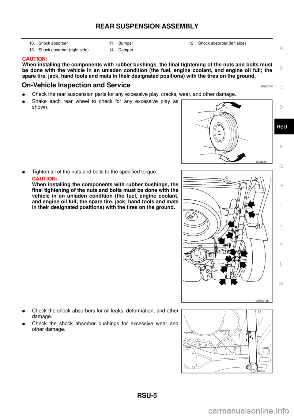
lCheck the rear suspension parts for any excessive play, cracks, wear, and other damage.
lShake each rear wheel to check for any excessive play as
shown.
lTighten all of the nuts and bolts to the specified torque.
CAUTION:
When installing the components with rubber bushings, the
final tightening of the nuts and bolts must be done with the
vehicle in an unladen condition (the fuel, engine coolant,
and engine oil full; the spare tire, jack, hand tools and mats
in their designated positions) with the tires on the ground.
lCheck the shock absorbers for oil leaks, deformation, and other
damage.
lCheck the shock absorber bushings for excessive wear and
other damage.
10. Shock absorber 11. Bumper 12. Shock absorber (left side)
13. Shock absorber (right side) 14. Damper
SMA525A
MEIB9019E
SRA734
Page 2813 of 3171
RSU-8
LEAF SPRING
CAUTION:
When installing the components with rubber bushings, the final tightening of the nuts and bolts must
be done with the vehicle in an unladen condition (the fuel, engine coolant, and engine oil full; the
spare tire, jack, hand tools and mats in their designated positions) with the tires on the ground.
REMOVAL
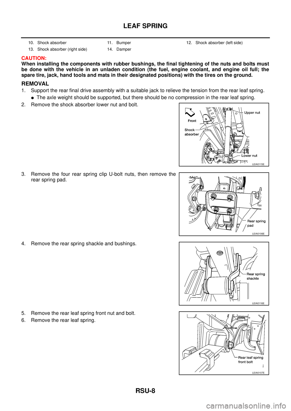
1. Support the rear final drive assembly with a suitable jack to relieve the tension from the rear leaf spring.
lThe axle weight should be supported, but there should be no compression in the rear leaf spring.
2. Remove the shock absorber lower nut and bolt.
3. Remove the four rear spring clip U-bolt nuts, then remove the
rear spring pad.
4. Remove the rear spring shackle and bushings.
5. Remove the rear leaf spring front nut and bolt.
6. Remove the rear leaf spring.
10. Shock absorber 11. Bumper 12. Shock absorber (left side)
13. Shock absorber (right side) 14. Damper
LEIA0115E
LEIA0106E
LEIA0116E
LEIA0107E
Page 2815 of 3171
RSU-10
LEAF SPRING
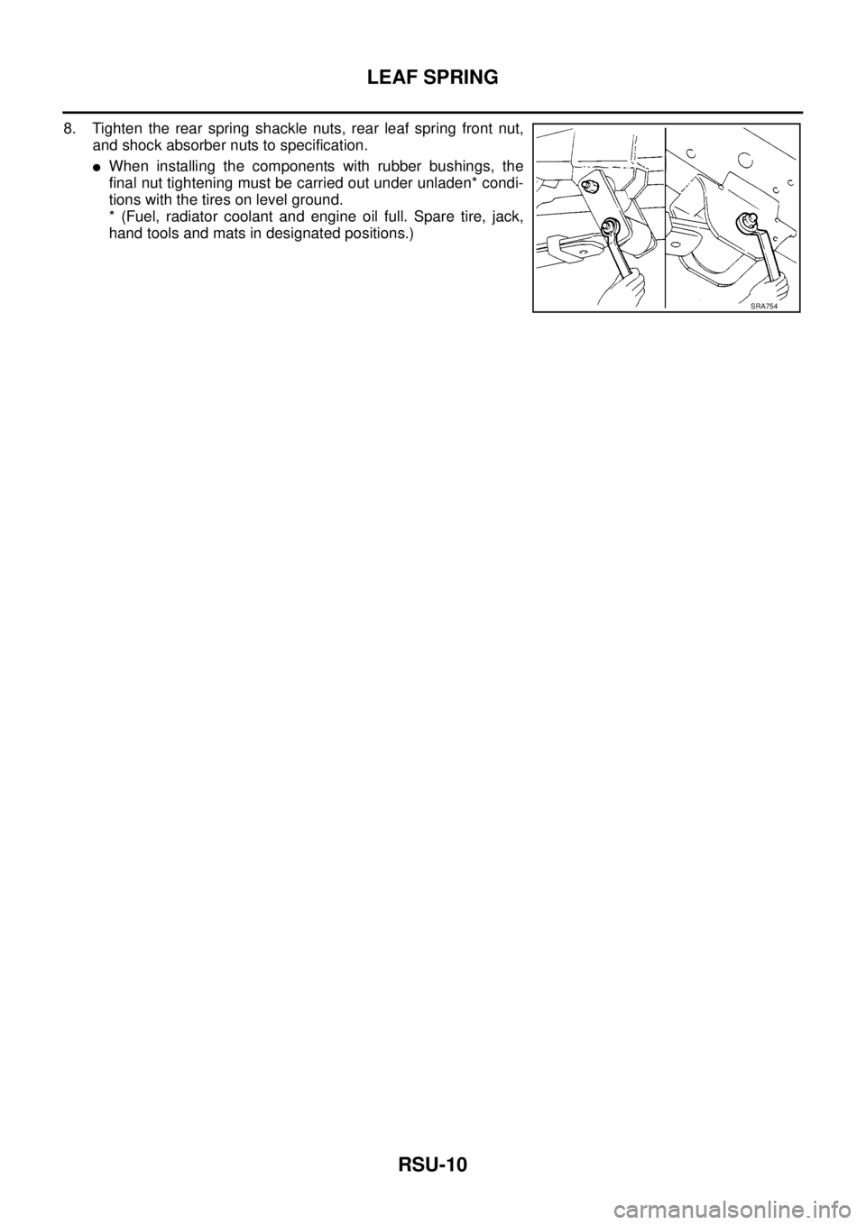
8. Tighten the rear spring shackle nuts, rear leaf spring front nut,
and shock absorber nuts to specification.
lWhen installing the components with rubber bushings, the
final nut tightening must be carried out under unladen* condi-
tions with the tires on level ground.
* (Fuel, radiator coolant and engine oil full. Spare tire, jack,
hand tools and mats in designated positions.)
SRA754
Page 2816 of 3171
SERVICE DATA AND SPECIFICATIONS (SDS)
RSU-11
C
D
F
G
H
I
J
K
L
MA
B
RSU
SERVICE DATA AND SPECIFICATIONS (SDS)PFP:00030
General Specifications (Rear)EES002JK
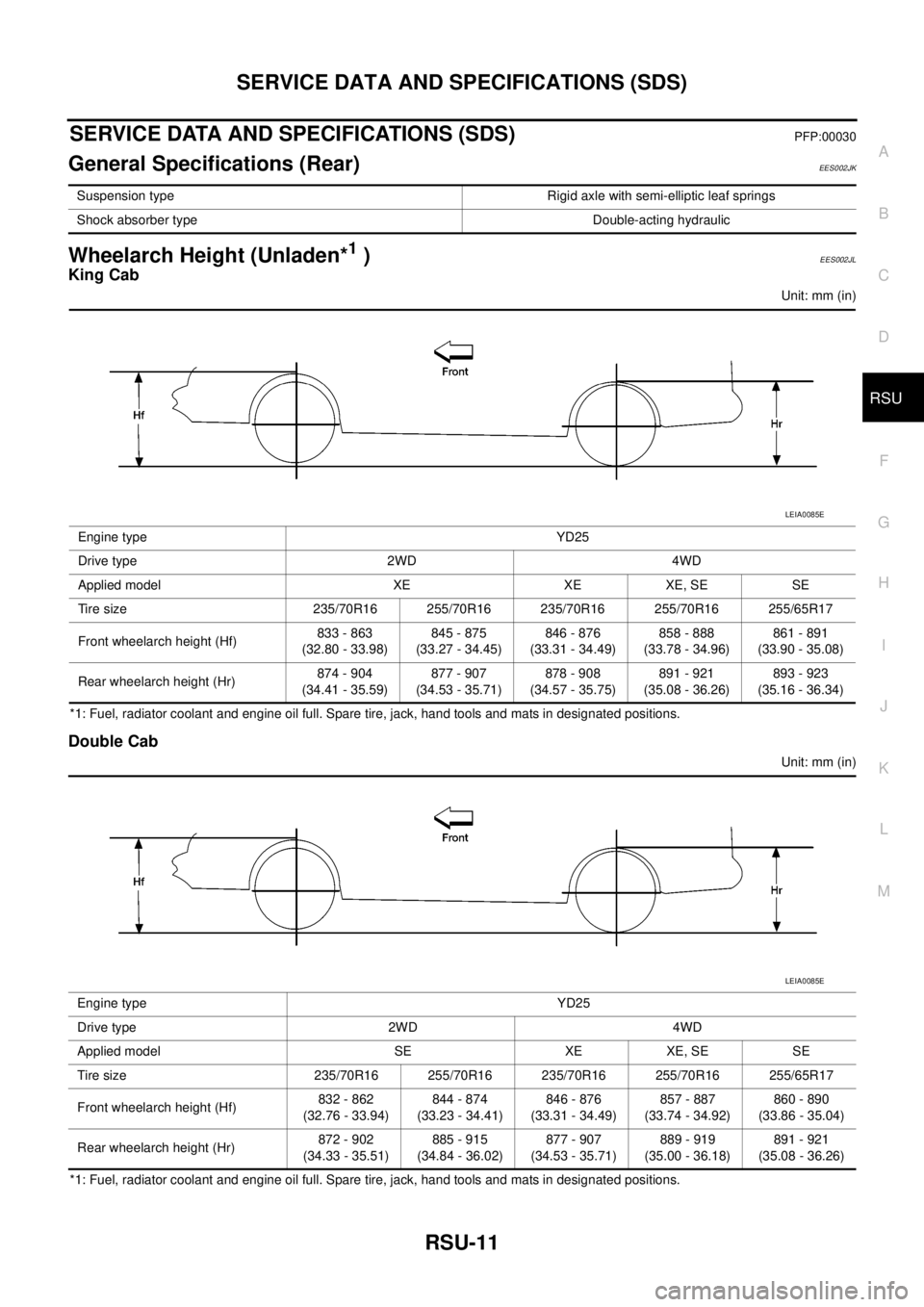
Wheelarch Height (Unladen*1)EES002JL
King Cab
Unit: mm (in)
*1: Fuel, radiator coolant and engine oil full. Spare tire, jack, hand tools and mats in designated positions.
Double Cab
Unit: mm (in)
*1: Fuel, radiator coolant and engine oil full. Spare tire, jack, hand tools and mats in designated positions.Suspension type Rigid axle with semi-elliptic leaf springs
Shock absorber type Double-acting hydraulic
Engine type YD25
Drive type 2WD 4WD
Applied model XE XE XE, SE SE
Tire size 235/70R16 255/70R16 235/70R16 255/70R16 255/65R17
Front wheelarch height (Hf)833 - 863
(32.80 - 33.98)845 - 875
(33.27 - 34.45)846 - 876
(33.31 - 34.49)858 - 888
(33.78 - 34.96)861 - 891
(33.90 - 35.08)
Rear wheelarch height (Hr)874 - 904
(34.41 - 35.59)877 - 907
(34.53 - 35.71)878 - 908
(34.57 - 35.75)891 - 921
(35.08 - 36.26)893 - 923
(35.16 - 36.34)
LEIA0085E
Engine type YD25
Drive type 2WD 4WD
Applied model SE XE XE, SE SE
Tire size 235/70R16 255/70R16 235/70R16 255/70R16 255/65R17
Front wheelarch height (Hf)832 - 862
(32.76 - 33.94)844 - 874
(33.23 - 34.41)846 - 876
(33.31 - 34.49)857 - 887
(33.74 - 34.92)860 - 890
(33.86 - 35.04)
Rear wheelarch height (Hr)872 - 902
(34.33 - 35.51)885 - 915
(34.84 - 36.02)877 - 907
(34.53 - 35.71)889 - 919
(35.00 - 36.18)891 - 921
(35.08 - 36.26)
LEIA0085E
Page 2870 of 3171
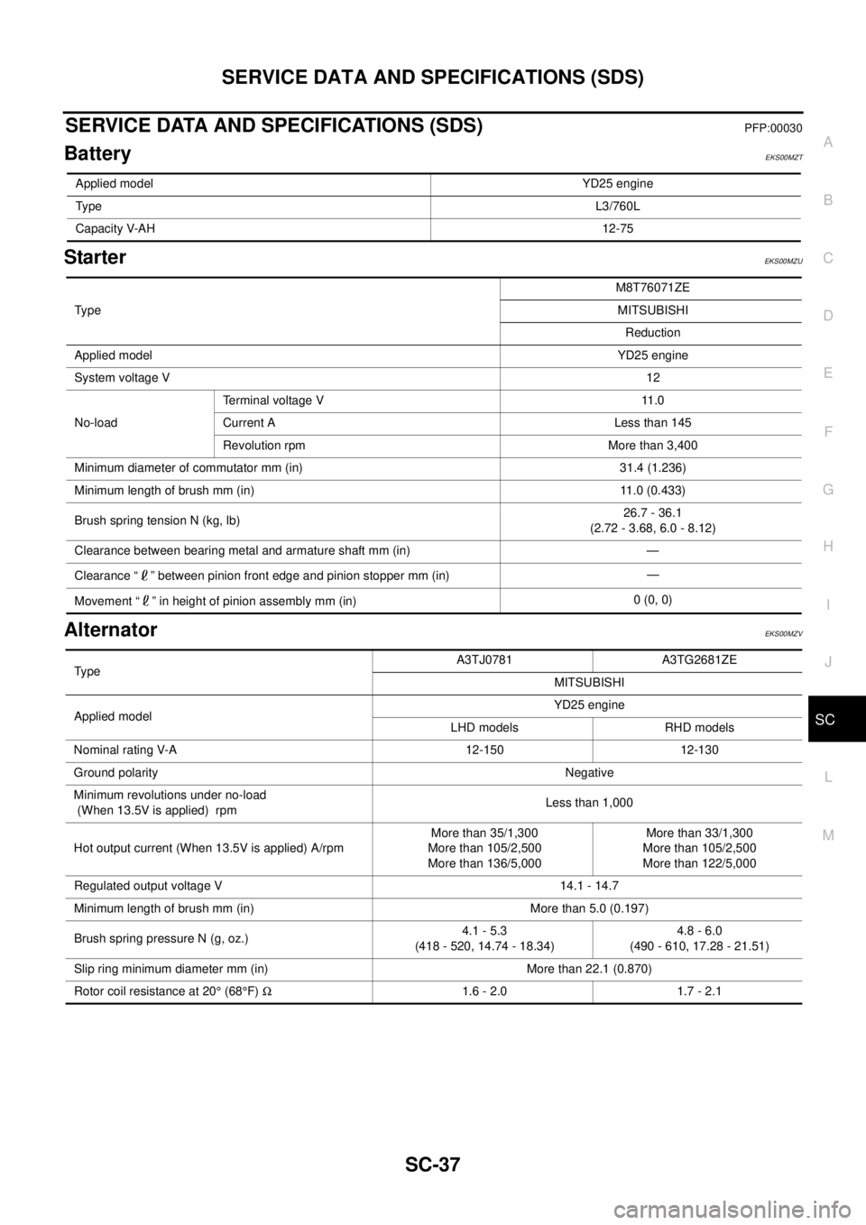
SERVICE DATA AND SPECIFICATIONS (SDS)
SC-37
C
D
E
F
G
H
I
J
L
MA
B
SC
SERVICE DATA AND SPECIFICATIONS (SDS)PFP:00030
BatteryEKS00MZT
StarterEKS00MZU
AlternatorEKS00MZV
Applied modelYD25 engine
TypeL3/760L
Capacity V-AH12-75
Ty p eM8T76071ZE
MITSUBISHI
Reduction
Applied modelYD25 engine
System voltage V12
No-loadTerminal voltage V 11.0
Current A Less than 145
Revolution rpm More than 3,400
Minimum diameter of commutator mm (in) 31.4 (1.236)
Minimum length of brush mm (in) 11.0 (0.433)
Brush spring tension N (kg, lb)26.7 - 36.1
(2.72 - 3.68, 6.0 - 8.12)
Clearance between bearing metal and armature shaft mm (in) —
Clearance “ ” between pinion front edge and pinion stopper mm (in)—
Movement “ ” in height of pinion assembly mm (in)0 (0, 0)
TypeA3TJ0781 A3TG2681ZE
MITSUBISHI
Applied modelYD25 engine
LHD models RHD models
Nominal rating V-A 12-150 12-130
Ground polarityNegative
Minimum revolutions under no-load
(When 13.5V is applied) rpmLess than 1,000
Hot output current (When 13.5V is applied) A/rpmMore than 35/1,300
More than 105/2,500
More than 136/5,000More than 33/1,300
More than 105/2,500
More than 122/5,000
Regulated output voltage V 14.1 - 14.7
Minimum length of brush mm (in) More than 5.0 (0.197)
Brush spring pressure N (g, oz.)4.1 - 5.3
(418 - 520, 14.74 - 18.34)4.8 - 6.0
(490 - 610, 17.28 - 21.51)
Slip ring minimum diameter mm (in) More than 22.1 (0.870)
Rotor coil resistance at 20°(68°F)W1.6 - 2.0 1.7 - 2.1