NISSAN NAVARA 2005 Repair Workshop Manual
Manufacturer: NISSAN, Model Year: 2005, Model line: NAVARA, Model: NISSAN NAVARA 2005Pages: 3171, PDF Size: 49.59 MB
Page 2801 of 3171
![NISSAN NAVARA 2005 Repair Workshop Manual RFD-98
[WITH ELECTRONIC LOCKING DIFFERENTIAL]
REAR FINAL DRIVE ASSEMBLY
11. Apply gear oil to side bearings. Install differential case assembly
with side bearing outer races into axle housing.
12. App NISSAN NAVARA 2005 Repair Workshop Manual RFD-98
[WITH ELECTRONIC LOCKING DIFFERENTIAL]
REAR FINAL DRIVE ASSEMBLY
11. Apply gear oil to side bearings. Install differential case assembly
with side bearing outer races into axle housing.
12. App](/img/5/57362/w960_57362-2800.png)
RFD-98
[WITH ELECTRONIC LOCKING DIFFERENTIAL]
REAR FINAL DRIVE ASSEMBLY
11. Apply gear oil to side bearings. Install differential case assembly
with side bearing outer races into axle housing.
12. Apply multi-purpose grease to sensor connector.
CAUTION:
Do not reuse sensor connector.
13. Connect differential lock solenoid harness and sensor connec-
tor. Then install it to axle housing, tighten to the specified torque.
Refer toRFD-82, "
COMPONENTS".
14. Align paint matching mark on side bearing cap with that on axle
housing and install side bearing caps on axle housing.
CAUTION:
Do not tighten at this point. This allows further tightening of
side bearing adjusters.
15. Tighten each side bearing adjusters using Tool.
16. Adjust backlash of drive gear and drive pinion. Refer toRFD-84,
"Backlash".
17. Check tooth contact. Refer toRFD-83, "
To o t h C o n t a c t".
18. Check total preload. Refer toRFD-83, "
Total Preload Torque".
19. Apply sealant to mating surface of carrier cover. Refer toRFD-
82, "COMPONENTS".
CAUTION:
Remove old sealant adhering to mating surfaces. Also
remove any moisture, oil, or foreign material adhering to
application and mating surfaces.
SDIA2588E
SDIA3456E
SDIA2632E
Tool number : KV38108800
PDIA1044E
PDIA1061E
Page 2802 of 3171
![NISSAN NAVARA 2005 Repair Workshop Manual REAR FINAL DRIVE ASSEMBLY
RFD-99
[WITH ELECTRONIC LOCKING DIFFERENTIAL]
C
E
F
G
H
I
J
K
L
MA
B
RFD
20. Install carrier cover and bracket on axle housing. Then tighten
carrier cover bolts to the specif NISSAN NAVARA 2005 Repair Workshop Manual REAR FINAL DRIVE ASSEMBLY
RFD-99
[WITH ELECTRONIC LOCKING DIFFERENTIAL]
C
E
F
G
H
I
J
K
L
MA
B
RFD
20. Install carrier cover and bracket on axle housing. Then tighten
carrier cover bolts to the specif](/img/5/57362/w960_57362-2801.png)
REAR FINAL DRIVE ASSEMBLY
RFD-99
[WITH ELECTRONIC LOCKING DIFFERENTIAL]
C
E
F
G
H
I
J
K
L
MA
B
RFD
20. Install carrier cover and bracket on axle housing. Then tighten
carrier cover bolts to the specified torque. Refer toRFD-82,
"COMPONENTS".
PDIA1066E
Page 2803 of 3171
![NISSAN NAVARA 2005 Repair Workshop Manual RFD-100
[WITH ELECTRONIC LOCKING DIFFERENTIAL]
SERVICE DATA AND SPECIFICATIONS (SDS)
SERVICE DATA AND SPECIFICATIONS (SDS)
PFP:00030
General SpecificationsEDS003BH
Inspection and AdjustmentEDS003BI
PR NISSAN NAVARA 2005 Repair Workshop Manual RFD-100
[WITH ELECTRONIC LOCKING DIFFERENTIAL]
SERVICE DATA AND SPECIFICATIONS (SDS)
SERVICE DATA AND SPECIFICATIONS (SDS)
PFP:00030
General SpecificationsEDS003BH
Inspection and AdjustmentEDS003BI
PR](/img/5/57362/w960_57362-2802.png)
RFD-100
[WITH ELECTRONIC LOCKING DIFFERENTIAL]
SERVICE DATA AND SPECIFICATIONS (SDS)
SERVICE DATA AND SPECIFICATIONS (SDS)
PFP:00030
General SpecificationsEDS003BH
Inspection and AdjustmentEDS003BI
PRELOAD TORQUE
Unit: N·m (kg-m, in-lb)
BACKLASH
Unit: mm (in)
COMPANION FLANGE RUNOUT
Unit: mm (in) Applied modelYD25DDTi
4WD
5A/T 6M/T
Final drive modelM226
Gear ratio 3.538 3.692
Number of pinion gears 2
Number of teeth (Drive gear / drive pinion) 46/13 48/13
Oil capacity (Approx.)
(lmp pt)2.01 (3-1/2)
Drive pinion adjustment spacer type Collapsible
ItemStandard
Gear ratio: 3.538 type Gear ratio: 3.692 type
Total preload 2.34 - 4.34 (0.24 - 0.44, 21 - 38) 2.32 - 4.34 (0.24 - 0.44, 21 - 38)
Pinion bearing preload 1.7 - 3.1 (0.18 - 0.31, 15 - 27)
Item Standard
Drive gear to drive pinion gear 0.08 - 0.13 (0.0031 - 0.0051)
Item Runout limit
Companion flange face 0.10 (0.0039) or less
Inner side of companion flange 0.13 (0.0051) or less
Page 2804 of 3171
![NISSAN NAVARA 2005 Repair Workshop Manual SERVICE DATA AND SPECIFICATIONS (SDS)
RFD-101
[WITH ELECTRONIC LOCKING DIFFERENTIAL]
C
E
F
G
H
I
J
K
L
MA
B
RFD
SELECTIVE PARTS
Drive Pinion Height Adjusting Washer
Unit: mm (in)
*Always check with th NISSAN NAVARA 2005 Repair Workshop Manual SERVICE DATA AND SPECIFICATIONS (SDS)
RFD-101
[WITH ELECTRONIC LOCKING DIFFERENTIAL]
C
E
F
G
H
I
J
K
L
MA
B
RFD
SELECTIVE PARTS
Drive Pinion Height Adjusting Washer
Unit: mm (in)
*Always check with th](/img/5/57362/w960_57362-2803.png)
SERVICE DATA AND SPECIFICATIONS (SDS)
RFD-101
[WITH ELECTRONIC LOCKING DIFFERENTIAL]
C
E
F
G
H
I
J
K
L
MA
B
RFD
SELECTIVE PARTS
Drive Pinion Height Adjusting Washer
Unit: mm (in)
*Always check with the Parts Department for the latest parts information.Thickness Package part number*
0.076 (0.030)
0.079 (0.031)
0.081 (0.032)
0.084 (0.033)
0.086 (0.034)38151 8S101
0.089 (0.035)
0.091 (0.036)
0.094 (0.037)
0.097 (0.038)
0.099 (0.039)38151 8S102
0.102 (0.040)
0.104 (0.041)
0.107 (0.042)
0.109 (0.043)
0.112 (0.044)38151 8S103
0.114 (0.045)
0.117 (0.046)
0.119 (0.047)
0.122 (0.048)
0.124 (0.049)38151 8S104
0.127 (0.050)
0.130 (0.051)
0.132 (0.052)
0.135 (0.053)
0.137 (0.054)38151 8S105
Page 2805 of 3171
![NISSAN NAVARA 2005 Repair Workshop Manual RFD-102
[WITH ELECTRONIC LOCKING DIFFERENTIAL]
SERVICE DATA AND SPECIFICATIONS (SDS) NISSAN NAVARA 2005 Repair Workshop Manual RFD-102
[WITH ELECTRONIC LOCKING DIFFERENTIAL]
SERVICE DATA AND SPECIFICATIONS (SDS)](/img/5/57362/w960_57362-2804.png)
RFD-102
[WITH ELECTRONIC LOCKING DIFFERENTIAL]
SERVICE DATA AND SPECIFICATIONS (SDS)
Page 2806 of 3171

RSU-1
REAR SUSPENSION
E SUSPENSION
CONTENTS
C
D
F
G
H
I
J
K
L
M
SECTIONRSU
A
B
RSU
REAR SUSPENSION
PRECAUTIONS .......................................................... 2
Precautions .............................................................. 2
NOISE, VIBRATION AND HARSHNESS (NVH)
TROUBLESHOOTING ................................................ 3
NVH Troubleshooting Chart ..................................... 3
REAR SUSPENSION ASSEMBLY ............................. 4
Components ............................................................. 4
On-Vehicle Inspection and Service .......................... 5
SHOCK ABSORBER .................................................. 6
Removal and Installation .......................................... 6
REMOVAL ............................................................. 6
INSPECTION AFTER REMOVAL ......................... 6
INSTALLATION ..................................................... 6LEAF SPRING ............................................................ 7
Removal and Installation .......................................... 7
REMOVAL ............................................................. 8
INSPECTION AFTER REMOVAL ......................... 9
INSTALLATION ..................................................... 9
SERVICE DATA AND SPECIFICATIONS (SDS) ...... 11
General Specifications (Rear) ................................ 11
Wheelarch Height (Unladen*
1) .............................. 11
Page 2807 of 3171

RSU-2
PRECAUTIONS
PRECAUTIONS
PFP:00001
PrecautionsEES002JD
lWhen installing rubber parts, final tightening must be carried out under unladen condition* with
tires on ground.
*Fuel, radiator coolant, and engine oil are full. Spare tire, jack, hand tools, and mats are in their
designated positions. Oil will shorten the life of rubber bushings, so wipe off any spilled oil imme-
diately.
lLock nuts are not reusable. Always use new lock nuts for installation. New lock nuts are pre-oiled,
do not apply any additional lubrication.
Page 2808 of 3171

NOISE, VIBRATION AND HARSHNESS (NVH) TROUBLESHOOTING
RSU-3
C
D
F
G
H
I
J
K
L
MA
B
RSU
NOISE, VIBRATION AND HARSHNESS (NVH) TROUBLESHOOTINGPFP:54000
NVH Troubleshooting ChartEES002JF
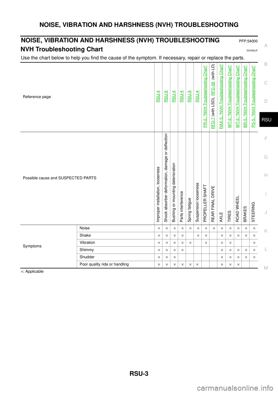
Use the chart below to help you find the cause of the symptom. If necessary, repair or replace the parts.
´: Applicable Reference page
RSU-4RSU-6RSU-4RSU-4RSU-9RSU-4
PR-2, "
NVH Troubleshooting Chart
"
RFD-7
(with LSD),RFD-39
(with LD)
RAX-5, "
NVH Troubleshooting Chart
"
WT-2, "
NVH Troubleshooting Chart
"
WT-2, "
NVH Troubleshooting Chart
"
BR-5, "
NVH Troubleshooting Chart
"
PS-5, "
NVH Troubleshooting Chart
"
Possible cause and SUSPECTED PARTS
Improper installation, looseness
Shock absorber deformation, damage or deflection
Bushing or mounting deterioration
Parts interference
Spring fatigue
Suspension looseness
PROPELLER SHAFT
REAR FINAL DRIVE
AXLE
TIRES
ROAD WHEEL
BRAKES
STEERING
SymptomsNoise´´´´´´´´ ´ ´´´ ´
Shake´´´´ ´´ ´ ´´´ ´
Vibration´´´´´ ´ ´ ´ ´
Shimmy´´´´ ´ ´´´ ´
Shudder´´´ ´ ´´´ ´
Poor quality ride or handling´´´´´´ ´ ´´
Page 2809 of 3171

RSU-4
REAR SUSPENSION ASSEMBLY
REAR SUSPENSION ASSEMBLY
PFP:55020
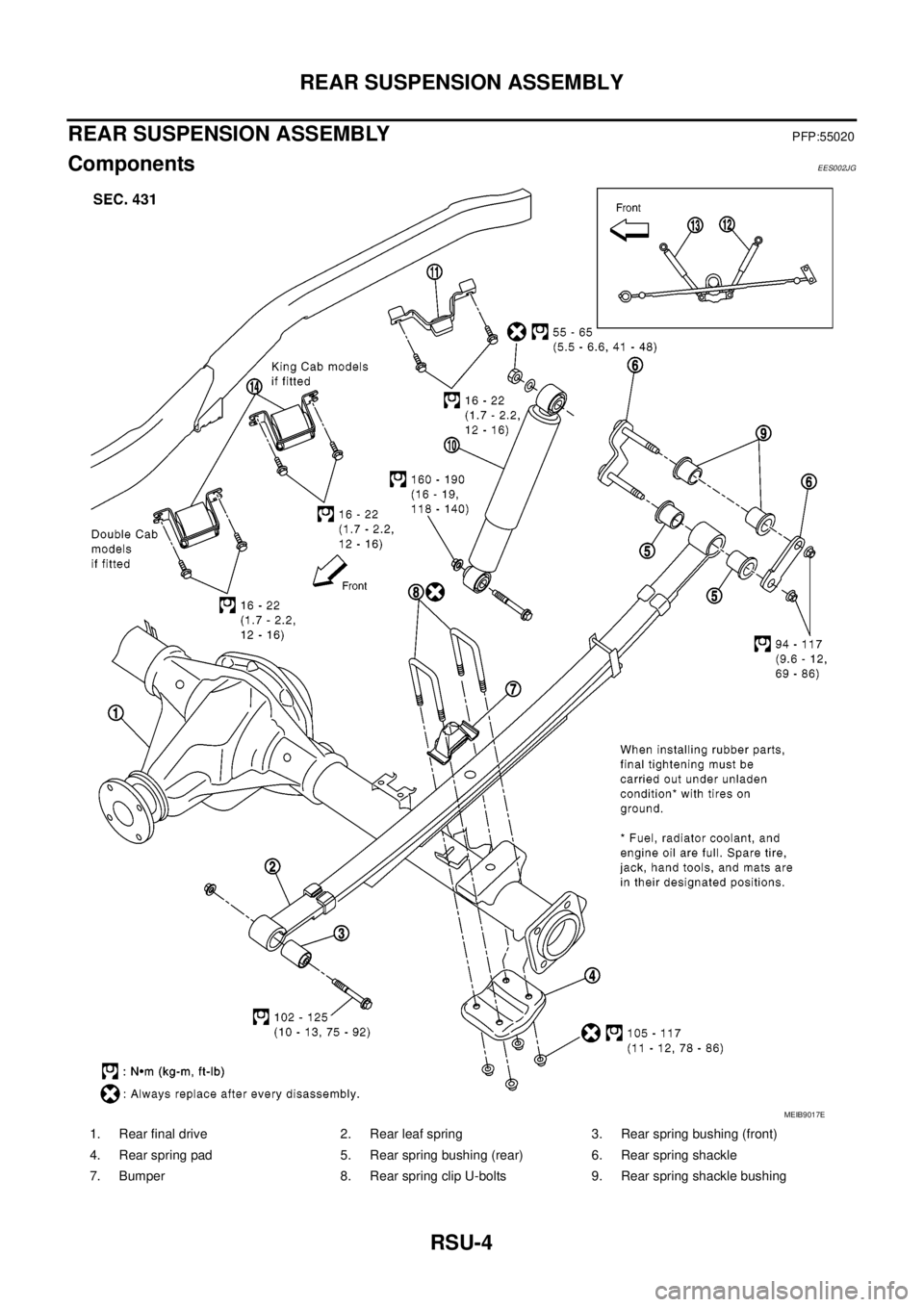
ComponentsEES002JG
1. Rear final drive 2. Rear leaf spring 3. Rear spring bushing (front)
4. Rear spring pad 5. Rear spring bushing (rear) 6. Rear spring shackle
7. Bumper 8. Rear spring clip U-bolts 9. Rear spring shackle bushing
MEIB9017E
Page 2810 of 3171

REAR SUSPENSION ASSEMBLY
RSU-5
C
D
F
G
H
I
J
K
L
MA
B
RSU
CAUTION:
When installing the components with rubber bushings, the final tightening of the nuts and bolts must
be done with the vehicle in an unladen condition (the fuel, engine coolant, and engine oil full; the
spare tire, jack, hand tools and mats in their designated positions) with the tires on the ground.
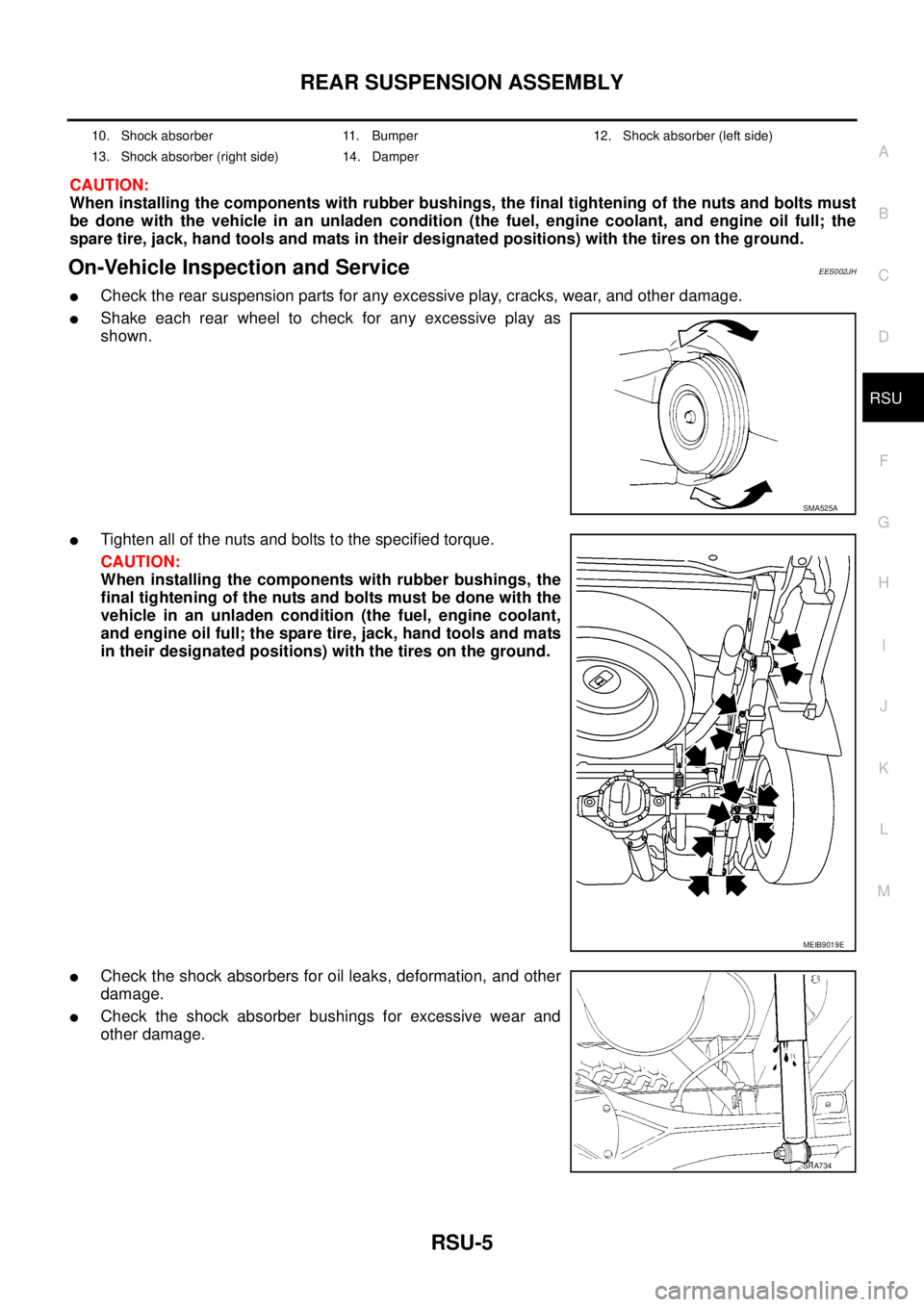
On-Vehicle Inspection and ServiceEES002JH
lCheck the rear suspension parts for any excessive play, cracks, wear, and other damage.
lShake each rear wheel to check for any excessive play as
shown.
lTighten all of the nuts and bolts to the specified torque.
CAUTION:
When installing the components with rubber bushings, the
final tightening of the nuts and bolts must be done with the
vehicle in an unladen condition (the fuel, engine coolant,
and engine oil full; the spare tire, jack, hand tools and mats
in their designated positions) with the tires on the ground.
lCheck the shock absorbers for oil leaks, deformation, and other
damage.
lCheck the shock absorber bushings for excessive wear and
other damage.
10. Shock absorber 11. Bumper 12. Shock absorber (left side)
13. Shock absorber (right side) 14. Damper
SMA525A
MEIB9019E
SRA734