NISSAN NAVARA 2005 Repair Workshop Manual
Manufacturer: NISSAN, Model Year: 2005, Model line: NAVARA, Model: NISSAN NAVARA 2005Pages: 3171, PDF Size: 49.59 MB
Page 2811 of 3171
RSU-6
SHOCK ABSORBER
SHOCK ABSORBER
PFP:56210
Removal and InstallationEES002JI
REMOVAL
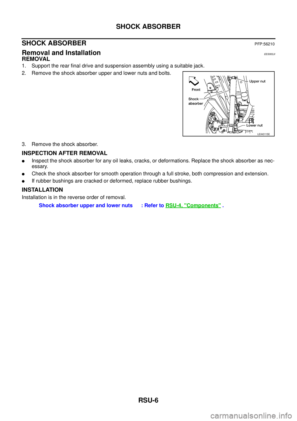
1. Support the rear final drive and suspension assembly using a suitable jack.
2. Remove the shock absorber upper and lower nuts and bolts.
3. Remove the shock absorber.
INSPECTION AFTER REMOVAL
lInspect the shock absorber for any oil leaks, cracks, or deformations. Replace the shock absorber as nec-
essary.
lCheck the shock absorber for smooth operation through a full stroke, both compression and extension.
lIf rubber bushings are cracked or deformed, replace rubber bushings.
INSTALLATION
Installation is in the reverse order of removal.
LEIA0115E
Shock absorber upper and lower nuts : Refer toRSU-4, "Components".
Page 2812 of 3171
LEAF SPRING
RSU-7
C
D
F
G
H
I
J
K
L
MA
B
RSU
LEAF SPRINGPFP:55020
Removal and InstallationEES002JJ
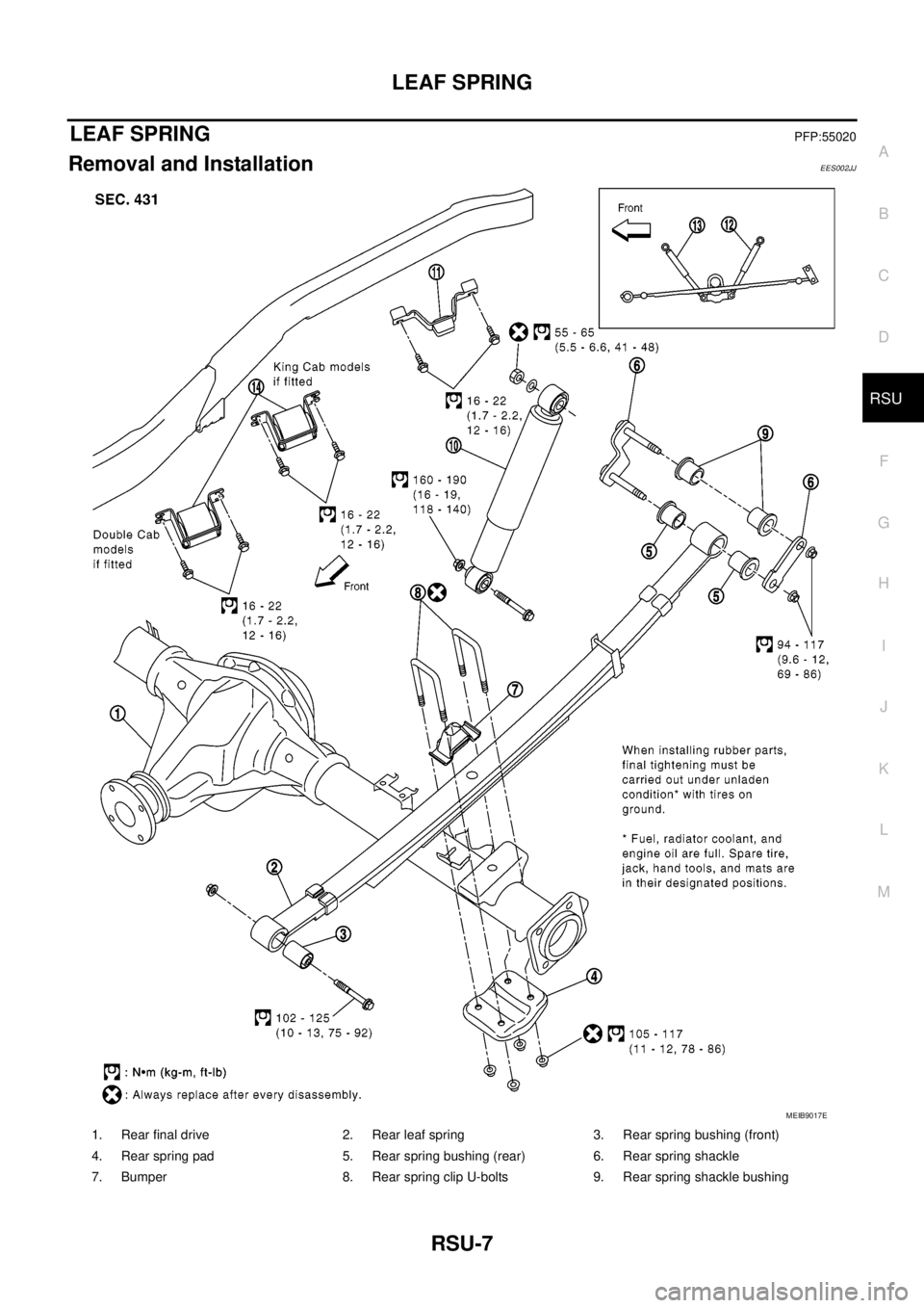
1. Rear final drive 2. Rear leaf spring 3. Rear spring bushing (front)
4. Rear spring pad 5. Rear spring bushing (rear) 6. Rear spring shackle
7. Bumper 8. Rear spring clip U-bolts 9. Rear spring shackle bushing
MEIB9017E
Page 2813 of 3171
RSU-8
LEAF SPRING
CAUTION:
When installing the components with rubber bushings, the final tightening of the nuts and bolts must
be done with the vehicle in an unladen condition (the fuel, engine coolant, and engine oil full; the
spare tire, jack, hand tools and mats in their designated positions) with the tires on the ground.
REMOVAL
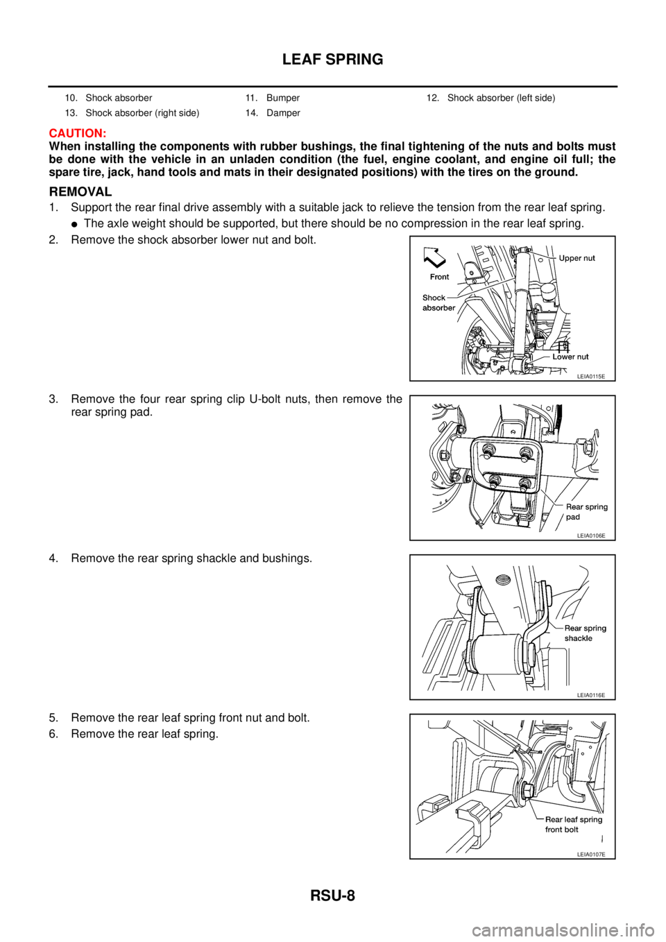
1. Support the rear final drive assembly with a suitable jack to relieve the tension from the rear leaf spring.
lThe axle weight should be supported, but there should be no compression in the rear leaf spring.
2. Remove the shock absorber lower nut and bolt.
3. Remove the four rear spring clip U-bolt nuts, then remove the
rear spring pad.
4. Remove the rear spring shackle and bushings.
5. Remove the rear leaf spring front nut and bolt.
6. Remove the rear leaf spring.
10. Shock absorber 11. Bumper 12. Shock absorber (left side)
13. Shock absorber (right side) 14. Damper
LEIA0115E
LEIA0106E
LEIA0116E
LEIA0107E
Page 2814 of 3171
LEAF SPRING
RSU-9
C
D
F
G
H
I
J
K
L
MA
B
RSU
INSPECTION AFTER REMOVAL
lCheck the rear leaf spring for any cracks or damage. Replace the rear leaf spring if necessary.
lCheck the rear spring shackle, rear spring clip U-bolts, bumper, and rear spring pad for excessive wear,
cracks, straightness, and damage. Replace any components if necessary.
lCheck all bushings for deformation and cracks. Replace any bushings if necessary.
INSTALLATION
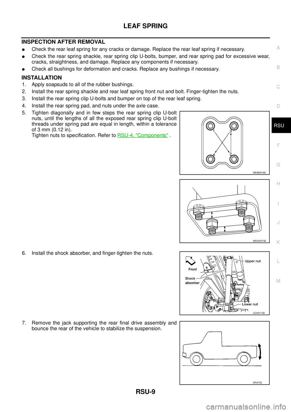
1. Apply soapsuds to all of the rubber bushings.
2. Install the rear spring shackle and rear leaf spring front nut and bolt. Finger-tighten the nuts.
3. Install the rear spring clip U-bolts and bumper on top of the rear leaf spring.
4. Install the rear spring pad, and nuts under the axle case.
5. Tighten diagonally and in few steps the rear spring clip U-bolt
nuts, until the lengths of all the exposed rear spring clip U-bolt
threads under spring pad are equal in length, within a tolerance
of 3 mm (0.12 in).
Tighten nuts to specification. Refer toRSU-4, "
Components".
6. Install the shock absorber, and finger-tighten the nuts.
7. Remove the jack supporting the rear final drive assembly and
bounce the rear of the vehicle to stabilize the suspension.
MEIB9018E
WEIA0075E
LEIA0115E
SRA703
Page 2815 of 3171
RSU-10
LEAF SPRING
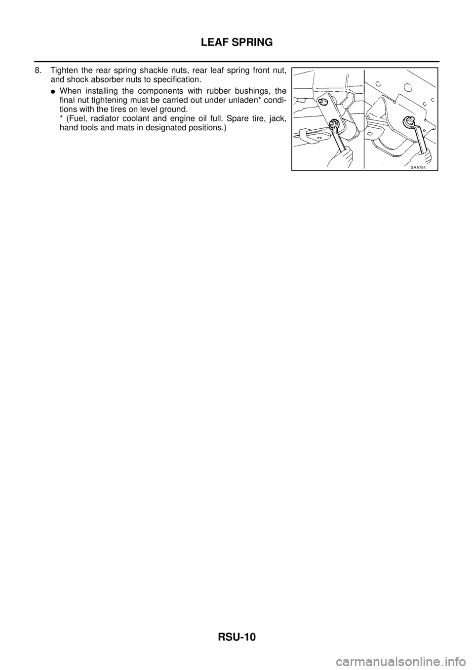
8. Tighten the rear spring shackle nuts, rear leaf spring front nut,
and shock absorber nuts to specification.
lWhen installing the components with rubber bushings, the
final nut tightening must be carried out under unladen* condi-
tions with the tires on level ground.
* (Fuel, radiator coolant and engine oil full. Spare tire, jack,
hand tools and mats in designated positions.)
SRA754
Page 2816 of 3171
SERVICE DATA AND SPECIFICATIONS (SDS)
RSU-11
C
D
F
G
H
I
J
K
L
MA
B
RSU
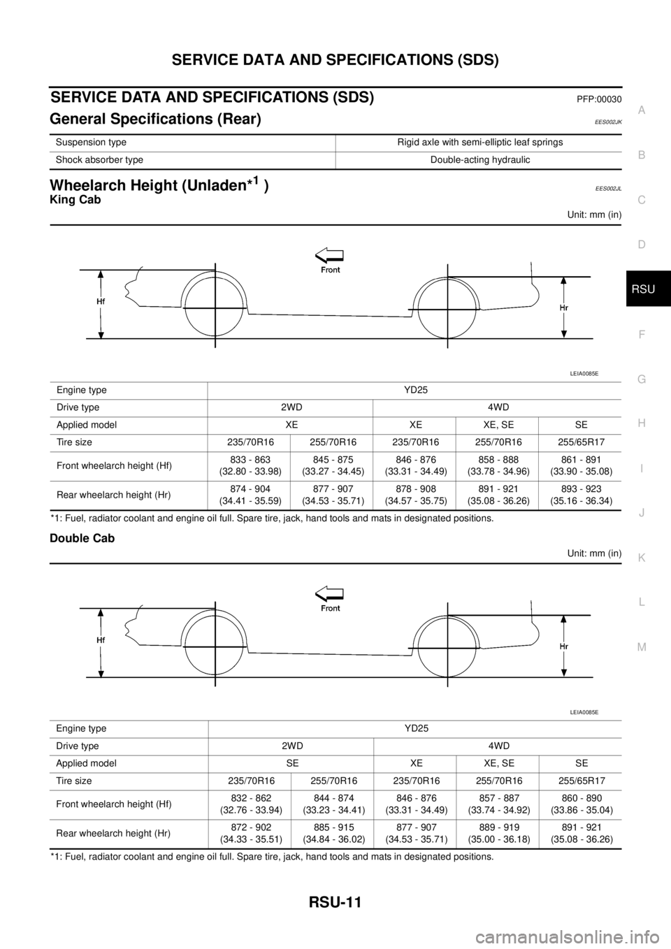
SERVICE DATA AND SPECIFICATIONS (SDS)PFP:00030
General Specifications (Rear)EES002JK
Wheelarch Height (Unladen*1)EES002JL
King Cab
Unit: mm (in)
*1: Fuel, radiator coolant and engine oil full. Spare tire, jack, hand tools and mats in designated positions.
Double Cab
Unit: mm (in)
*1: Fuel, radiator coolant and engine oil full. Spare tire, jack, hand tools and mats in designated positions.Suspension type Rigid axle with semi-elliptic leaf springs
Shock absorber type Double-acting hydraulic
Engine type YD25
Drive type 2WD 4WD
Applied model XE XE XE, SE SE
Tire size 235/70R16 255/70R16 235/70R16 255/70R16 255/65R17
Front wheelarch height (Hf)833 - 863
(32.80 - 33.98)845 - 875
(33.27 - 34.45)846 - 876
(33.31 - 34.49)858 - 888
(33.78 - 34.96)861 - 891
(33.90 - 35.08)
Rear wheelarch height (Hr)874 - 904
(34.41 - 35.59)877 - 907
(34.53 - 35.71)878 - 908
(34.57 - 35.75)891 - 921
(35.08 - 36.26)893 - 923
(35.16 - 36.34)
LEIA0085E
Engine type YD25
Drive type 2WD 4WD
Applied model SE XE XE, SE SE
Tire size 235/70R16 255/70R16 235/70R16 255/70R16 255/65R17
Front wheelarch height (Hf)832 - 862
(32.76 - 33.94)844 - 874
(33.23 - 34.41)846 - 876
(33.31 - 34.49)857 - 887
(33.74 - 34.92)860 - 890
(33.86 - 35.04)
Rear wheelarch height (Hr)872 - 902
(34.33 - 35.51)885 - 915
(34.84 - 36.02)877 - 907
(34.53 - 35.71)889 - 919
(35.00 - 36.18)891 - 921
(35.08 - 36.26)
LEIA0085E
Page 2817 of 3171

RSU-12
SERVICE DATA AND SPECIFICATIONS (SDS)
Page 2818 of 3171
SB-1
SEAT BELTS
H RESTRAINTS
CONTENTS
C
D
E
F
G
I
J
K
L
M
SECTIONSB
A
B
SB
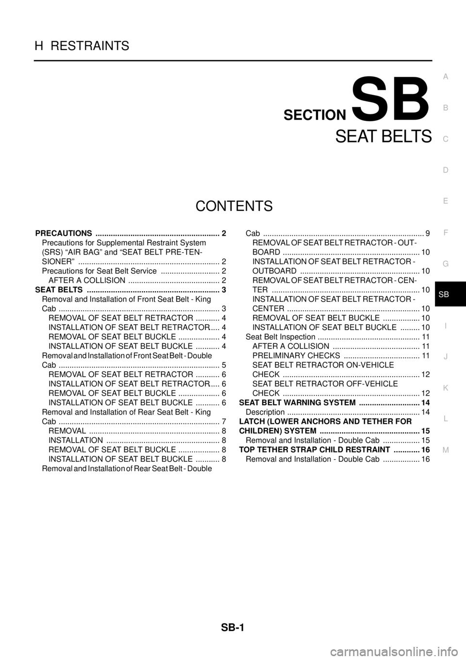
SEAT BELTS
PRECAUTIONS .......................................................... 2
Precautions for Supplemental Restraint System
(SRS)“AIRBAG”and“SEATBELTPRE-TEN-
SIONER” .................................................................. 2
Precautions for Seat Belt Service ............................ 2
AFTER A COLLISION ........................................... 2
SEAT BELTS .............................................................. 3
Removal and Installation of Front Seat Belt - King
Cab ........................................................................... 3
REMOVAL OF SEAT BELT RETRACTOR ............ 4
INSTALLATION OF SEAT BELT RETRACTOR..... 4
REMOVAL OF SEAT BELT BUCKLE .................... 4
INSTALLATION OF SEAT BELT BUCKLE ............ 4
Removal and Installation of Front Seat Belt - Double
Cab ........................................................................... 5
REMOVAL OF SEAT BELT RETRACTOR ............ 6
INSTALLATION OF SEAT BELT RETRACTOR..... 6
REMOVAL OF SEAT BELT BUCKLE .................... 6
INSTALLATION OF SEAT BELT BUCKLE ............ 6
Removal and Installation of Rear Seat Belt - King
Cab ........................................................................... 7
REMOVAL ............................................................. 8
INSTALLATION ..................................................... 8
REMOVAL OF SEAT BELT BUCKLE .................... 8
INSTALLATION OF SEAT BELT BUCKLE ............ 8
Removal and Installation of Rear Seat Belt - DoubleCab ........................................................................... 9
REMOVAL OF SEAT BELT RETRACTOR - OUT-
BOARD ................................................................ 10
INSTALLATION OF SEAT BELT RETRACTOR -
OUTBOARD ........................................................ 10
REMOVALOFSEATBELTRETRACTOR-CEN-
TER ..................................................................... 10
INSTALLATION OF SEAT BELT RETRACTOR -
CENTER .............................................................. 10
REMOVAL OF SEAT BELT BUCKLE .................. 10
INSTALLATION OF SEAT BELT BUCKLE .......... 10
Seat Belt Inspection ................................................ 11
AFTER A COLLISION ......................................... 11
PRELIMINARY CHECKS .................................... 11
SEAT BELT RETRACTOR ON-VEHICLE
CHECK ................................................................ 12
SEAT BELT RETRACTOR OFF-VEHICLE
CHECK ................................................................ 12
SEAT BELT WARNING SYSTEM ............................. 14
Description .............................................................. 14
LATCH (LOWER ANCHORS AND TETHER FOR
CHILDREN) SYSTEM ............................................... 15
Removal and Installation - Double Cab .................. 15
TOP TETHER STRAP CHILD RESTRAINT ............. 16
Removal and Installation - Double Cab .................. 16
Page 2819 of 3171
SB-2
PRECAUTIONS
PRECAUTIONS
PFP:00001
Precautions for Supplemental Restraint System (SRS) “AIR BAG” and “SEAT
BELT PRE-TENSIONER”
EHS0026D
The Supplemental Restraint System such as “AIR BAG” and “SEAT BELT PRE-TENSIONER”, used along
with a front seat belt, helps to reduce the risk or severity of injury to the driver and front passenger for certain
types of collision. Information necessary to service the system safely is included in the SRS and SB section of
this Service Manual.
WARNING:
lTo avoid rendering the SRS inoperative, which could increase the risk of personal injury or death
in the event of a collision which would result in air bag inflation, all maintenance must be per-
formed by an authorized NISSAN/INFINITI dealer.
lImproper maintenance, including incorrect removal and installation of the SRS, can lead to per-
sonal injury caused by unintentional activation of the system. For removal of Spiral Cable and Air
Bag Module, see the SRS section.
lDo not use electrical test equipment on any circuit related to the SRS unless instructed to in this
Service Manual. SRS wiring harnesses can be identified by yellow and/or orange harnesses or
harness connectors.
Precautions for Seat Belt ServiceEHS00265
CAUTION:
lBefore removing the seat belt pre-tensioner assembly, turn the ignition switch OFF, disconnect
both battery cables and wait at least 3 minutes.
lDo not use electrical test equipment for seat belt pre-tensioner connector.
lAfter replacing or reinstalling seat belt pre-tensioner assembly, or reconnecting seat belt pre-
tensioner assembly connector, ensure entire SRS operates properly. Refer toSRS-18, "
SRS Oper-
ation Check".
lDeploy seat belt pre-tensioner assembly before disposing. Refer toSRS-49, "DISPOSAL OF AIR
BAG MODULE AND SEAT BELT PRE-TENSIONER".
lDo not disassemble buckle or seat belt assembly.
lReplace anchor bolts if they are deformed or worn out.
lNever oil tongue and buckle.
lIf any component of seat belt assembly is questionable, do not repair. Replace the whole seat belt
assembly.
lIf webbing is cut, frayed, or damaged, replace seat belt assembly.
lWhen replacing seat belt assembly, use a genuine NISSAN seat belt assembly.
AFTER A COLLISION
WARNING:
lInspect all seat belt assemblies including retractors and attaching hardware after any collision.
lNISSAN recommends that all seat belt assemblies in use during a collision be replaced unless the
collision was minor and the belts show no damage and continue to operate properly. Failure to do
so could result in serious personal injury in an accident. Seat belt assemblies not in use during a
collision should also be replaced if either damage or improper operation is noted. Seat belt pre-
tensioner should be replaced even if the seat belts are not in use during a frontal collision in which
the air bags are deployed.
Replace any seat belt assembly (including anchor bolts) if:
lThe seat belt was in use at the time of a collision (except for minor collisions and the belts, retractors and
buckles show no damage and continue to operate properly).
lThe seat belt was damaged in an accident. (i.e., torn webbing, bent retractor or guide, etc.)
lThe seat belt attaching point was damaged in an accident. Inspect the seat belt attaching area for damage
or distortion and repair as necessary before installing a new seat belt assembly.
lAnchor bolts are deformed or worn out.
lThe seat belt pre-tensioner should be replaced even if the seat belts are not in use during the collision in
which the air bags are deployed.
Page 2820 of 3171
SEAT BELTS
SB-3
C
D
E
F
G
I
J
K
L
MA
B
SB
SEAT BELTSPFP:86884
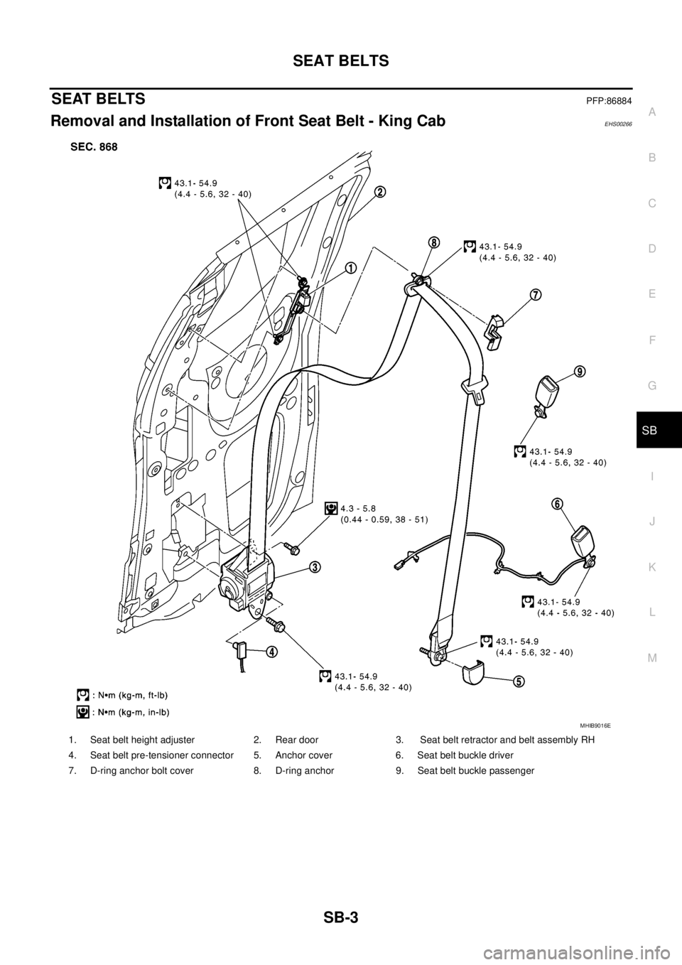
Removal and Installation of Front Seat Belt - King CabEHS00266
1. Seat belt height adjuster 2. Rear door 3. Seat belt retractor and belt assembly RH
4. Seat belt pre-tensioner connector 5. Anchor cover 6. Seat belt buckle driver
7. D-ring anchor bolt cover 8. D-ring anchor 9. Seat belt buckle passenger
MHIB9016E