suspension NISSAN NAVARA 2005 Repair Owner's Manual
[x] Cancel search | Manufacturer: NISSAN, Model Year: 2005, Model line: NAVARA, Model: NISSAN NAVARA 2005Pages: 3171, PDF Size: 49.59 MB
Page 2313 of 3171
MA-38
CHASSIS AND BODY MAINTENANCE
Checking Axle and Suspension Parts
ELS001J5
FRONT AND REAR AXLE AND SUSPENSION PARTS
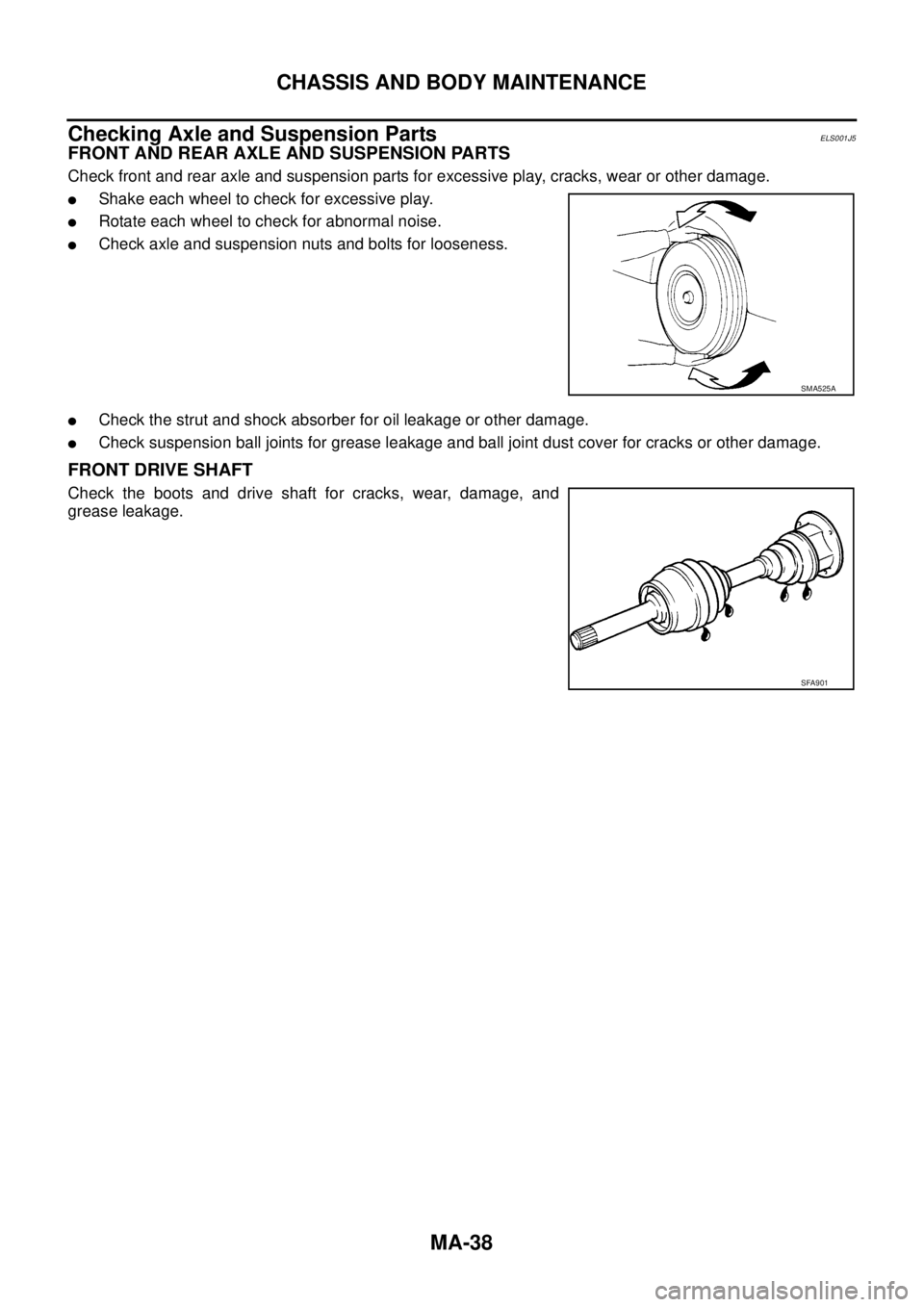
Check front and rear axle and suspension parts for excessive play, cracks, wear or other damage.
lShake each wheel to check for excessive play.
lRotate each wheel to check for abnormal noise.
lCheck axle and suspension nuts and bolts for looseness.
lCheck the strut and shock absorber for oil leakage or other damage.
lCheck suspension ball joints for grease leakage and ball joint dust cover for cracks or other damage.
FRONT DRIVE SHAFT
Check the boots and drive shaft for cracks, wear, damage, and
grease leakage.
SMA525A
SFA901
Page 2544 of 3171
IPDM E/R (INTELLIGENT POWER DISTRIBUTION MODULE ENGINE ROOM)
PG-15
C
D
E
F
G
H
I
J
L
MA
B
PG
IPDM E/R STATUS CONTROL
In order to save power, IPDM E/R switches status by itself based on each operating condition.
1. CAN communication status
lCAN communication is normally performed with other control units.
lIndividual unit control by IPDM E/R is normally performed.
lA status is changed into sleep transient status when receiving a sleep request signal from BCM while
all the systems controlled by IPDM E/R under suspension.
2. Sleep transient status
lProcess to stop CAN communication is activated.
lAll systems controlled by IPDM E/R are stopped. When 3 second has elapsed after CAN communica-
tion with other control units is stopped, status switches to sleep status.
3. Sleep status
lIPDM E/R operates in low power mode.
lCAN communication is stopped.
lWhen a change in CAN communication signal is detected, status switches to CAN communication sta-
tus.
lWhen a change in ignition switch signal is detected, status switches to CAN communication status.
CAN Communication System DescriptionEKS00PA9
Refer toLAN-23, "CAN COMMUNICATION".
Function of Detecting Ignition Relay MalfunctionEKS00PAA
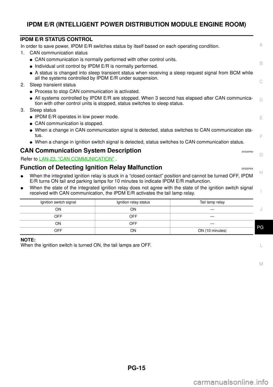
lWhen the integrated ignition relay is stuck in a “closed contact” position and cannot be turned OFF, IPDM
E/R turns ON tail and parking lamps for 10 minutes to indicate IPDM E/R malfunction.
lWhen the state of the integrated ignition relay does not agree with the state of the ignition switch signal
received with CAN communication, the IPDM E/R activates the tail lamp relay.
NOTE:
When the ignition switch is turned ON, the tail lamps are OFF.
Ignition switch signal Ignition relay status Tail lamp relay
ON ON —
OFF OFF —
ON OFF —
OFF ON ON (10 minutes)
Page 2617 of 3171
PR-2
NOISE, VIBRATION, AND HARSHNESS (NVH) TROUBLESHOOTING
NOISE, VIBRATION, AND HARSHNESS (NVH) TROUBLESHOOTING
PFP:00003
NVH Troubleshooting ChartEDS002WN
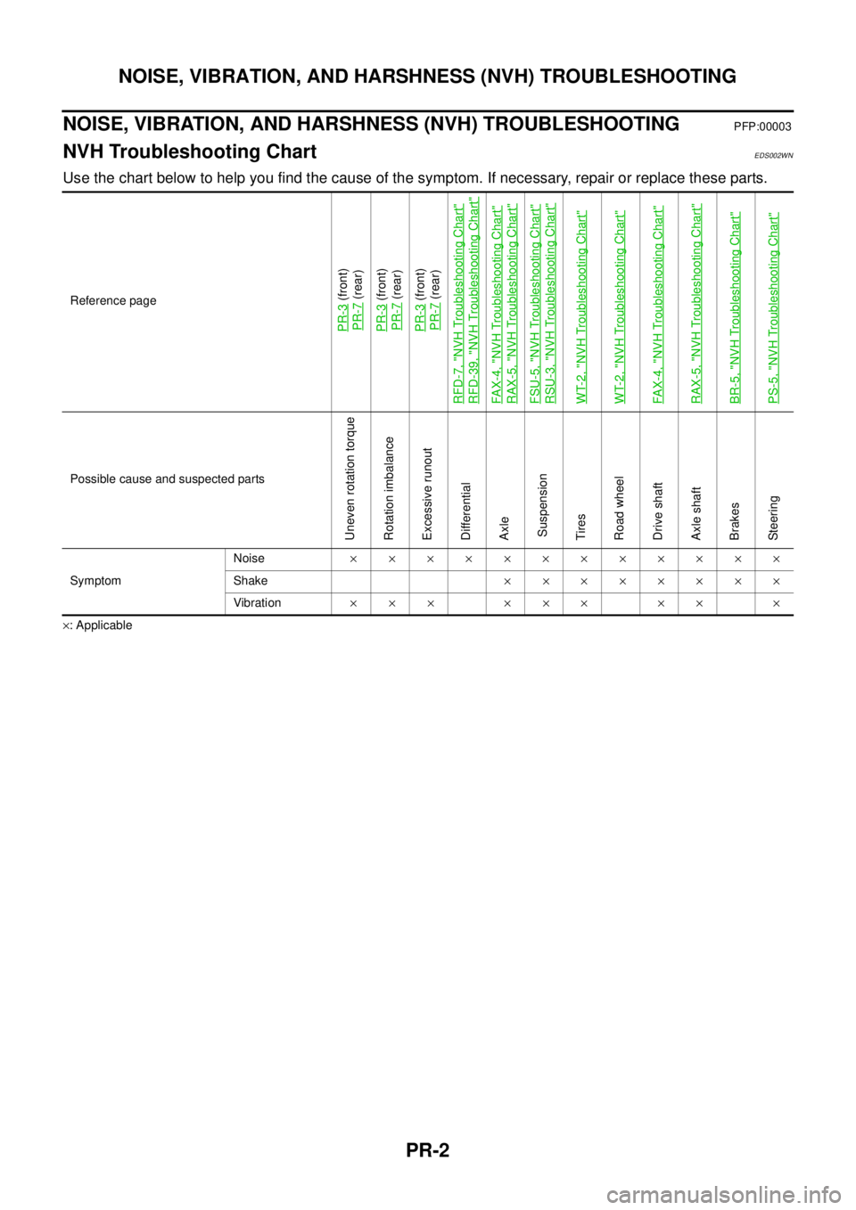
Use the chart below to help you find the cause of the symptom. If necessary, repair or replace these parts.
´: ApplicableReference page
PR-3
(front)
PR-7(rear)
PR-3(front)
PR-7(rear)
PR-3(front)
PR-7(rear)
RFD-7, "
NVH Troubleshooting Chart
"
RFD-39, "
NVH Troubleshooting Chart
"
FA X -4 , "
NVH Troubleshooting Chart
"
RAX-5, "
NVH Troubleshooting Chart
"
FSU-5, "
NVH Troubleshooting Chart
"
RSU-3, "
NVH Troubleshooting Chart
"
WT-2, "
NVH Troubleshooting Chart
"
WT-2, "
NVH Troubleshooting Chart
"
FA X -4 , "
NVH Troubleshooting Chart
"
RAX-5, "
NVH Troubleshooting Chart
"
BR-5, "
NVH Troubleshooting Chart
"
PS-5, "
NVH Troubleshooting Chart
"
Possible cause and suspected parts
Uneven rotation torque
Rotation imbalance
Excessive runout
Differential
Axle
Suspension
Tires
Road wheel
Drive shaft
Axle shaft
Brakes
Steering
SymptomNoise´´´´´´´´´´´´
Shake´´´´´´´´
Vibration´´´ ´´´ ´´ ´
Page 2632 of 3171

NOISE, VIBRATION, AND HARSHNESS (NVH) TROUBLESHOOTING
PS-5
C
D
E
F
H
I
J
K
L
MA
B
PS
NOISE, VIBRATION, AND HARSHNESS (NVH) TROUBLESHOOTINGPFP:00003
NVH Troubleshooting ChartEGS001LC
Use chart below to help you find the cause of the symptom. If necessary, repair or replace these parts.
´: ApplicableReference page
PS-6PS-6PS-18PS-18PS-18PS-6PS-8PS-8EM-12PS-8—
PS-18PS-12PS-11PS-16
NVHinPRsection
NVH in RFD section
NVH in FAX, RAX, FSU, RSU section
NVH in WT section
NVH in WT section
NVHinBRsection
NVHinBRsection
Possible cause and SUSPECTED PARTS
Fluid level
Air in hydraulic system
Outer socket ball joint swinging force
Outer socket ball joint rotating torque
Outer socket ball joint end play
Steering fluid leakage
Steering wheel play
Steering gear rack sliding force
Drive belt looseness
Improper steering wheel
Improper installation or looseness of tilt lock lever
Mounting rubber deterioration
Steering column deformation or damage
Improper installation or looseness of steering column
Steering linkage looseness
PROPELLER SHAFT
DIFFERENTIAL
AXLE and SUSPENSION
TYRES
ROAD WHEEL
DRIVE SHAFT
BRAKES
Symptom SteeringNoise´ ´ ´´´´´ ´ ´ ´´´´´´ ´
Shake´´´ ´ ´´´´ ´
Vibration´´´´´ ´ ´´ ´
Shimmy´´´ ´ ´´´ ´
Shudder´ ´ ´´´ ´
Page 2635 of 3171
PS-8
STEERING WHEEL
STEERING WHEEL
PFP:48430
On-Vehicle Inspection and ServiceEGS001LG
CHECKING CONDITION OF INSTALLATION
lCheck installation conditions of steering gear assembly, front suspension assembly, axle and steering col-
umn assembly.
lCheck if movement exists when steering wheel is moved up and down, to the left and right and to the axial
direction.
lCheck steering gear assembly mounting bolts and nuts for looseness. Refer toPS-14, "COMPONENT".
CHECKING STEERING WHEEL PLAY
lTurn steering wheel so that front wheels come to the straight-ahead position. Start engine and lightly turn
steering wheel to the left and right until front wheels start to move. Measure steering wheel movement on
the outer circumference.
lWhen the measurement value is outside the standard value, check backlash for each joint of steering col-
umn assembly and installation condition of steering gear assembly.
CHECKING NEUTRAL POSITION STEERING WHEEL
lMake sure that steering gear assembly, steering column assembly and steering wheel are installed in the
correct position.
lPerform neutral position inspection after wheel alignment. Refer toFSU-7, "Front Wheel Alignment".
lSet vehicle to the straight-ahead position and confirm steering wheel is in the neutral position.
lLoosen outer socket lock nut and turn inner socket to left and right equally to make fine adjustment if
steering wheel is not in the neutral position.
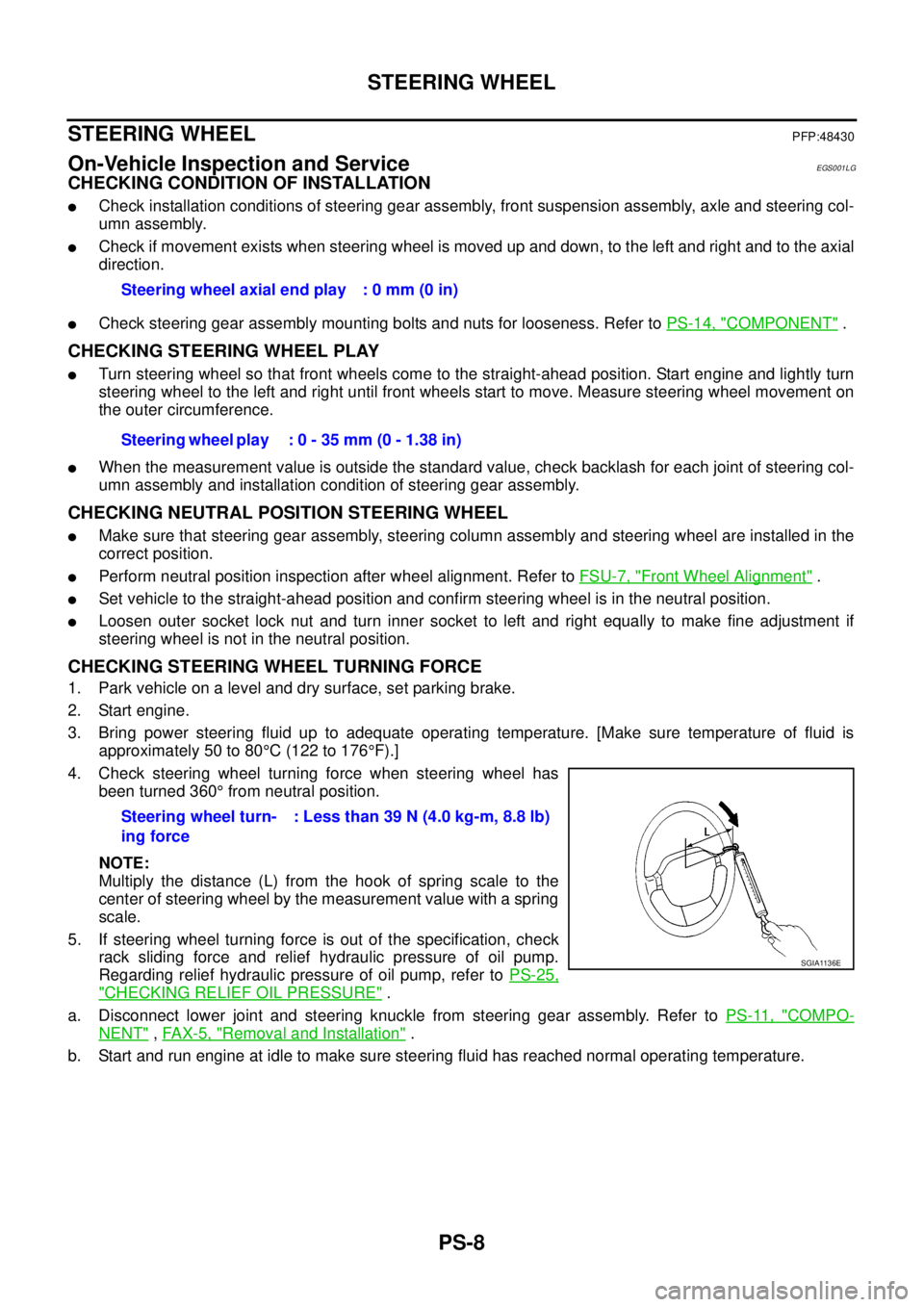
CHECKING STEERING WHEEL TURNING FORCE
1. Park vehicle on a level and dry surface, set parking brake.
2. Start engine.
3. Bring power steering fluid up to adequate operating temperature. [Make sure temperature of fluid is
approximately 50 to 80°C(122to176°F).]
4. Check steering wheel turning force when steering wheel has
been turned 360°from neutral position.
NOTE:
Multiply the distance (L) from the hook of spring scale to the
center of steering wheel by the measurement value with a spring
scale.
5. If steering wheel turning force is out of the specification, check
rack sliding force and relief hydraulic pressure of oil pump.
Regarding relief hydraulic pressure of oil pump, refer toPS-25,
"CHECKING RELIEF OIL PRESSURE".
a. Disconnect lower joint and steering knuckle from steering gear assembly. Refer toPS-11, "
COMPO-
NENT",FAX-5, "Removal and Installation".
b. Start and run engine at idle to make sure steering fluid has reached normal operating temperature.Steering wheel axial end play : 0 mm (0 in)
Steering wheel play : 0 - 35 mm (0 - 1.38 in)
Steering wheel turn-
ing force: Less than 39 N (4.0 kg-m, 8.8 lb)
SGIA1136E
Page 2636 of 3171
STEERING WHEEL
PS-9
C
D
E
F
H
I
J
K
L
MA
B
PS
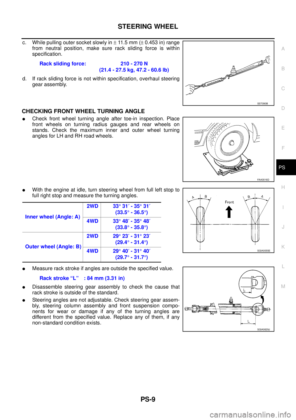
c. While pulling outer socket slowly in±11 . 5 m m (±0.453 in) range
from neutral position, make sure rack sliding force is within
specification.
d. If rack sliding force is not within specification, overhaul steering
gear assembly.
CHECKING FRONT WHEEL TURNING ANGLE
lCheck front wheel turning angle after toe-in inspection. Place
front wheels on turning radius gauges and rear wheels on
stands. Check the maximum inner and outer wheel turning
angles for LH and RH road wheels.
lWith the engine at idle, turn steering wheel from full left stop to
full right stop and measure the turning angles.
lMeasure rack stroke if angles are outside the specified value.
lDisassemble steering gear assembly to check the cause that
rack stroke is outside of the standard.
lSteering angles are not adjustable. Check steering gear assem-
bly, steering column assembly and front suspension compo-
nents for wear or damage if any of the turning angles are
different from the specified value. Replace any of them, if any
non-standard condition exists.Rack sliding force: 210 - 270 N
(21.4 - 27.5 kg, 47.2 - 60.6 lb)
SST090B
FAA0016D
Inner wheel (Angle: A)2WD 33°31¢-35°31¢
(33.5°-36.5°)
4WD 33°48¢-35°48¢
(33.8°-35.8°)
Outer wheel (Angle: B)2WD 29°23¢-31°23¢
(29.4°-31.4°)
4WD 29°40¢-31°40¢
(29.7°-31.7°)
SGIA0055E
Rack stroke “L” : 84 mm (3.31 in)
SGIA0629J
Page 2642 of 3171
POWER STEERING GEAR AND LINKAGE
PS-15
C
D
E
F
H
I
J
K
L
MA
B
PS
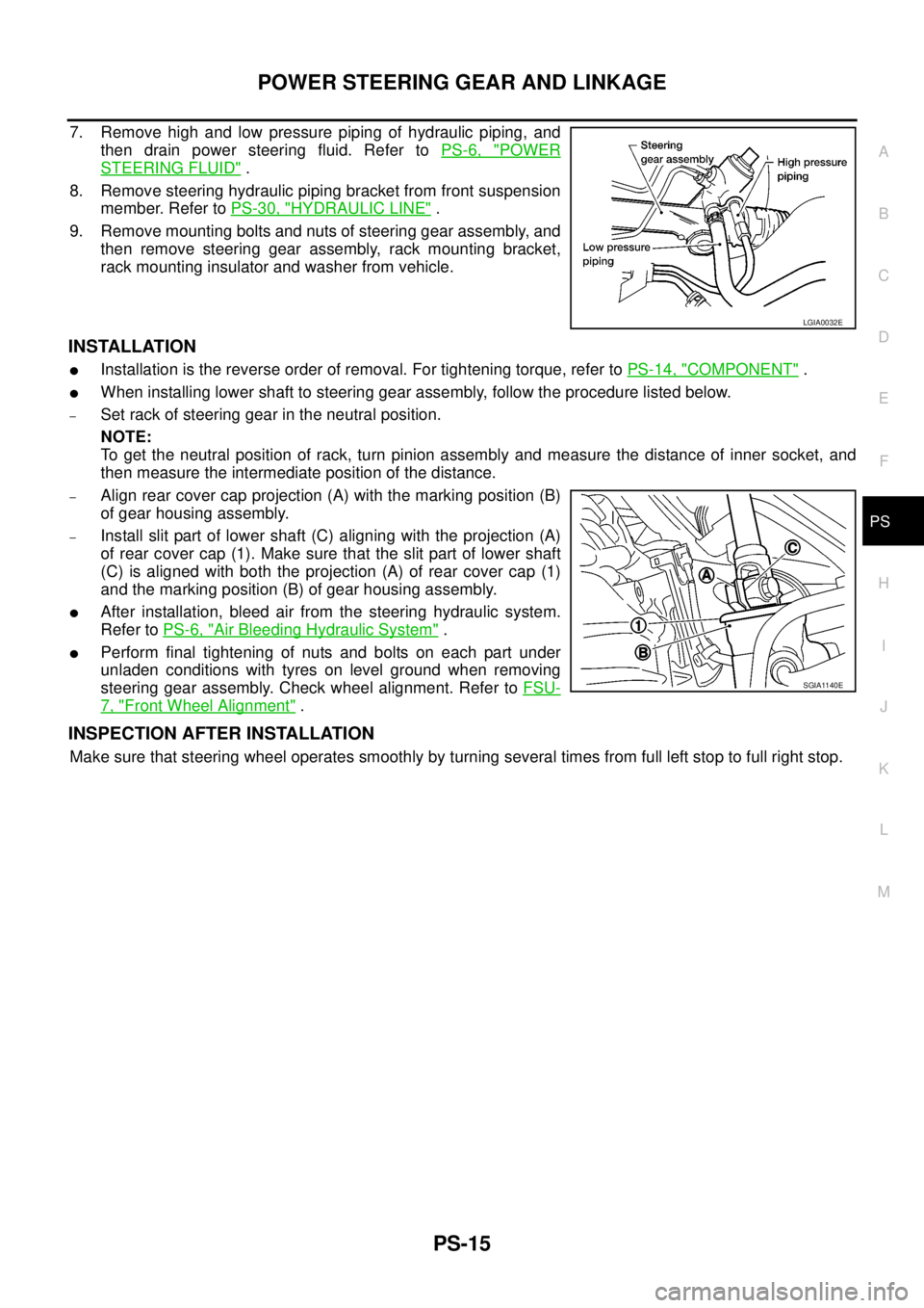
7. Remove high and low pressure piping of hydraulic piping, and
then drain power steering fluid. Refer toPS-6, "
POWER
STEERING FLUID".
8. Remove steering hydraulic piping bracket from front suspension
member. Refer toPS-30, "
HYDRAULIC LINE".
9. Remove mounting bolts and nuts of steering gear assembly, and
then remove steering gear assembly, rack mounting bracket,
rack mounting insulator and washer from vehicle.
INSTALLATION
lInstallation is the reverse order of removal. For tightening torque, refer toPS-14, "COMPONENT".
lWhen installing lower shaft to steering gear assembly, follow the procedure listed below.
–Set rack of steering gear in the neutral position.
NOTE:
To get the neutral position of rack, turn pinion assembly and measure the distance of inner socket, and
then measure the intermediate position of the distance.
–Align rear cover cap projection (A) with the marking position (B)
of gear housing assembly.
–Install slit part of lower shaft (C) aligning with the projection (A)
of rear cover cap (1). Make sure that the slit part of lower shaft
(C) is aligned with both the projection (A) of rear cover cap (1)
and the marking position (B) of gear housing assembly.
lAfter installation, bleed air from the steering hydraulic system.
Refer toPS-6, "
Air Bleeding Hydraulic System".
lPerform final tightening of nuts and bolts on each part under
unladen conditions with tyres on level ground when removing
steering gear assembly. Check wheel alignment. Refer toFSU-
7, "Front Wheel Alignment".
INSPECTION AFTER INSTALLATION
Make sure that steering wheel operates smoothly by turning several times from full left stop to full right stop.
LGIA0032E
SGIA1140E
Page 2668 of 3171
![NISSAN NAVARA 2005 Repair Owners Manual NOISE, VIBRATION, AND HARSHNESS (NVH) TROUBLESHOOTING
RAX-5
[M226]
C
E
F
G
H
I
J
K
L
MA
B
RAX
NOISE, VIBRATION, AND HARSHNESS (NVH) TROUBLESHOOTINGPFP:00003
NVH Troubleshooting ChartEDS003HW
Use the c NISSAN NAVARA 2005 Repair Owners Manual NOISE, VIBRATION, AND HARSHNESS (NVH) TROUBLESHOOTING
RAX-5
[M226]
C
E
F
G
H
I
J
K
L
MA
B
RAX
NOISE, VIBRATION, AND HARSHNESS (NVH) TROUBLESHOOTINGPFP:00003
NVH Troubleshooting ChartEDS003HW
Use the c](/img/5/57362/w960_57362-2667.png)
NOISE, VIBRATION, AND HARSHNESS (NVH) TROUBLESHOOTING
RAX-5
[M226]
C
E
F
G
H
I
J
K
L
MA
B
RAX
NOISE, VIBRATION, AND HARSHNESS (NVH) TROUBLESHOOTINGPFP:00003
NVH Troubleshooting ChartEDS003HW
Use the chart below to help you find the cause of the symptom. If necessary, repair or replace these parts.
´: Applicable Reference page
RAX-7
(M226 all)
RAX-7(M226 all)
RAX-7(M226 all)
PR-2, "
NVH Troubleshooting Chart
"
RFD-7
(with LSD),RFD-39
(with LD)
RSU-3, "
NVH Troubleshooting Chart
"
WT-2, "
NVH Troubleshooting Chart
"
WT-2, "
NVH Troubleshooting Chart
"
BR-5, "
NVH Troubleshooting Chart
"
Possible cause and SUSPECTED PARTS
Improper installation, looseness
Parts interference
Wheel bearing damage
PROPELLER SHAFT
REAR FINAL DRIVE
SUSPENSION
TIRES
ROAD WHEEL
BRAKES
SymptomNoise´´ ´´´´´´
Shake´´ ´ ´´´´
Vibration´´ ´ ´´
Shimmy´´ ´´´´
Shudder´ ´´´´
Poor quality ride or handling´´´ ´´´
Page 2710 of 3171
![NISSAN NAVARA 2005 Repair Owners Manual NOISE, VIBRATION, AND HARSHNESS (NVH) TROUBLESHOOTING
RFD-7
[WITH LIMITED SLIP DIFFERENTIAL]
C
E
F
G
H
I
J
K
L
MA
B
RFD
NOISE, VIBRATION, AND HARSHNESS (NVH) TROUBLESHOOTINGPFP:00003
NVH Troubleshooti NISSAN NAVARA 2005 Repair Owners Manual NOISE, VIBRATION, AND HARSHNESS (NVH) TROUBLESHOOTING
RFD-7
[WITH LIMITED SLIP DIFFERENTIAL]
C
E
F
G
H
I
J
K
L
MA
B
RFD
NOISE, VIBRATION, AND HARSHNESS (NVH) TROUBLESHOOTINGPFP:00003
NVH Troubleshooti](/img/5/57362/w960_57362-2709.png)
NOISE, VIBRATION, AND HARSHNESS (NVH) TROUBLESHOOTING
RFD-7
[WITH LIMITED SLIP DIFFERENTIAL]
C
E
F
G
H
I
J
K
L
MA
B
RFD
NOISE, VIBRATION, AND HARSHNESS (NVH) TROUBLESHOOTINGPFP:00003
NVH Troubleshooting ChartEDS00392
Use the chart below to help you find the cause of the symptom. If necessary, repair or replace these parts.
´: ApplicableReference page
RFD-22, "
INSPECTION AFTER DISASSEMBLY
"
RFD-16, "
Tooth Contact
"
RFD-22, "
INSPECTION AFTER DISASSEMBLY
"
RFD-17, "
Backlash
"
RFD-18, "
Companion Flange Runout
"
RFD-9, "
Checking Differential Gear Oil
"
PR-2, "
NVH Troubleshooting Chart
"
RAX-5, "
NVH Troubleshooting Chart
",RSU-3, "
NVH Troubleshooting Chart
"
WT-2, "
NVH Troubleshooting Chart
"
RAX-5, "
NVH Troubleshooting Chart
"
BR-5, "
NVH Troubleshooting Chart
"
PS-5, "
NVH Troubleshooting Chart
"
Possible cause and SUSPECTED PARTS
Gear tooth rough
Gear contact improper
Tooth surfaces worn
Backlash incorrect
Companion flange excessive runout
Gear oil improper
PROPELLER SHAFT
AXLE AND SUSPENSION
TIRES
ROAD WHEEL
AXLE SHAFT
BRAKES
STEERING
Symptom Noise´´´´´´´´´´´´´
Page 2742 of 3171
![NISSAN NAVARA 2005 Repair Owners Manual NOISE, VIBRATION AND HARSHNESS (NVH) TROUBLESHOOTING
RFD-39
[WITH ELECTRONIC LOCKING DIFFERENTIAL]
C
E
F
G
H
I
J
K
L
MA
B
RFD
NOISE, VIBRATION AND HARSHNESS (NVH) TROUBLESHOOTINGPFP:00003
NVH Troubles NISSAN NAVARA 2005 Repair Owners Manual NOISE, VIBRATION AND HARSHNESS (NVH) TROUBLESHOOTING
RFD-39
[WITH ELECTRONIC LOCKING DIFFERENTIAL]
C
E
F
G
H
I
J
K
L
MA
B
RFD
NOISE, VIBRATION AND HARSHNESS (NVH) TROUBLESHOOTINGPFP:00003
NVH Troubles](/img/5/57362/w960_57362-2741.png)
NOISE, VIBRATION AND HARSHNESS (NVH) TROUBLESHOOTING
RFD-39
[WITH ELECTRONIC LOCKING DIFFERENTIAL]
C
E
F
G
H
I
J
K
L
MA
B
RFD
NOISE, VIBRATION AND HARSHNESS (NVH) TROUBLESHOOTINGPFP:00003
NVH Troubleshooting ChartEDS003AM
Use the chart below to help you find the cause of the symptom. If necessary, repair or replace these parts.
´: ApplicableReference page
RFD-90, "
INSPECTION AFTER DISASSEMBLY
"
RFD-83, "
Tooth Contact
"
RFD-90, "
INSPECTION AFTER DISASSEMBLY
"
RFD-84, "
Backlash
"
RFD-85, "
Companion Flange Runout
"
RFD-40, "
Checking Differential Gear Oil
"
PR-2, "
NVH Troubleshooting Chart
"
RAX-5, "
NVH Troubleshooting Chart
",RSU-3, "
NVH Troubleshooting Chart
"
WT-2, "
NVH Troubleshooting Chart
"
RAX-5, "
NVH Troubleshooting Chart
"
BR-5, "
NVH Troubleshooting Chart
"
PS-5, "
NVH Troubleshooting Chart
"
Possible cause and SUSPECTED PARTS
Gear tooth rough
Gear contact improper
Tooth surfaces worn
Backlash incorrect
Companion flange excessive runout
Gear oil improper
PROPELLER SHAFT
AXLE AND SUSPENSION
TIRES
ROAD WHEEL
AXLE SHAFT
BRAKES
STEERING
Symptom Noise´´´´´´´´´´´´´