Cylinder block NISSAN NAVARA 2005 Repair Workshop Manual
[x] Cancel search | Manufacturer: NISSAN, Model Year: 2005, Model line: NAVARA, Model: NISSAN NAVARA 2005Pages: 3171, PDF Size: 49.59 MB
Page 476 of 3171
ATC-142
REFRIGERANT LINES
Removal and Installation for Compressor
EJS006CN
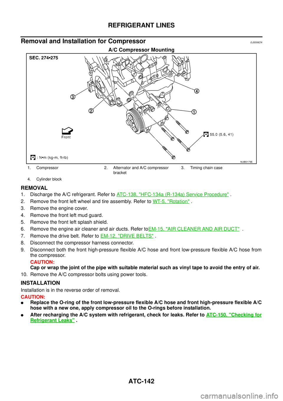
A/C Compressor Mounting
REMOVAL
1. Discharge the A/C refrigerant. Refer toATC-138, "HFC-134a (R-134a) Service Procedure".
2. Remove the front left wheel and tire assembly. Refer toWT-5, "
Rotation".
3. Remove the engine cover.
4. Remove the front left mud guard.
5. Remove the front left splash shield.
6. Remove the engine air cleaner and air ducts. Refer toEM-15, "
AIR CLEANER AND AIR DUCT".
7. Remove the drive belt. Refer toEM-12, "
DRIVE BELTS".
8. Disconnect the compressor harness connector.
9. Disconnect both the front high-pressure flexible A/C hose and front low-pressure flexible A/C hose from
the compressor.
CAUTION:
Cap or wrap the joint of the pipe with suitable material such as vinyl tape to avoid the entry of air.
10. Remove the A/C compressor bolts using power tools.
INSTALLATION
Installation is in the reverse order of removal.
CAUTION:
lReplace the O-ring of the front low-pressure flexible A/C hose and front high-pressure flexible A/C
hose with a new one, apply compressor oil to the O-rings before installation.
lAfter recharging the A/C system with refrigerant, check for leaks. Refer toATC-150, "Checking for
Refrigerant Leaks".
MJIB0179E
1. Compressor 2. Alternator and A/C compressor
bracket3. Timing chain case
4. Cylinder block
Page 607 of 3171

POWERDOORLOCKSYSTEM
BL-23
C
D
E
F
G
H
J
K
L
MA
B
BL
System DescriptionEIS00D7R
Power is supplied at all times
lthrough 50A fusible link (letterG, located in the fuse and fusible link box)
lto BCM terminal 57
lthrough 10A fuse [No. 21, located in the fuse block (J/B)]
lto BCM terminal 41
lthrough 10A fuse [No. 22, located in the fuse block (J/B)]
lto key switch terminal 2.
When key switch is ON, power is supplied
lthrough key switch terminal 1
lto BCM terminal 5.
When ignition switch is in ON or START position
lthrough 10A fuse [No. 1, located in the fuse block (J/B)]
lto BCM terminal 3.
Ground is supplied
lto BCM terminal 55
lthrough body grounds M21, M80 and M83.
Door switch operation
When front door switch (driver side) is ON (door is OPEN), ground is supplied
lto BCM terminal 15
lthrough front door switch (driver side) terminal 2
lthrough front door switch (driver side) case ground.
When front door switch (passenger side) is ON (door is OPEN), ground is supplied
lto BCM terminal 14
lthrough front door switch (passenger side) terminal 2
lthrough front door switch (passenger side) case ground.
When rear door switch LH is ON (door is OPEN), ground is supplied (Double cab model)
lto BCM terminal 16
lthrough rear door switch LH terminal 2
lthrough rear door switch LH case ground.
When rear door switch RH is ON (door is OPEN), ground is supplied (Double cab model)
lto BCM terminal 12
lthrough rear door switch RH terminal 2
lthrough rear door switch RH case ground.
Key cylinder switch operation (Without multi-remote control system)
When key cylinder is turned to lock position, ground is supplied
lthrough BCM terminal 34
lto key cylinder switch (driver and passenger side) terminals 4
lthrough key cylinder switch (driver and passenger side) terminals 5
lthrough body ground M21, M80 and M83
then all doors are locked.
When key cylinder is turned to unlock position, ground is supplied
lthrough BCM terminal 32
lto key cylinder switch (driver and passenger side) terminal 6
lthrough key cylinder switch (driver and passenger side) terminal 5
lthrough body ground M21, M80 and M83
then all doors are unlocked.
Power door lock operation with door lock/unlock switch
When doors are lock by door lock/unlock switch, ground is supplied
Page 621 of 3171
POWERDOORLOCKSYSTEM
BL-37
C
D
E
F
G
H
J
K
L
MA
B
BL
Work FlowEIS00D81
1. Check the symptom and customer's requests.
2. Understand the outline of system. Refer toBL-23, "
System Description".
3. According to the trouble diagnosis, repair or replace the cause of the malfunction. Refer toBL-37, "
Trou-
ble Diagnoses Chart by Symptom".
4. Does power door lock system operate normally?
YES: GO TO 5.
NO:GOTO2.
5. INSPECTION END.
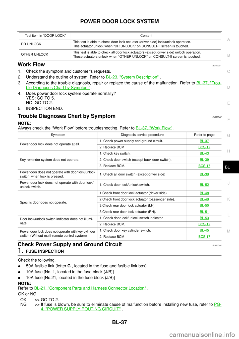
Trouble Diagnoses Chart by SymptomEIS00D82
NOTE:
Always check the “Work Flow” before troubleshooting. Refer toBL-37, "
Work Flow".
Check Power Supply and Ground CircuitEIS00D84
1.FUSE INSPECTION
Check the following.
l50A fusible link (letterG, located in the fuse and fusible link box)
l10A fuse [No. 1, located in the fuse block (J/B)]
l10A fuse [No.21, located in the fuse block (J/B)]
NOTE:
Refer toBL-21, "
Component Parts and Harness Connector Location".
OK or NG
OK >> GO TO 2.
NG >> If fuse is blown, be sure to eliminate cause of malfunction before installing new fuse, refer toPG-
4, "POWER SUPPLY ROUTING CIRCUIT".
DR UNLOCKThis test is able to check door lock actuator (driver side) lock/unlock operation.
This actuator unlock when “DR UNLOCK” on CONSULT-II screen is touched.
OTHER UNLOCKThis test is able to check all door lock actuators (except driver side) unlock operation.
These actuators unlock when “OTHER UNLOCK” on CONSULT-II screen is touched. Test item in “DOOR LOCK” Content
Symptom Diagnosis service procedure Refer to page
Power door lock does not operate at all.1. Check power supply and ground circuit.BL-37
2. Replace BCMBCS-17
Key reminder system does not operate.1. Check key switch.BL-432. Check door switch (except back door switch).BL-39
3. Replace BCM.BCS-17
Power door does not operate with door lock/unlock
switch, when lock is pressed.1. Check all door switch (except driver side)BL-39
Power door lock does not operate with door lock/
unlock switch.1. Check door lock/unlock switch.BL-52
Specific door does not operate.1.Check front door lock actuator (driver side).BL-482.Check front door lock actuator (passenger side).BL-49
3.Check rear door lock actuator (LH).BL-50
3.Check rear door lock actuator (RH).BL-51
Door lock/unlock switch indicator does not illumi-
nate.1. Check door lock/unlock switch indicator.BL-53
2. Replace BCM.BCS-17
Power door lock does not operate with key cylinder
switch (Without multi-remote control system)1. Check door key cylinder switch.BL-45
2. Replace BCMBCS-17
Page 628 of 3171

BL-44
POWER DOOR LOCK SYSTEM
2.CHECK KEY SWITCH SIGNAL CIRCUIT
1. Turn ignition switch OFF.
2. Disconnect BCM connector and key switch connector.
3. Check continuity between BCM harness connector M42 terminal
5 and key switch harness connector M35 terminal 1.
4. Check continuity between BCM harness connector M42 terminal
5 and ground.
OK or NG
OK >> GO TO 3.
NG >> Repair or replace harness between key switch and
BCM.
3.CHECK KEY SWITCH
Check continuity between key switch connector M35 terminals 1 and
2.
OK or NG
OK >> Check the following
l10A fuse [No. 22, located in the fuse block (J/B)]
lHarness for open or short between key switch and
fuse.
NG >> Replace key cylinder assembly.5 – 1 : Continuity should exist.
5 – Ground : Continuity should not exist.
MIIB0884E
Terminal Condition Continuity
12Key is removed from ignition key cylinder. No
Key is inserted in ignition key cylinder. Yes
MIIB0840E
Page 663 of 3171
POWER DOOR LOCK — SUPER LOCK —
BL-79
C
D
E
F
G
H
J
K
L
MA
B
BL
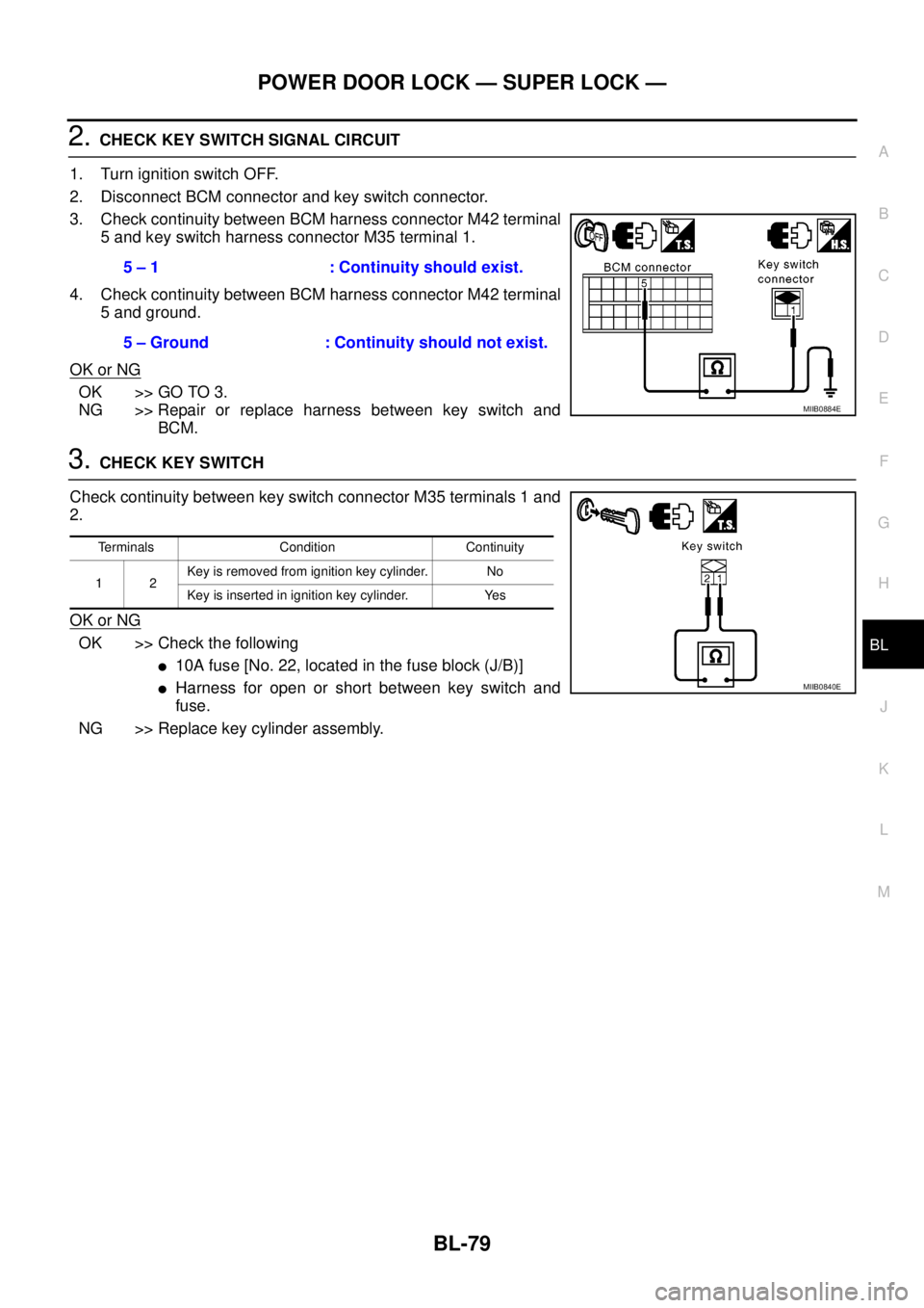
2.CHECK KEY SWITCH SIGNAL CIRCUIT
1. Turn ignition switch OFF.
2. Disconnect BCM connector and key switch connector.
3. Check continuity between BCM harness connector M42 terminal
5 and key switch harness connector M35 terminal 1.
4. Check continuity between BCM harness connector M42 terminal
5 and ground.
OK or NG
OK >> GO TO 3.
NG >> Repair or replace harness between key switch and
BCM.
3.CHECK KEY SWITCH
Check continuity between key switch connector M35 terminals 1 and
2.
OK or NG
OK >> Check the following
l10Afuse[No.22,locatedinthefuseblock(J/B)]
lHarness for open or short between key switch and
fuse.
NG >> Replace key cylinder assembly.5 – 1 : Continuity should exist.
5 – Ground : Continuity should not exist.
MIIB0884E
Terminals Condition Continuity
12Key is removed from ignition key cylinder. No
Key is inserted in ignition key cylinder. Yes
MIIB0840E
Page 675 of 3171

MULTI-REMOTE CONTROL SYSTEM
BL-91
C
D
E
F
G
H
J
K
L
MA
B
BL
System DescriptionEIS00DBE
INPUTS
Power is supplied at all times
lto BCM terminal 57
lthrough 50A fusible link (letterG, located in the fuse and fusible link box).
lto BCM terminal 41
lthrough 10A fuse [No. 21, located in the fuse block (J/B)].
When the key switch is ON (key is inserted in ignition key cylinder), power is supplied
lto BCM terminal 5
lthrough key switch terminals 2 and 1
lthrough 10A fuse [No. 22, located in the fuse block (J/B)].
When the ignition switch is ACC or ON, power is supplied
lto BCM terminal 4
lthrough 10A fuse [No. 4, located in the fuse block (J/B)].
When the ignition switch is ON or START, power is supplied
lto BCM terminal 3
lthrough 10A fuse [No. 1, located in the fuse block (J/B)].
When the front door switch (driver side) is ON (door is OPEN), ground is supplied
lto BCM terminal 15
lthrough front door switch (driver side) terminal 2
lto front door switch (driver side) case ground.
When the front door switch (passenger side) is ON (door is OPEN), ground is supplied
lto BCM terminal 14
lthrough front door switch (passenger side) terminal 2
lto front door switch (passenger side) case ground.
When the rear door switch LH is ON (door is OPEN), ground is supplied
lto BCM terminal 16
lthrough rear door switch LH terminal 2
lto rear door switch LH case ground.
When the rear door switch RH is ON (door is OPEN), ground is supplied
lto BCM terminal 12
lthrough rear door switch RH terminal 2
lto rear door switch RH case ground.
The multi-remote control system controls operation of the
lpowerdoorlock
linterior lamp and ignition keyhole illumination
lhazard reminder
lauto door lock operation
OPERATING PROCEDURE
Power Door Lock Operation
BCM receives a LOCK signal from keyfob. BCM locks all doors with input of LOCK signal from keyfob.
When an UNLOCK signal is sent from keyfob once, driver's door is unlocked.
Then, if an UNLOCK signal is sent from keyfob again within 5 seconds, all doors are unlocked.
Hazard Reminder
When the doors are locked or unlocked by keyfob, power is supplied to hazard warning lamp.
Hazard reminder does not operate if any door switches are ON (any doors are OPEN).
How to change hazard and horn reminder mode
Hazard and horn reminder can be changed using “WORK SUPPORT” mode in “MULTI ANSWER BACK SET”.
Refer toBL-102, "
CONSULT-II Function (BCM)".
Page 697 of 3171
MULTI-REMOTE CONTROL SYSTEM
BL-113
C
D
E
F
G
H
J
K
L
MA
B
BL
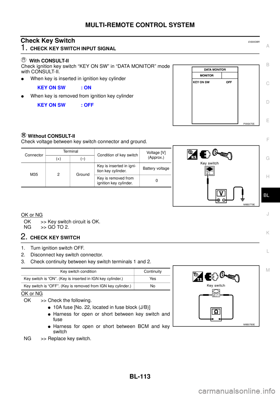
Check Key SwitchEIS00DBR
1.CHECK KEY SWITCH INPUT SIGNAL
With CONSULT-II
Check ignition key switch “KEY ON SW” in “DATA MONITOR” mode
with CONSULT-II.
lWhen key is inserted in ignition key cylinder
lWhen key is removed from ignition key cylinder
Without CONSULT-II
Check voltage between key switch connector and ground.
OK or NG
OK >> Key switch circuit is OK.
NG >> GO TO 2.
2.CHECK KEY SWITCH
1. Turn ignition switch OFF.
2. Disconnect key switch connector.
3. Check continuity between key switch terminals 1 and 2.
OK or NG
OK >> Check the following.
l10Afuse[No.22,locatedinfuseblock(J/B)]
lHarness for open or short between key switch and
fuse
lHarness for open or short between BCM and key
switch
NG >> Replace key switch.KEY ON SW : ON
KEY ON SW : OFF
PIIA6470E
ConnectorTerminal
Condition of key switchVo l ta g e [V ]
(Approx.)
(+) (–)
M35 2 GroundKey is inserted in igni-
tion key cylinder.Battery voltage
Key is removed from
ignition key cylinder.0
MIIB0779E
Key switch condition Continuity
Key switch is “ON”. (Key is inserted in IGN key cylinder.) Yes
Key switch is “OFF”. (Key is removed from IGN key cylinder.) No
MIIB0780E
Page 807 of 3171
BRAKE BOOSTER
BR-21
C
D
E
G
H
I
J
K
L
MA
B
BR
INSTALLATION
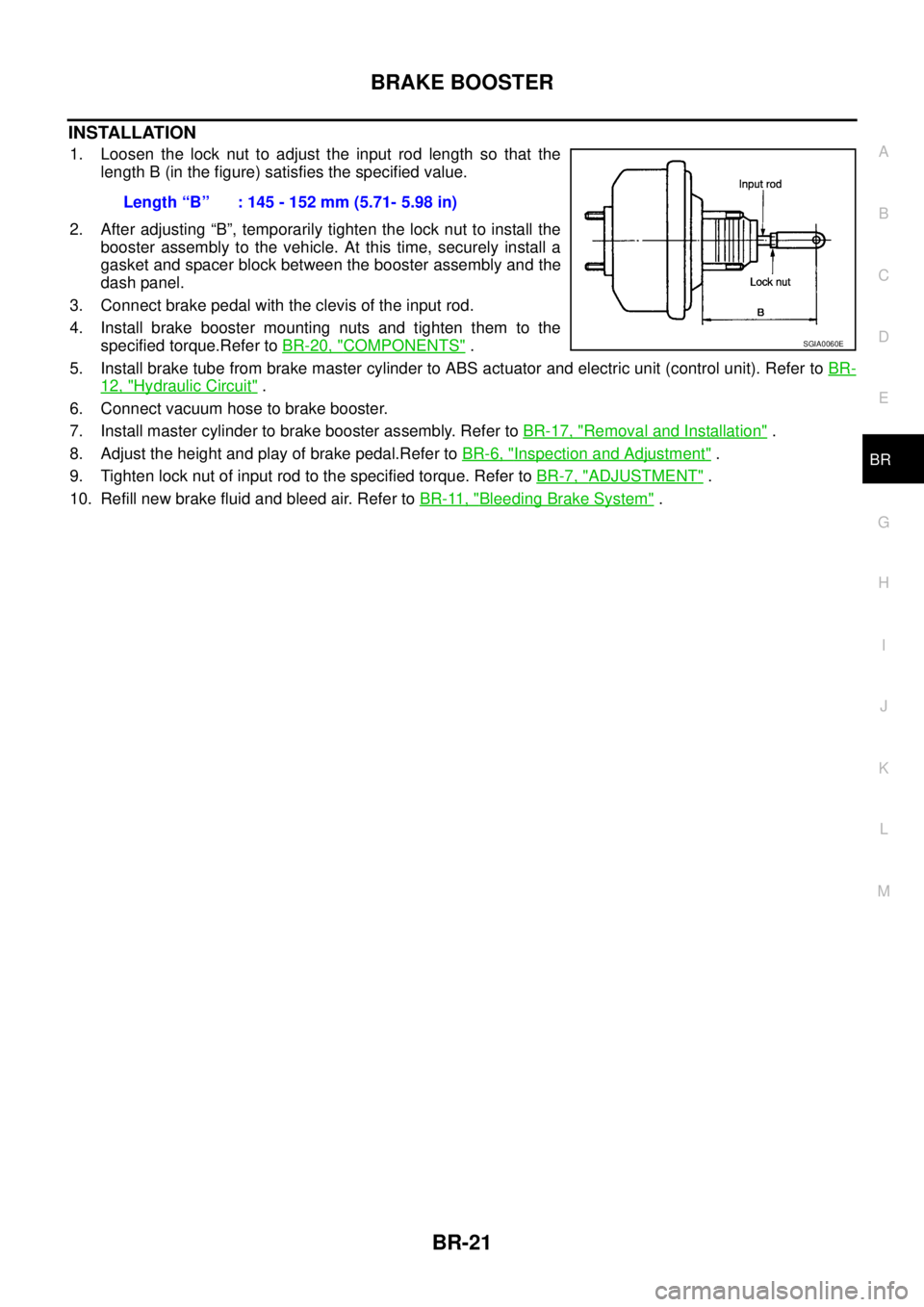
1. Loosen the lock nut to adjust the input rod length so that the
length B (in the figure) satisfies the specified value.
2. After adjusting “B”, temporarily tighten the lock nut to install the
booster assembly to the vehicle. At this time, securely install a
gasket and spacer block between the booster assembly and the
dash panel.
3. Connect brake pedal with the clevis of the input rod.
4. Install brake booster mounting nuts and tighten them to the
specified torque.Refer toBR-20, "
COMPONENTS".
5. Install brake tube from brake master cylinder to ABS actuator and electric unit (control unit). Refer toBR-
12, "Hydraulic Circuit".
6. Connect vacuum hose to brake booster.
7. Install master cylinder to brake booster assembly. Refer toBR-17, "
Removal and Installation".
8. Adjust the height and play of brake pedal.Refer toBR-6, "
Inspection and Adjustment".
9. Tighten lock nut of input rod to the specified torque. Refer toBR-7, "
ADJUSTMENT".
10. Refill new brake fluid and bleed air. Refer toBR-11, "
Bleeding Brake System". Length“B” :145-152mm(5.71-5.98in)
SGIA0060E
Page 813 of 3171
FRONT DISC BRAKE
BR-27
C
D
E
G
H
I
J
K
L
MA
B
BR
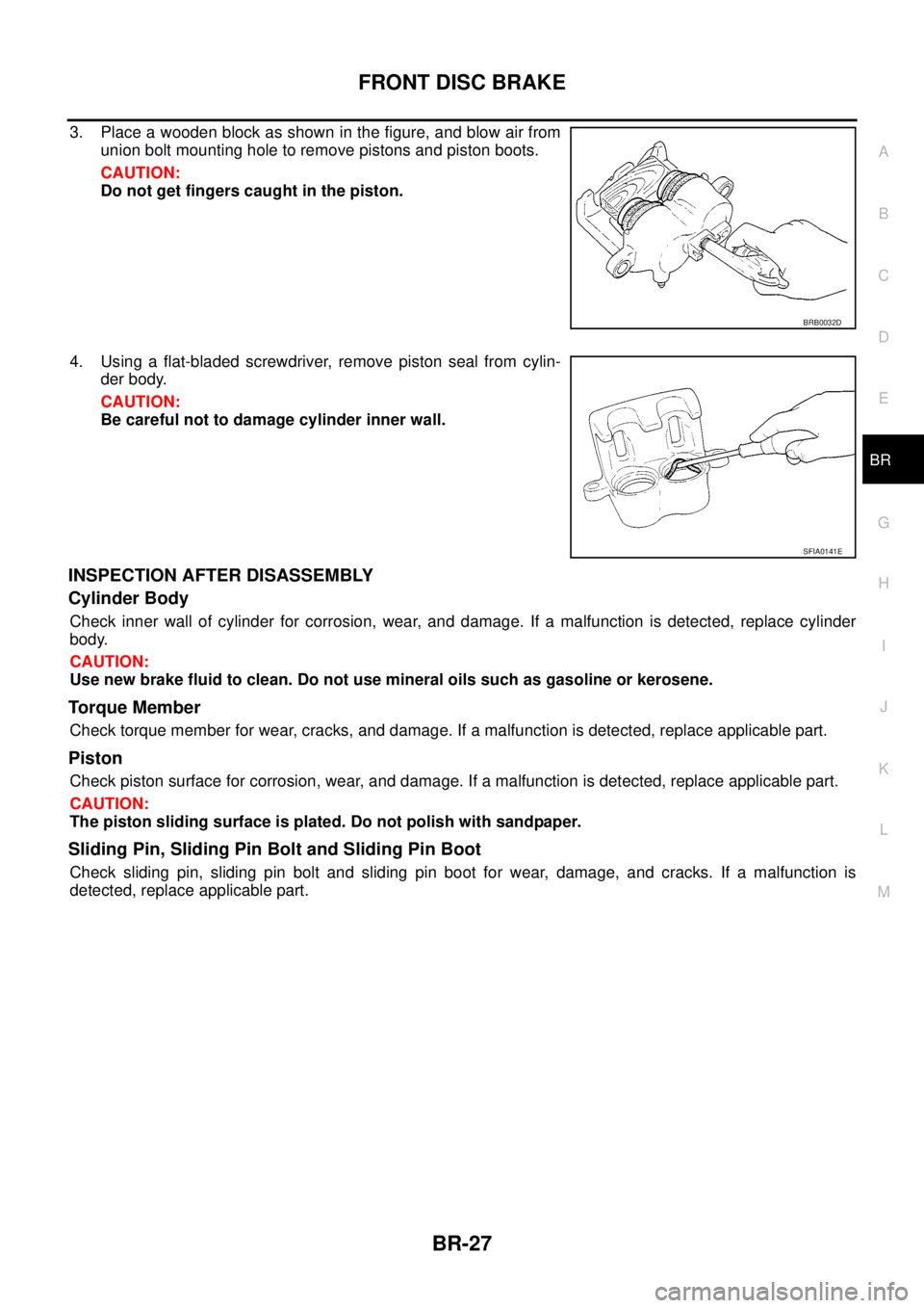
3. Place a wooden block as shown in the figure, and blow air from
union bolt mounting hole to remove pistons and piston boots.
CAUTION:
Do not get fingers caught in the piston.
4. Using a flat-bladed screwdriver, remove piston seal from cylin-
der body.
CAUTION:
Be careful not to damage cylinder inner wall.
INSPECTION AFTER DISASSEMBLY
Cylinder Body
Check inner wall of cylinder for corrosion, wear, and damage. If a malfunction is detected, replace cylinder
body.
CAUTION:
Use new brake fluid to clean. Do not use mineral oils such as gasoline or kerosene.
Torque Member
Check torque member for wear, cracks, and damage. If a malfunction is detected, replace applicable part.
Piston
Check piston surface for corrosion, wear, and damage. If a malfunction is detected, replace applicable part.
CAUTION:
The piston sliding surface is plated. Do not polish with sandpaper.
Sliding Pin, Sliding Pin Bolt and Sliding Pin Boot
Check sliding pin, sliding pin bolt and sliding pin boot for wear, damage, and cracks. If a malfunction is
detected, replace applicable part.
BRB0032D
SFIA0141E
Page 892 of 3171
CO-8
ENGINE COOLANT
DRAINING ENGINE COOLANT
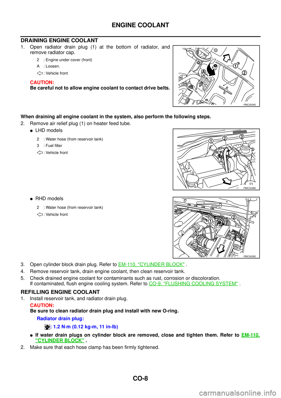
1. Open radiator drain plug (1) at the bottom of radiator, and
remove radiator cap.
CAUTION:
Be careful not to allow engine coolant to contact drive belts.
When draining all engine coolant in the system, also perform the following steps.
2. Remove air relief plug (1) on heater feed tube.
lLHD models
lRHD models
3. Open cylinder block drain plug. Refer toEM-110, "
CYLINDER BLOCK".
4. Remove reservoir tank, drain engine coolant, then clean reservoir tank.
5. Check drained engine coolant for contaminants such as rust, corrosion or discoloration.
If contaminated, flush engine cooling system. Refer toCO-9, "
FLUSHING COOLING SYSTEM".
REFILLING ENGINE COOLANT
1. Install reservoir tank, and radiator drain plug.
CAUTION:
Be sure to clean radiator drain plug and install with new O-ring.
lIf water drain plugs on cylinder block are removed, close and tighten them. Refer toEM-110,
"CYLINDER BLOCK".
2. Make sure that each hose clamp has been firmly tightened.
2 : Engine under cover (front)
A : Loosen.
: Vehicle front
PBIC3634E
2 : Water hose (from reservoir tank)
3 : Fuel filter
: Vehicle front
PBIC3348E
2 : Water hose (from reservoir tank)
: Vehicle front
PBIC3635E
Radiator drain plug:
: 1.2 N·m (0.12 kg-m, 11 in-lb)