steering NISSAN NAVARA 2005 Repair Workshop Manual
[x] Cancel search | Manufacturer: NISSAN, Model Year: 2005, Model line: NAVARA, Model: NISSAN NAVARA 2005Pages: 3171, PDF Size: 49.59 MB
Page 1 of 3171
MODELD40 SERIES
2005 NISSAN EUROPE S.A.S.
All rights reserved. No part of this Electronic Service Manual may be reproduced or stored in a retrieval system, or transmitted in any
form, or by any means, electronic, mechanical, photocopying, recording or otherwise, without the prior written permission of Nissan
Europe S.A.S., Paris, France.
A GENERAL INFORMATION
B ENGINE
C TRANSMISSION/TRANSAXLE
D DRIVELINE/AXLE
E SUSPENSION F BRAKES
G STEERING H RESTRAINTS
I BODY
J AIR CONDITIONER
K ELECTRICAL
L MAINTENANCE
M INDEXGI General Information
EM Engine Mechanical
LU Engine Lubrication System
CO Engine Cooling System
EC Engine Control System
FL Fuel System
EX Exhaust System
ACC Accelerator Control System
CL Clutch
MTManualTransmission
AT Automatic Transmission
TF Transfer
PR Propeller Shaft
FFD Front Final Drive
RFD Rear Final Drive
FAX Front Axle
RAX Rear Axle
FSU Front Suspension
RSU Rear Suspension
WT Road Wheels & Tires
BR Brake System
PB Parking Brake System
BRC Brake Control System
PS Power Steering System
SB Seat Belts
SRS Supplemental Restraint System (SRS)
BL Body, Lock & Security System
GW Glasses, Window System & Mirrors
RF Roof
EI Exterior & Interior
IP Instrument Panel
SE Seat
ATC Automatic Air Conditioner
MTC Manual Air Conditioner
SC Starting & Charging System
LT Lighting System
DI Driver Information System
WW Wiper, Washer & Horn
BCS Body Control System
LAN LAN System
AV Audio, Visual & Telephone System
ACS Auto Cruise Control System
PG Power Supply, Ground & Circuit Elements
MA Maintenance
IDX Alphabetical Index
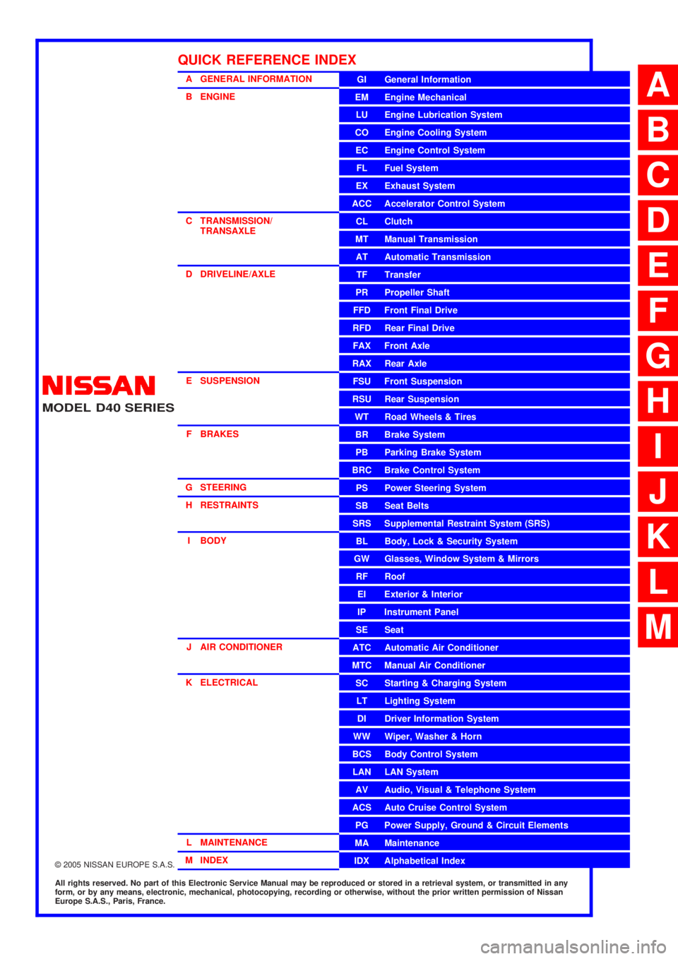
QUICK REFERENCE INDEX
A
B
C
D
E
F
G
H
I
J
K
L
M
Page 460 of 3171
ATC-126
HEATER & COOLING UNIT ASSEMBLY
Removal and Installation
EJS006C9
REMOVAL
1. Discharge the refrigerant from the A/C system. Refer toATC-138, "Discharging Refrigerant".
2. Drain the coolant from the engine cooling system. Refer toCO-8, "
DRAINING ENGINE COOLANT".
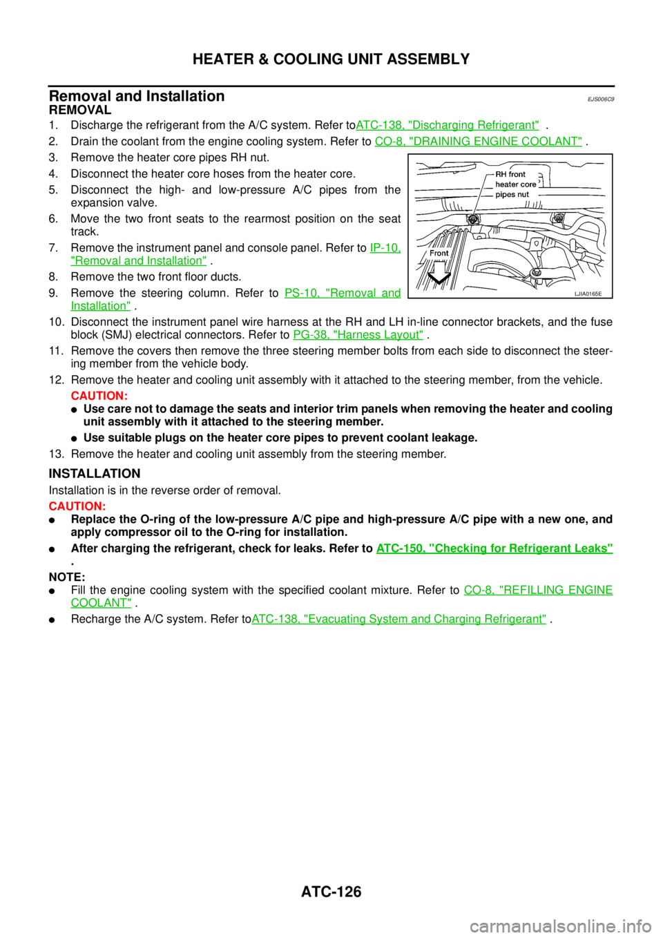
3. Remove the heater core pipes RH nut.
4. Disconnect the heater core hoses from the heater core.
5. Disconnect the high- and low-pressure A/C pipes from the
expansion valve.
6. Move the two front seats to the rearmost position on the seat
track.
7. Remove the instrument panel and console panel. Refer toIP-10,
"Removal and Installation".
8. Remove the two front floor ducts.
9. Remove the steering column. Refer toPS-10, "
Removal and
Installation".
10. Disconnect the instrument panel wire harness at the RH and LH in-line connector brackets, and the fuse
block (SMJ) electrical connectors. Refer toPG-38, "
Harness Layout".
11. Remove the covers then remove the three steering member bolts from each side to disconnect the steer-
ing member from the vehicle body.
12. Remove the heater and cooling unit assembly with it attached to the steering member, from the vehicle.
CAUTION:
lUse care not to damage the seats and interior trim panels when removing the heater and cooling
unit assembly with it attached to the steering member.
lUse suitable plugs on the heater core pipes to prevent coolant leakage.
13. Remove the heater and cooling unit assembly from the steering member.
INSTALLATION
Installation is in the reverse order of removal.
CAUTION:
lReplace the O-ring of the low-pressure A/C pipe and high-pressure A/C pipe with a new one, and
apply compressor oil to the O-ring for installation.
lAfter charging the refrigerant, check for leaks. Refer toATC-150, "Checking for Refrigerant Leaks"
.
NOTE:
lFill the engine cooling system with the specified coolant mixture. Refer toCO-8, "REFILLING ENGINE
COOLANT".
lRecharge the A/C system. Refer toATC-138, "Evacuating System and Charging Refrigerant".
LJIA0165E
Page 463 of 3171
INTAKE DOOR MOTOR
ATC-129
C
D
E
F
G
H
I
K
L
MA
B
AT C
INTAKE DOOR MOTORPFP:27730
ComponentsEJS006CD
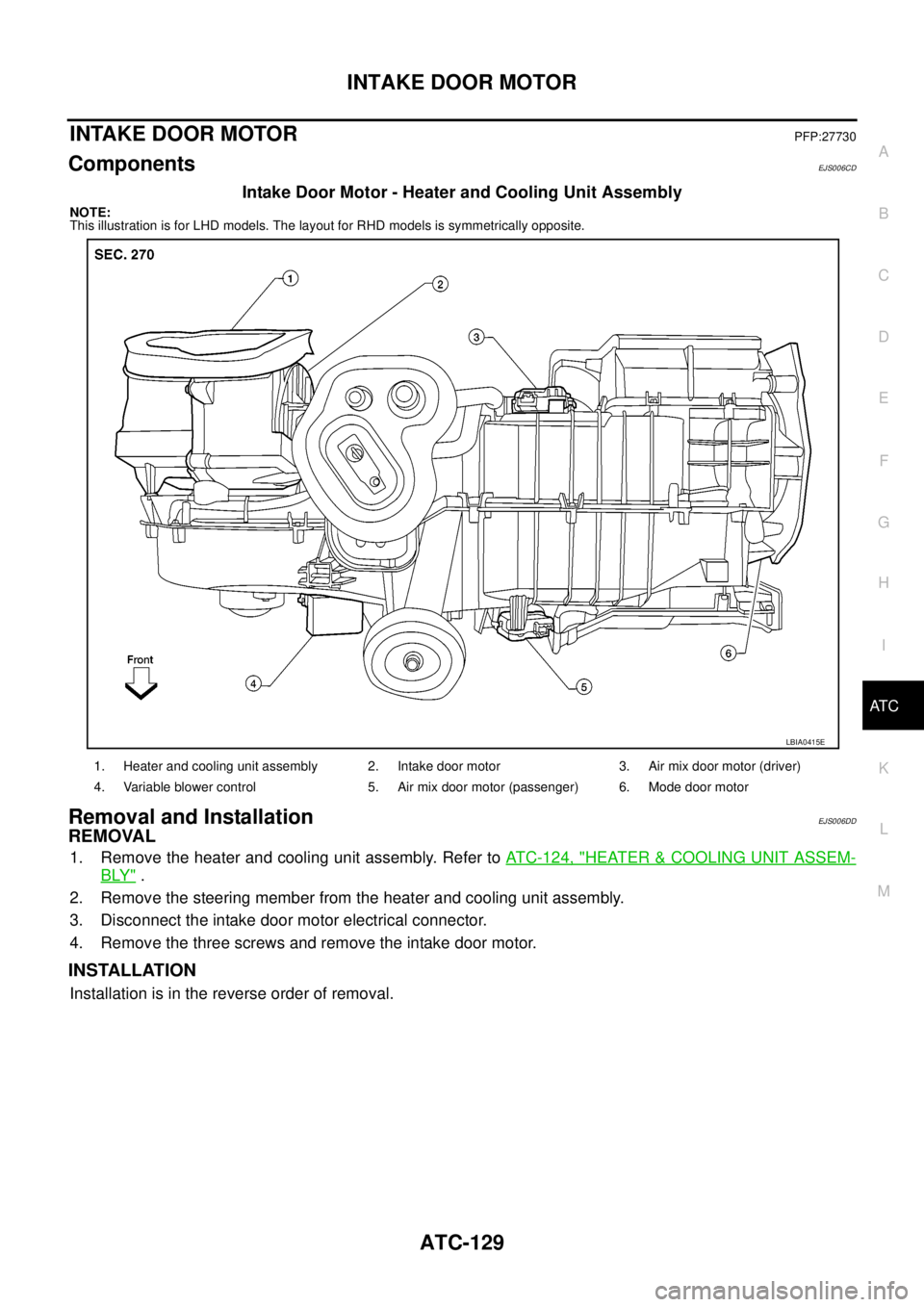
Intake Door Motor - Heater and Cooling Unit Assembly
NOTE:
This illustration is for LHD models. The layout for RHD models is symmetrically opposite.
Removal and InstallationEJS006DD
REMOVAL
1. Remove the heater and cooling unit assembly. Refer toATC-124, "HEATER&COOLING UNIT ASSEM-
BLY".
2. Remove the steering member from the heater and cooling unit assembly.
3. Disconnect the intake door motor electrical connector.
4. Remove the three screws and remove the intake door motor.
INSTALLATION
Installation is in the reverse order of removal.
1. Heater and cooling unit assembly 2. Intake door motor 3. Air mix door motor (driver)
4. Variable blower control 5. Air mix door motor (passenger) 6. Mode door motor
LBIA0415E
Page 465 of 3171
AIR MIX DOOR MOTOR
ATC-131
C
D
E
F
G
H
I
K
L
MA
B
AT C
AIR MIX DOOR MOTORPFP:27732
ComponentsEJS006CF
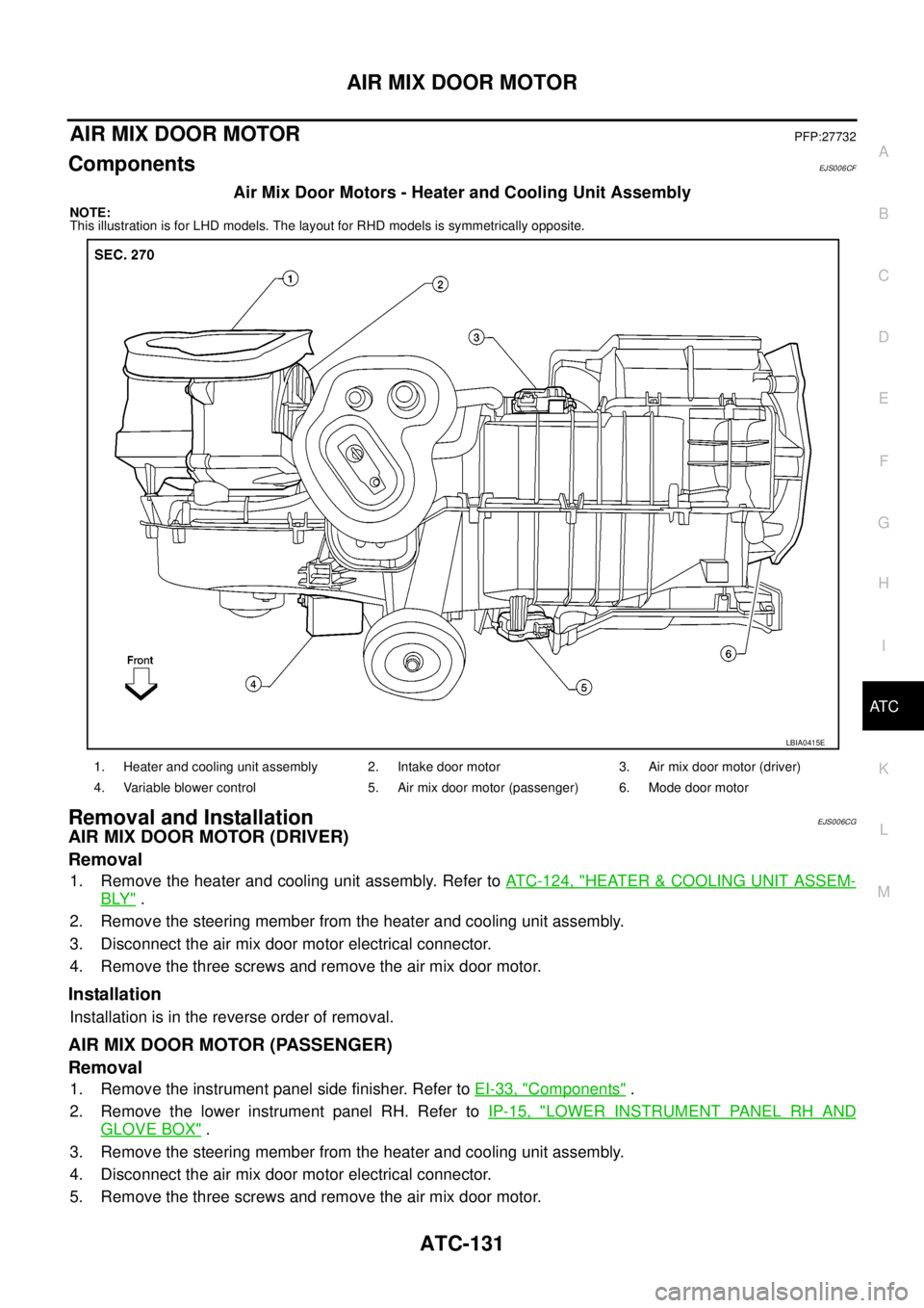
Air Mix Door Motors - Heater and Cooling Unit Assembly
NOTE:
This illustration is for LHD models. The layout for RHD models is symmetrically opposite.
Removal and InstallationEJS006CG
AIR MIX DOOR MOTOR (DRIVER)
Removal
1. Remove the heater and cooling unit assembly. Refer toATC-124, "HEATER&COOLING UNIT ASSEM-
BLY".
2. Remove the steering member from the heater and cooling unit assembly.
3. Disconnect the air mix door motor electrical connector.
4. Remove the three screws and remove the air mix door motor.
Installation
Installation is in the reverse order of removal.
AIR MIX DOOR MOTOR (PASSENGER)
Removal
1. Remove the instrument panel side finisher. Refer toEI-33, "Components".
2. Remove the lower instrument panel RH. Refer toIP-15, "
LOWER INSTRUMENT PANEL RH AND
GLOVE BOX".
3. Remove the steering member from the heater and cooling unit assembly.
4. Disconnect the air mix door motor electrical connector.
5. Remove the three screws and remove the air mix door motor.
1. Heater and cooling unit assembly 2. Intake door motor 3. Air mix door motor (driver)
4. Variable blower control 5. Air mix door motor (passenger) 6. Mode door motor
LBIA0415E
Page 489 of 3171

AV-1
AUDIO-VISUAL SYSTEM
K ELECTRICAL
CONTENTS
C
D
E
F
G
H
I
J
L
M
SECTIONAV
A
B
AV
AUDIO-VISUAL SYSTEM
PRECAUTIONS .......................................................... 3
Precautions for Supplemental Restraint System
(SRS)“AIRBAG”and“SEATBELTPRE-TEN-
SIONER” .................................................................. 3
Wiring Diagrams and Trouble Diagnosis .................. 3
SYSTEM DESCRIPTION ............................................ 4
System Functions ..................................................... 4
AUDIO ................................................................... 4
NATS AUDIO LINK (WITHOUT NAVIGATION
SYSTEM) .............................................................. 4
VEHICLE INFORMATION SYSTEM ..................... 5
NAVIGATION SYSTEM ......................................... 5
HANDS-FREE PHONE ......................................... 7
Component Description ............................................ 8
AUDIO UNIT ......................................................... 8
NAVI CONTROL UNIT .......................................... 8
GPS ANTENNA .................................................... 9
DISPLAY UNIT ...................................................... 9
AV SWITCH .......................................................... 9
Component Parts Location ..................................... 10
Location Of Antenna .............................................. 10
Schematic — AUDIO — / With 1CD Player Type... 12
Wiring Diagram — AUDIO — / With 1CD Player Type
... 13
Schematic — AUDIO — / With 6CD Player Type... 16
Wiring Diagram — AUDIO — / With 6CD Player Type
... 17
Schematic — NAVI — ............................................ 20
Wiring Diagram — NAVI — .................................... 21
Schematic — NAVI — / COMM .............................. 28
Wiring Diagram — NAVI — / COMM ...................... 29
Wiring Diagram — TELEPHONE (PRE WIRE) —
/ Without NAVI ........................................................ 32
CAN Communication .............................................. 33
SYSTEM DESCRIPTION .................................... 33
TERMINALS AND REFERENCE VALUE FOR CON-
TROL UNIT ............................................................... 34
Audio Unit (1CD Player Type) ................................ 34
Audio Unit (6CD Player Type) Without NAVI .......... 35Audio Unit (With NAVI) ........................................... 37
NAVI Control Unit ................................................... 38
Display Unit ............................................................ 41
DIAGNOSIS SYSTEM ............................................... 44
Navigation System Diagnosis Function .................. 44
On Bord Self-Diagnosis Function ........................... 44
DESCRIPTION .................................................... 44
DIAGNOSIS ITEM ............................................... 44
OPERATION PROCEDURE ................................ 45
Self Diagnosis Mode ............................................... 46
ERROR DETECTION RANGE OF SELF-DIAG-
NOSIS MODE ..................................................... 47
DIAGNOSIS RESULTS ....................................... 47
Confirmation/Adjustment Mode .............................. 48
SCREEN TROUBLE DIAGNOSIS ...................... 49
VEHICLE SIGNALS ............................................ 49
SPEAKER TEST ................................................. 50
NAVIGATION ....................................................... 50
ERROR HISTORY ............................................... 51
VEHICLE CAN DIAGNOSIS ............................... 53
AV COMM DIAGNOSIS ....................................... 54
HANDSFREE PHONE ........................................ 54
BLUETOOTH ....................................................... 54
DELETE UNIT CONNECTION LOG ................... 55
CONSULT-II Functions ........................................... 56
CONSULT-II FUNCTIONS ................................... 56
CONSULT-II BASIC OPERATION PROCEDURE
... 56
SELF-DIAG RESULTS ........................................ 56
DATA MONITOR ................................................. 58
AV COMM MONITOR .......................................... 59
ECU PART NUMBER .......................................... 60
TROUBLE DIAGNOSIS ............................................ 61
Navigation System .................................................. 61
RGB Image ............................................................. 61
Voice Activated Control System ............................. 62
Steering Wheel Switch ............................................ 63
Component Parts Inspection .................................. 63
STEERING WHEEL SWITCH UNIT INSPEC-
Page 494 of 3171
AV-6
SYSTEM DESCRIPTION
Map-Matching
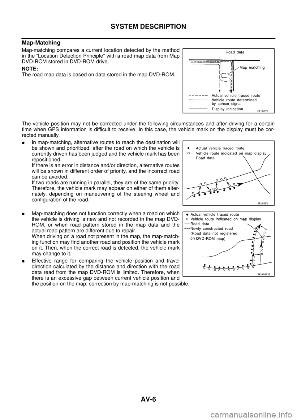
Map-matching compares a current location detected by the method
in the “Location Detection Principle” with a road map data from Map
DVD-ROM stored in DVD-ROM drive.
NOTE:
TheroadmapdataisbasedondatastoredinthemapDVD-ROM.
The vehicle position may not be corrected under the following circumstances and after driving for a certain
time when GPS information is difficult to receive. In this case, the vehicle mark on the display must be cor-
rected manually.
lIn map-matching, alternative routes to reach the destination will
be shown and prioritized, after the road on which the vehicle is
currently driven has been judged and the vehicle mark has been
repositioned.
If there is an error in distance and/or direction, alternative routes
will be shown in different order of priority, and the incorrect road
can be avoided.
If two roads are running in parallel, they are of the same priority.
Therefore, the vehicle mark may appear on either of them alter-
nately, depending on maneuvering of the steering wheel and
configuration of the road.
lMap-matching does not function correctly when a road on which
the vehicle is driving is new and not recorded in the map DVD-
ROM, or when road pattern stored in the map data and the
actual road pattern are different due to repair.
When driving on a road not present in the map, the map-match-
ing function may find another road and position the vehicle mark
on it. Then, when the correct road is detected, the vehicle mark
may change to it.
lEffective range for comparing the vehicle position and travel
direction calculated by the distance and direction with the road
data read from the map DVD-ROM is limited. Therefore, when
there is an excessive gap between current vehicle position and
the position on the map, correction by map-matching is not possible.
SEL685V
SEL686V
SKIA0613E
Page 496 of 3171
AV-8
SYSTEM DESCRIPTION
Component Description
EKS00Q5Y
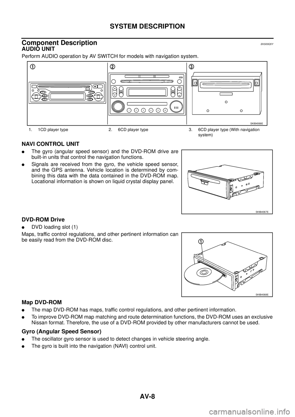
AUDIO UNIT
Perform AUDIO operation by AV SWITCH for models with navigation system.
NAVI CONTROL UNIT
lThe gyro (angular speed sensor) and the DVD-ROM drive are
built-in units that control the navigation functions.
lSignals are received from the gyro, the vehicle speed sensor,
and the GPS antenna. Vehicle location is determined by com-
bining this data with the data contained in the DVD-ROM map.
Locational information is shown on liquid crystal display panel.
DVD-ROM Drive
lDVD loading slot (1)
Maps, traffic control regulations, and other pertinent information can
be easily read from the DVD-ROM disc.
Map DVD-ROM
lThe map DVD-ROM has maps, traffic control regulations, and other pertinent information.
lTo improve DVD-ROM map matching and route determination functions, the DVD-ROM uses an exclusive
Nissan format. Therefore, the use of a DVD-ROM provided by other manufacturers cannot be used.
Gyro (Angular Speed Sensor)
lThe oscillator gyro sensor is used to detect changes in vehicle steering angle.
lThe gyro is built into the navigation (NAVI) control unit.
1. 1CD player type 2. 6CD player type 3. 6CD player type (With navigation
system)
SKIB4066E
SKIB4067E
SKIB4068E
Page 532 of 3171

AV-44
DIAGNOSIS SYSTEM
DIAGNOSIS SYSTEM
PFP:00000
Navigation System Diagnosis FunctionEKS00Q6H
lThere are 2 diagnosis functions (on board diagnosis and diagnosis using CONSULT-II), and it is neces-
sary to use them properly according to the condition. If the on board diagnosis starts, perform diagnosis
with on board diagnosis. If the on board diagnosis does not start (the cause being that the system is not
started, the switch operation is not activated, etc.), perform diagnosis using CONSULT-II.
lAt on board diagnosis, the NAVI control unit diagnosis function starts by switch operation and the NAVI
control unit performs the diagnosis for each unit of system.
lAt diagnosis using CONSULT-II, the NAVI control unit diagnosis function starts by the communication
between CONSULT-II and NAVI control unit, and the NAVI control unit performs the diagnosis for each
unit of system.
On Bord Self-Diagnosis FunctionEKS00Q6I
DESCRIPTION
lThe on board diagnosis function has a self-diagnosis mode for performing trouble diagnosis automatically
and a Confirmation/Adjustment mode for operating manually.
lSelf-diagnosis mode performs the diagnosis at NAVI control unit, connections between each unit that
composes the system, and connections between NAVI control unit and GPS antenna. It displays the
results on the display.
lConfirmation/Adjustment mode is used to monitor the vehicle signals requiring operation and judgement
by a technician (malfunctions that cannot be automatically judged by the system), the confirmation/adjust-
ment of setting value, the error history of system, and the communication condition of system.
DIAGNOSIS ITEM
Mode Description
Self Diagnosis
lNAVI control unit diagnosis (DVD-ROM drive will not be diagnosed when
no map DVD-ROM is in it.)
lThe connection diagnosis between NAVI control unit and GPS antenna
and the connection diagnosis between NAVI control unit and each unit
can be performed.
Confirma-
tion/Adjust-
mentDisplay DiagnosisThe tint can be confirmed by the color spectrum bar display. The shading
of color can be confirmed by the gradation bar display.
Vehicle SignalsDiagnosis of signals can be performed for vehicle speed, parking brake,
lights, ignition (ignition switch), and reverse.
Speaker Test The connection of a speaker can be confirmed by test tone.
NavigationSteering Angle
AdjustmentWhen there is a difference between the actual turning angle and the vehi-
cle mark turning angle, it can be adjusted.
Speed CalibrationWhen there is a difference between the current location mark and the
actual location, it can be adjusted.
Error HistoryThe system malfunction and its frequency that occurred in the past are dis-
played. When the malfunctioning item is selected, the time and place that
the selected malfunction last occurred are displayed.
Vehicle CAN Diagnosis The transmitting/receiving of CAN communication can be monitored.
AV COMM DiagnosisThe communication condition of each unit that composes the system can
be monitored.
Handsfree PhoneEach setting of hands-free volume adjustment, voice microphone test,
delete hands-free memory can be performed.
Bluetooth Passkey and device name can be confirmed/changed.
Delete Unit Commection Log The connection history and error history of unit can be deleted.
Page 538 of 3171
AV-50
DIAGNOSIS SYSTEM
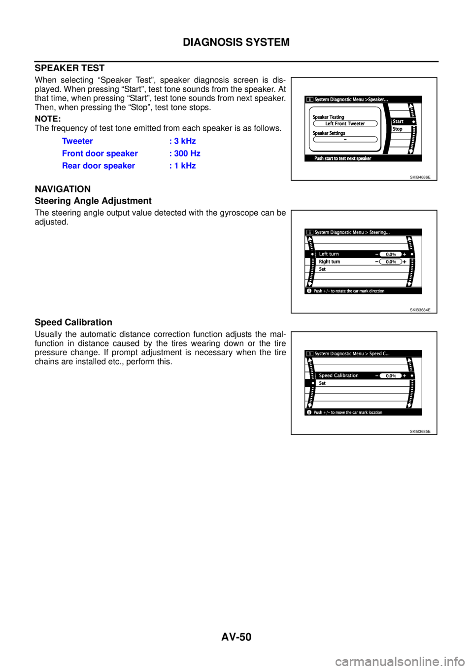
SPEAKER TEST
When selecting “Speaker Test”, speaker diagnosis screen is dis-
played. When pressing “Start”, test tone sounds from the speaker. At
that time, when pressing “Start”, test tone sounds from next speaker.
Then, when pressing the “Stop”, test tone stops.
NOTE:
The frequency of test tone emitted from each speaker is as follows.
NAVIGATION
Steering Angle Adjustment
The steering angle output value detected with the gyroscope can be
adjusted.
Speed Calibration
Usually the automatic distance correction function adjusts the mal-
function in distance caused by the tires wearing down or the tire
pressure change. If prompt adjustment is necessary when the tire
chains are installed etc., perform this.Tw e e t e r : 3 k H z
Front door speaker : 300 Hz
Rear door speaker : 1 kHz
SKIB4686E
SKIB3684E
SKIB3685E
Page 547 of 3171
DIAGNOSIS SYSTEM
AV-59
C
D
E
F
G
H
I
J
L
MA
B
AV
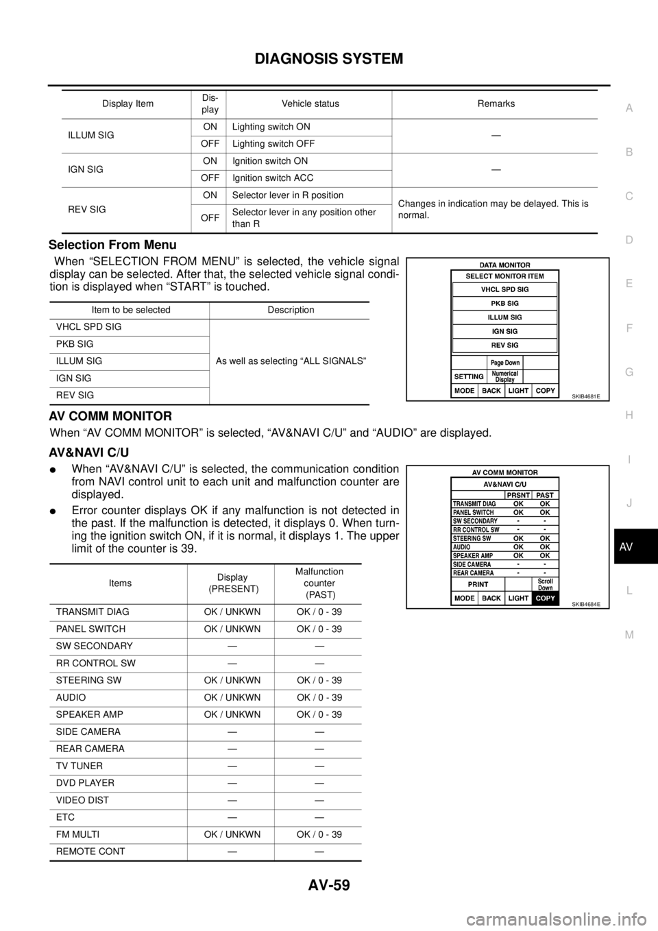
Selection From Menu
When “SELECTION FROM MENU” is selected, the vehicle signal
display can be selected. After that, the selected vehicle signal condi-
tion is displayed when “START” is touched.
AV C O M M M O N I T O R
When “AV COMM MONITOR” is selected, “AV&NAVI C/U” and “AUDIO” are displayed.
AV&NAVI C/U
lWhen “AV&NAVI C/U” is selected, the communication condition
from NAVI control unit to each unit and malfunction counter are
displayed.
lError counter displays OK if any malfunction is not detected in
the past. If the malfunction is detected, it displays 0. When turn-
ing the ignition switch ON, if it is normal, it displays 1. The upper
limitofthecounteris39.
ILLUM SIGON Lighting switch ON
—
OFF Lighting switch OFF
IGN SIGON Ignition switch ON
—
OFF Ignition switch ACC
REV SIGON Selector lever in R position
Changes in indication may be delayed. This is
normal.
OFFSelector lever in any position other
than R Display ItemDis-
playVehicle status Remarks
Item to be selected Description
VHCL SPD SIG
As well as selecting “ALL SIGNALS” PKB SIG
ILLUM SIG
IGN SIG
REV SIG
SKIB4681E
ItemsDisplay
(PRESENT)Malfunction
counter
(PAST)
TRANSMIT DIAG OK / UNKWN OK / 0 - 39
PANEL SWITCH OK / UNKWN OK / 0 - 39
SW SECONDARY — —
RR CONTROL SW — —
STEERING SW OK / UNKWN OK / 0 - 39
AUDIO OK / UNKWN OK / 0 - 39
SPEAKER AMP OK / UNKWN OK / 0 - 39
SIDE CAMERA — —
REAR CAMERA — —
TV TUNER — —
DVD PLAYER — —
VIDEO DIST — —
ETC — —
FM MULTI OK / UNKWN OK / 0 - 39
REMOTE CONT — —
SKIB4684E