roof NISSAN NOTE 2016 Service Owner's Manual
[x] Cancel search | Manufacturer: NISSAN, Model Year: 2016, Model line: NOTE, Model: NISSAN NOTE 2016Pages: 3641, PDF Size: 28.72 MB
Page 978 of 3641
![NISSAN NOTE 2016 Service Owners Manual BACK DOORDLK-289
< REMOVAL AND INSTALLATION > [WITHOUT INTELLIGENT KEY SYSTEM]
C
D
E
F
G H
I
J
L
M A
B
DLK
N
O P
Check the clearance and the surface height between back door and each part by visual in NISSAN NOTE 2016 Service Owners Manual BACK DOORDLK-289
< REMOVAL AND INSTALLATION > [WITHOUT INTELLIGENT KEY SYSTEM]
C
D
E
F
G H
I
J
L
M A
B
DLK
N
O P
Check the clearance and the surface height between back door and each part by visual in](/img/5/57363/w960_57363-977.png)
BACK DOORDLK-289
< REMOVAL AND INSTALLATION > [WITHOUT INTELLIGENT KEY SYSTEM]
C
D
E
F
G H
I
J
L
M A
B
DLK
N
O P
Check the clearance and the surface height between back door and each part by visual inspection and tactile
feel. If the clearance and the surface height are out of specification, adjust them according to the adjustment
procedure.
Unit: mm (in)
1. Loosen back door hinge nuts (door side).
2. Lift up back door approximately 100 – 150 mm (3.94 – 5.91 in) height then close it lightly and check that it
is engaged firmly with back door closed.
3. Check the clearance and surface height and adjust back door as necessary.
4. Tighten back door hinge nuts to specified torque.
CAUTION:
• After installation, check back door open/close, lock/ unlock operation.
• Check back door hinge rotating po int for poor lubrication. If necessary, apply a suitable multi-pur-
pose grease.
• After adjusting, apply touch-up paint (body color) to the head of rear door hinge bolts and nuts.
BACK DOOR STRIKER
BACK DOOR STRIKER : Removal and InstallationINFOID:0000000012430258
REMOVAL
1. Remove back door kicking plate using a suitable tool.
2. Remove bolts and back door striker.
INSTALLATION
Installation is in the reverse order of removal.
CAUTION:
• Do not reuse back door striker bolts.
• After installation, check back door open/close, lock/ unlock operation.
• After installation, perfor m the back door assembly adjustment procedure. Refer to DLK-288, "
BACK
DOOR ASSEMBLY : Adjustment".
BACK DOOR STRIKER : AdjustmentINFOID:0000000012430259
DOOR STRIKER ADJUSTMENT
1. Loosen door striker bolts.
2. Adjust door striker so that it becomes parallel with back door
lock insertion direction.
3. Tighten door striker bolts to specification. Refer to DLK-286, "
Exploded View".
PortionSection Item Measurement Standard
Back door panel – Roof panel A – A H
Clearance 6.0 ± 1.0 (0.24 ± 0.04)
I Surface height 0.0 +0.5, -1.5 (0.00 +0.02, -0.06)
Rear combination lamp – Back door panel B – B J
Clearance 5.0 ± 2.0 (0.20 ± 0.08)
K Surface height -2.0 ± 2.0 (-0.08 ± 0.08)
Rear bumper fascia – Back-door panel C – CL C
le a ra n ce 5 .0 ± 2.0 (0.20 ± 0.08)
M Surface height 0.0 +0.5, -2.0 (0.0 +0.02, -0.08)
D – D M Clearance7.0 ± 2.0 (0.28 ± 0.08)
PIIB2804J
Revision: August 2015 2016 Versa Note
cardiagn.com
Page 1156 of 3641
![NISSAN NOTE 2016 Service Owners Manual STRUCTURE AND OPERATIONEC-29
< SYSTEM DESCRIPTION > [HR16DE]
C
D
E
F
G H
I
J
K L
M A
EC
NP
O
On Board Refueling Vapor Recovery (ORVR)INFOID:0000000012431306
From the beginning of refueling, the air an NISSAN NOTE 2016 Service Owners Manual STRUCTURE AND OPERATIONEC-29
< SYSTEM DESCRIPTION > [HR16DE]
C
D
E
F
G H
I
J
K L
M A
EC
NP
O
On Board Refueling Vapor Recovery (ORVR)INFOID:0000000012431306
From the beginning of refueling, the air an](/img/5/57363/w960_57363-1155.png)
STRUCTURE AND OPERATIONEC-29
< SYSTEM DESCRIPTION > [HR16DE]
C
D
E
F
G H
I
J
K L
M A
EC
NP
O
On Board Refueling Vapor Recovery (ORVR)INFOID:0000000012431306
From the beginning of refueling, the air and vapor insi
de the fuel tank go through refueling EVAP vapor cut
valve and EVAP/ORVR line to the EVAP canister. The v apor is absorbed by the EVAP canister and the air is
released to the atmosphere.
When the refueling has reached the full level of the fuel tank, the refueling EVAP vapor cut valve is closed and
refueling is stopped because of auto shut-off. The vapor which was absorbed by the EVAP canister is purged
during driving.
WARNING:
When conducting inspectio ns below, be sure to observe the following:
• Put a “CAUTION: FLAMMABL E” sign in workshop.
• Do not smoke while servicing fuel system. Keep open flames and sparks away from work area.
• Be sure to furnish the workshop with a CO
2 fire extinguisher.
CAUTION:
• Before removing fuel line parts, carry out the following procedures:
- Put drained fuel in an explosion-proof containe r and put lid on securely.
- Release fuel pressure from fuel line. Refer to EC-137, "
Work Procedure".
- Disconnect battery ground cable.
• Always replace O-ring when the fu el gauge retainer is removed.
• Do not kink or twist hose and tube when they are installed.
• Do not tighten hose and clamps excessively to avoid damaging hoses.
• After installation, run engine and check for fuel leaks at connection.
• Do not attempt to top off the fuel tank after the fuel pump nozzle shuts off automatically.
Continued refueling may cause fuel overflow, resulting in fuel spray and possibly a fire.
JMBIA1930GB
Revision: August 2015 2016 Versa Note
cardiagn.com
Page 1768 of 3641
EXT-1
BODY EXTERIOR, DOORS, ROOF & VEHICLE SECURITY
C
DE
F
G H
I
J
L
M
SECTION EXT
A
B
EXT
N
O P
CONTENTS
EXTERIOR
PRECAUTION ....... ........................................3
PRECAUTIONS .............................................. .....3
Precaution for Supplemental Restraint System
(SRS) "AIR BAG" and "SEAT BELT PRE-TEN-
SIONER" ............................................................. ......
3
Procedure without Cowl Top Cover .......................3
Precaution for Work ..................................................3
PREPARATION ............................................5
PREPARATION .............................................. .....5
Special Service Tools ........................................ ......5
Commercial Service Tools .......................................5
CLIP LIST ............................................................6
Descriptions for Clips ................................................6
SYSTEM DESCRIPTION .............................10
COMPONENT PARTS ................................... ....10
ACTIVE GRILLE SHUTTER SYSTEM ......................10
ACTIVE GRILLE SHUTTER SYSTEM :
Component Parts Location ................................ ....
10
ACTIVE GRILLE SHUTTER SYSTEM : Active
grille shutter ......................................................... ....
10
SYSTEM .............................................................11
ACTIVE GRILLE SHUTTER SYSTEM ......................11
ACTIVE GRILLE SHUTTER SYSTEM : System
Diagram ............................................................... ....
11
ACTIVE GRILLE SHUTTER SYSTEM : System
Description ..............................................................
11
WIRING DIAGRAM ......................................13
ACTIVE GRILLE SHUTTER ...............................13
Wiring Diagram ................................................... ....13
SYMPTOM DIAGNOSIS ..............................17
SQUEAK AND RATTLE TROUBLE DIAG-
NOSES ..............................................................
17
Work Flow ............................................................ ....17
Generic Squeak and Rattle Troubleshooting ...........18
Diagnostic Worksheet ..............................................21
REMOVAL AND INSTALLATION ...............23
FRONT BUMPER ..............................................23
Exploded View ..................................................... ....23
Removal and Installation .........................................24
REAR BUMPER ................................................28
Exploded View .........................................................28
Removal and Installation .........................................29
FRONT GRILLE ................................................32
Exploded View .........................................................32
Removal and Installation .........................................32
ACTIVE GRILLE SHUTTER .............................33
Exploded View .........................................................33
Removal and Installation .........................................33
FRONT SPOILER ..............................................34
Exploded View .........................................................34
Removal and Installation .........................................35
COWL TOP .......................................................36
Exploded View .........................................................36
Removal and Installation .........................................37
FENDER PROTECTOR ....................................38
Exploded View .........................................................38
Removal and Installation .........................................38
UNDER COVER ................................................39
FRONT UNDER COVER ........................................ ....39
FRONT UNDER COVER : Exploded View ..............39
FRONT UNDER COVER : Removal and Installa-
tion ...........................................................................
39
Exploded View .........................................................40
Revision: August 2015 2016 Versa Note
cardiagn.com
Page 1769 of 3641

EXT-2
FLOOR UNDER COVER ...........................................40
FLOOR UNDER COVER : Removal and Installa-
tion ..........................................................................
40
REAR WIND DEFLECTOR .................................... ...41
REAR WIND DEFLECTOR : Removal and Instal-
lation .......................................................................
41
ROOF SIDE MOLDING ......................................42
Exploded View ..................................................... ...42
Removal and Installation ........................................42
DOOR SASH TAPE ...........................................44
Exploded View ..................................................... ...44
Removal and Installation .........................................45
DOOR OUTSIDE MOLDING .............................46
Exploded View ..................................................... ...46
Removal and Installation .........................................47
BACK DOOR OUTER FINISHER ................... ...48
Exploded View ..................................................... ...48
Removal and Installation .........................................48
REAR SPOILER ............................................. ...49
Exploded View ..................................................... ...49
Removal and Installation .........................................49
Revision: August 2015 2016 Versa Note
cardiagn.com
Page 1786 of 3641
SQUEAK AND RATTLE TROUBLE DIAGNOSESEXT-19
< SYMPTOM DIAGNOSIS >
C
DE
F
G H
I
J
L
M A
B
EXT
N
O P
INSTRUMENT PANEL
Most incidents are caused by contact and movement between:
1. Cluster lid A and the instrument panel
2. Acrylic lens and combination meter housing
3. Instrument panel to front pillar finisher
4. Instrument panel to windshield
5. Instrument panel pins
6. Wiring harnesses behind the combination meter
7. A/C defroster duct and duct joint
These incidents can usually be located by tapping or moving the components to duplicate the noise or by
pressing on the components while driving to stop the noi se. Most of these incidents can be repaired by apply-
ing felt cloth tape or silicone spray (in hard to reach areas). Urethane pads can be used to insulate wiring har-
ness.
CAUTION:
Do not use silicone spray to isolate a squeak or ra ttle. If you saturate the area with silicone, you will
not be able to recheck the repair.
CENTER CONSOLE
Components to pay attention to include:
1. Shift selector assembly cover to finisher
2. A/C control unit and cluster lid C
3. Wiring harnesses behind audio and A/C control unit
The instrument panel repair and isolation pr ocedures also apply to the center console.
DOORS
Pay attention to the:
1. Finisher and inner panel making a slapping noise
2. Inside handle escutcheon to door finisher
3. Wiring harnesses tapping
4. Door striker out of alignment causing a popping noise on starts and stops
Tapping or moving the components or pressing on them while driving to duplicate the conditions can isolate
many of these incidents. You can usually insulate the ar eas with felt cloth tape or insulator foam blocks from
the NISSAN Squeak and Rattle Kit (J-50397) to repair the noise.
TRUNK
Trunk noises are often caused by a loose jack or loose items put into the trunk by the owner.
In addition look for:
1. Trunk lid bumpers out of adjustment
2. Trunk lid striker out of adjustment
3. The trunk lid torsion bars knocking together
4. A loose license plate or bracket
Most of these incidents can be repaired by adjusting, se curing or insulating the item(s) or component(s) caus-
ing the noise.
SUNROOF/HEADLINING
Noises in the sunroof/headlining area can often be traced to one of the following:
1. Sunroof lid, rail, linkage or seals making a rattle or light knocking noise
2. Sun visor shaft shaking in the holder
3. Front or rear windshield touching headlining and squeaking
Again, pressing on the components to stop the noise while duplicating the conditions can isolate most of these
incidents. Repairs usually consist of insulating with felt cloth tape.
OVERHEAD CONSOLE (FRONT AND REAR)
Overhead console noises are often caused by the cons ole panel clips not being engaged correctly. Most of
these incidents are repaired by pushing up on the c onsole at the clip locations until the clips engage.
In addition look for:
Revision: August 2015 2016 Versa Note
cardiagn.com
Page 1809 of 3641
EXT-42
< REMOVAL AND INSTALLATION >
ROOF SIDE MOLDING
ROOF SIDE MOLDING
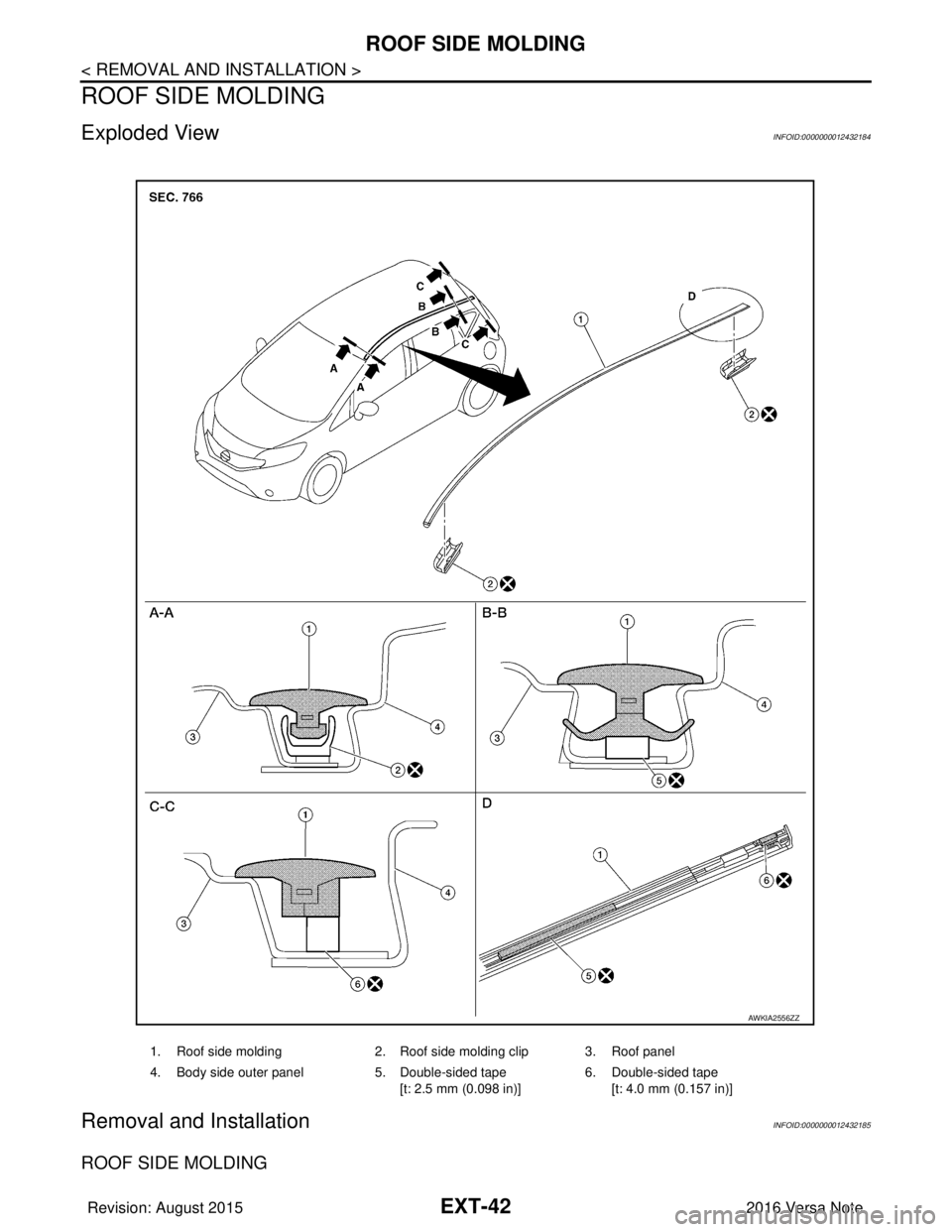
Exploded ViewINFOID:0000000012432184
Removal and InstallationINFOID:0000000012432185
ROOF SIDE MOLDING
1. Roof side molding2. Roof side molding clip 3. Roof panel
4. Body side outer panel 5. Double-sided tape
[t: 2.5 mm (0.098 in)] 6. Double-sided tape
[t: 4.0 mm (0.157 in)]
AWKIA2556ZZ
Revision: August 2015 2016 Versa Note
cardiagn.com
Page 1810 of 3641
ROOF SIDE MOLDINGEXT-43
< REMOVAL AND INSTALLATION >
C
DE
F
G H
I
J
L
M A
B
EXT
N
O P
Removal
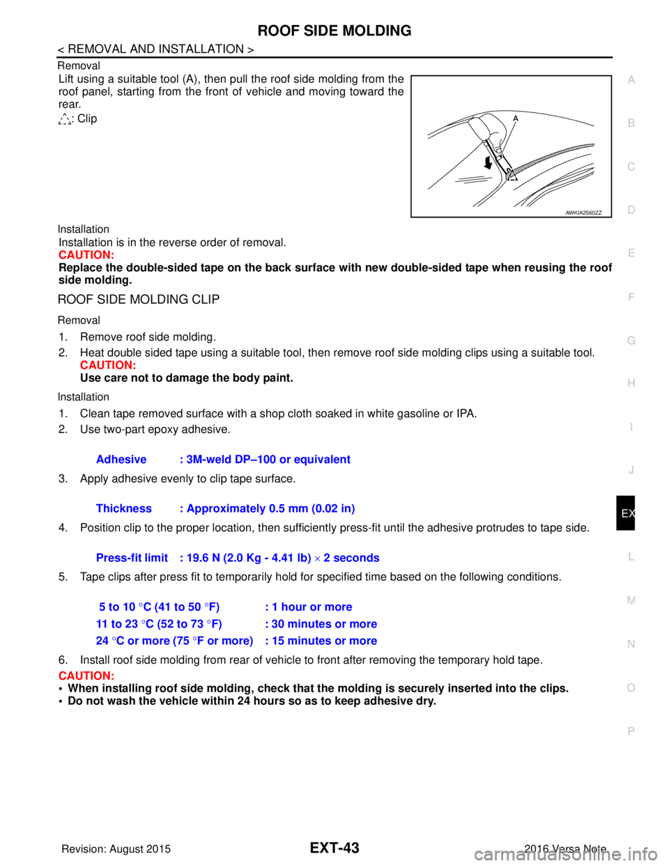
Lift using a suitable tool (A), then pull the roof side molding from the
roof panel, starting from the front of vehicle and moving toward the
rear.
: Clip
Installation
Installation is in the reverse order of removal.
CAUTION:
Replace the double-sided tape on the back surface with new double-sided tape when reusing the roof
side molding.
ROOF SIDE MOLDING CLIP
Removal
1. Remove roof side molding.
2. Heat double sided tape using a suitable tool, then remove roof side molding clips using a suitable tool.
CAUTION:
Use care not to damage the body paint.
Installation
1. Clean tape removed surface with a shop cloth soaked in white gasoline or IPA.
2. Use two-part epoxy adhesive.
3. Apply adhesive evenly to clip tape surface.
4. Position clip to the proper location, then sufficient ly press-fit until the adhesive protrudes to tape side.
5. Tape clips after press fit to temporarily hold for specified time based on the following conditions.
6. Install roof side molding from rear of vehicle to front after removing the temporary hold tape.
CAUTION:
• When installing roof side moldin g, check that the molding is securely inserted into the clips.
• Do not wash the vehicle within 24 hours so as to keep adhesive dry.
AWKIA2560ZZ
Adhesive : 3M-weld DP–100 or equivalent
Thickness : Approximately 0.5 mm (0.02 in)
Press-fit limit : 19.6 N (2.0 Kg - 4.41 lb) × 2 seconds
5 to 10 °C (41 to 50 °F) : 1 hour or more
11 to 23 °C (52 to 73 °F) : 30 minutes or more
24 °C or more (75 °F or more) : 15 minutes or more
Revision: August 2015 2016 Versa Note
cardiagn.com
Page 1868 of 3641
FL-2
< PRECAUTION >
PRECAUTIONS
PRECAUTION
PRECAUTIONS
Precaution for Supplemental Restraint System (SRS) "AIR BAG" and "SEAT BELT
PRE-TENSIONER"
INFOID:0000000012432103
The Supplemental Restraint System such as “A IR BAG” and “SEAT BELT PRE-TENSIONER”, used along
with a front seat belt, helps to reduce the risk or severity of injury to the driver and front passenger for certain
types of collision. Information necessary to service the system safely is included in the SR and SB section of
this Service Manual.
WARNING:
• To avoid rendering the SRS inopera tive, which could increase the risk of personal injury or death in
the event of a collision which would result in air bag inflation, all maintenance must be performed by
an authorized NISSAN/INFINITI dealer.
• Improper maintenance, including in correct removal and installation of the SRS, can lead to personal
injury caused by unintent ional activation of the system. For re moval of Spiral Cable and Air Bag
Module, see the SR section.
• Do not use electrical test equipmen t on any circuit related to the SRS unless instructed to in this
Service Manual. SRS wiring harn esses can be identified by yellow and/or orange harnesses or har-
ness connectors.
PRECAUTIONS WHEN USING POWER TOOLS (AIR OR ELECTRIC) AND HAMMERS
WARNING:
• When working near the Airbag Diagnosis Sensor Unit or other Airbag System sensors with the Igni-
tion ON or engine running, DO NOT use air or electri c power tools or strike near the sensor(s) with a
hammer. Heavy vibration could activate the sensor( s) and deploy the air bag(s), possibly causing
serious injury.
• When using air or electric power tools or hammers , always switch the Ignition OFF, disconnect the
battery and wait at least three minutes before performing any service.
General PrecautionINFOID:0000000012432104
WARNING:
When replacing fuel line parts, be sure to observe the following.
• Put a “CAUTION: FLAMMABLE” sign in the work area.
• Be sure to work in a well ventilated area and have a CO
2 fire extinguisher.
• Do not smoke while working on the fuel system. Keep open flames and sparks away from the work
area.
CAUTION:
• Before removing fuel line parts, carry out the following procedures:
- Put drained fuel in an explosi on-proof container and put the lid on securely. Keep the container in
safe area.
- Release fuel pressure from the fuel lines. Refer to EC-1
37, "Work Procedure" .
- Disconnect the battery ground
cable.
• Always replace O-rings and clamps with new ones.
• Do not kink or twist tubes when they are being installed.
• Do not tighten hose clamps excessi vely to avoid damaging hoses.
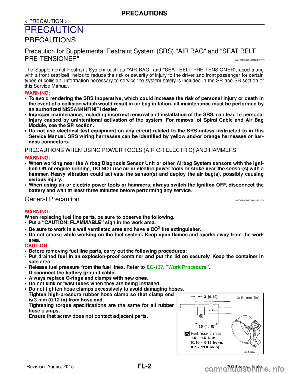
Tighten high-pressure rubber hose clamp so that clamp end
is 3 mm (0.12 in) from hose end.
Tightening torque specificati ons are the same for all rubber
hose clamps.
Ensure that screw does not contact adjacent parts.
MMA104A
Revision: August 2015 2016 Versa Note
cardiagn.com
Page 1928 of 3641
GI-40
< BASIC INSPECTION >
SERVICE INFORMATION FOR ELECTRICAL INCIDENT
• Connector damage and an intermittent connection can result from improperly probing of the connector dur-ing circuit checks.
• The probe of a digital multimeter (DMM) may not correctly fit the connector cavity. To correctly probe the
connector, follow the procedures below using a “T” pin. For the best contact grasp the “T” pin using an alliga-
tor clip.
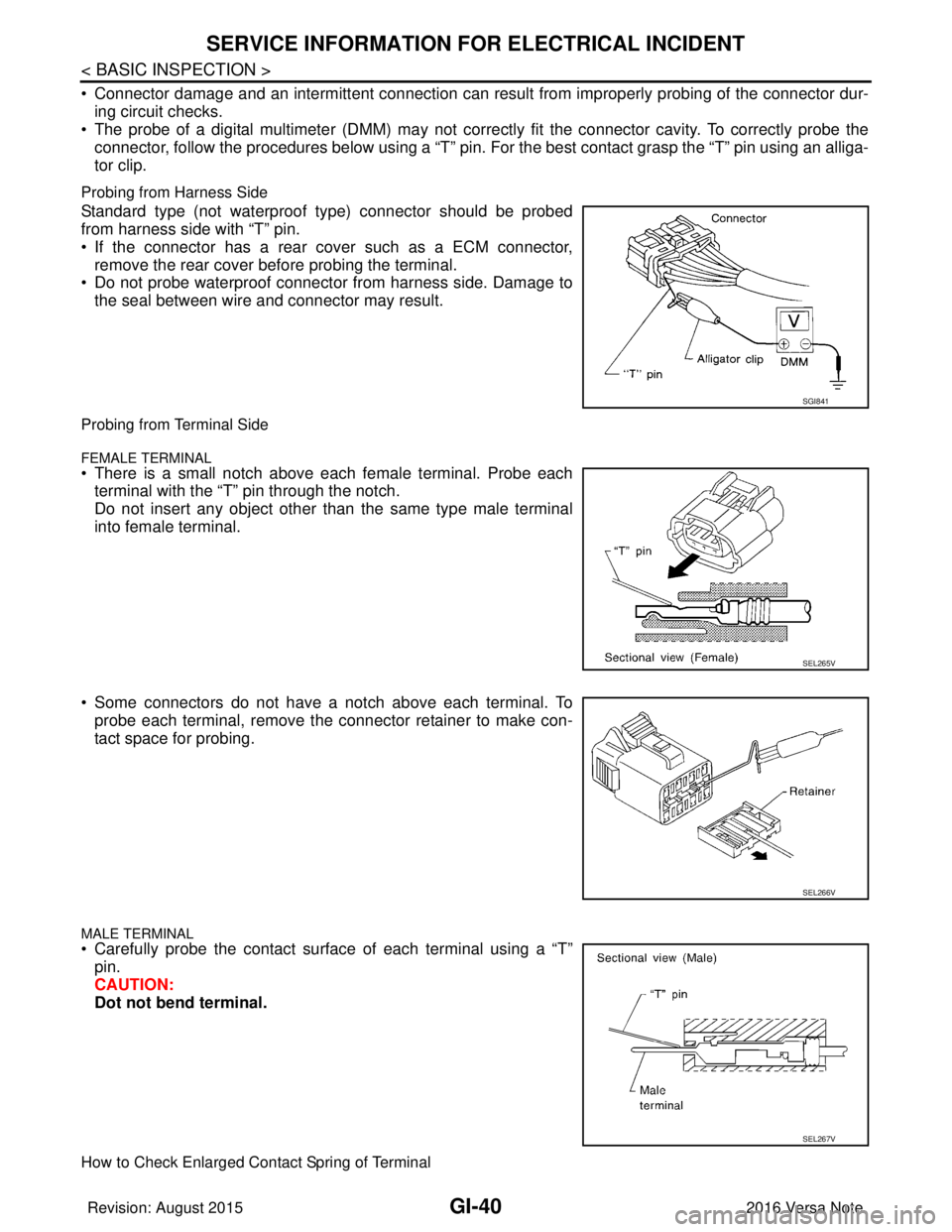
Probing from Harness Side
Standard type (not waterproof type) connector should be probed
from harness side with “T” pin.
• If the connector has a rear cover such as a ECM connector,remove the rear cover before probing the terminal.
• Do not probe waterproof connector from harness side. Damage to
the seal between wire and connector may result.
Probing from Terminal Side
FEMALE TERMINAL• There is a small notch above each female terminal. Probe eachterminal with the “T” pin through the notch.
Do not insert any object other than the same type male terminal
into female terminal.
• Some connectors do not have a notch above each terminal. To probe each terminal, remove the connector retainer to make con-
tact space for probing.
MALE TERMINAL
• Carefully probe the contact surface of each terminal using a “T”pin.
CAUTION:
Dot not bend terminal.
How to Check Enlarged Contact Spring of Terminal
SGI841
SEL265V
SEL266V
SEL267V
Revision: August 2015 2016 Versa Note
cardiagn.com
Page 1929 of 3641
SERVICE INFORMATION FOR ELECTRICAL INCIDENTGI-41
< BASIC INSPECTION >
C
DE
F
G H
I
J
K L
M B
GI
N
O P
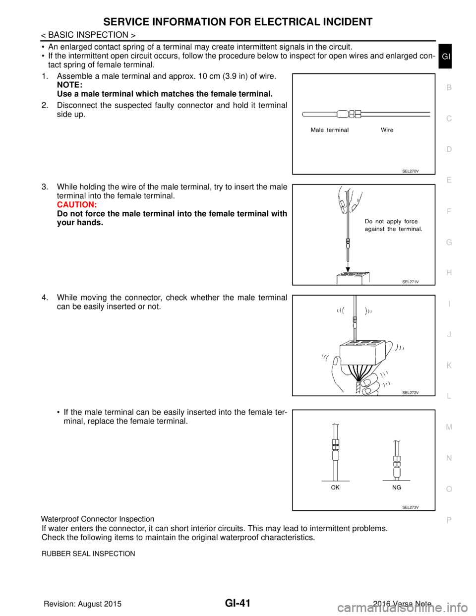
• An enlarged contact spring of a terminal may create intermittent signals in the circuit.
• If the intermittent open circuit occurs, follow the pr ocedure below to inspect for open wires and enlarged con-
tact spring of female terminal.
1. Assemble a male terminal and approx. 10 cm (3.9 in) of wire. NOTE:
Use a male terminal which matches the female terminal.
2. Disconnect the suspected faulty connector and hold it terminal side up.
3. While holding the wire of the male terminal, try to insert the male terminal into the female terminal.
CAUTION:
Do not force the male terminal into the female terminal with
your hands.
4. While moving the connector, check whether the male terminal can be easily inserted or not.
• If the male terminal can be easily inserted into the female ter-minal, replace the female terminal.
Waterproof Connector Inspection
If water enters the connector, it can short interior circuits. This may lead to intermittent problems.
Check the following items to maintain the original waterproof characteristics.
RUBBER SEAL INSPECTION
SEL270V
SEL271V
SEL272V
SEL273V
Revision: August 2015 2016 Versa Note
cardiagn.com