NISSAN NOTE 2016 Service Repair Manual
Manufacturer: NISSAN, Model Year: 2016, Model line: NOTE, Model: NISSAN NOTE 2016Pages: 3641, PDF Size: 28.72 MB
Page 3051 of 3641

SRC-34
< WIRING DIAGRAM >
SRS AIR BAG SYSTEM
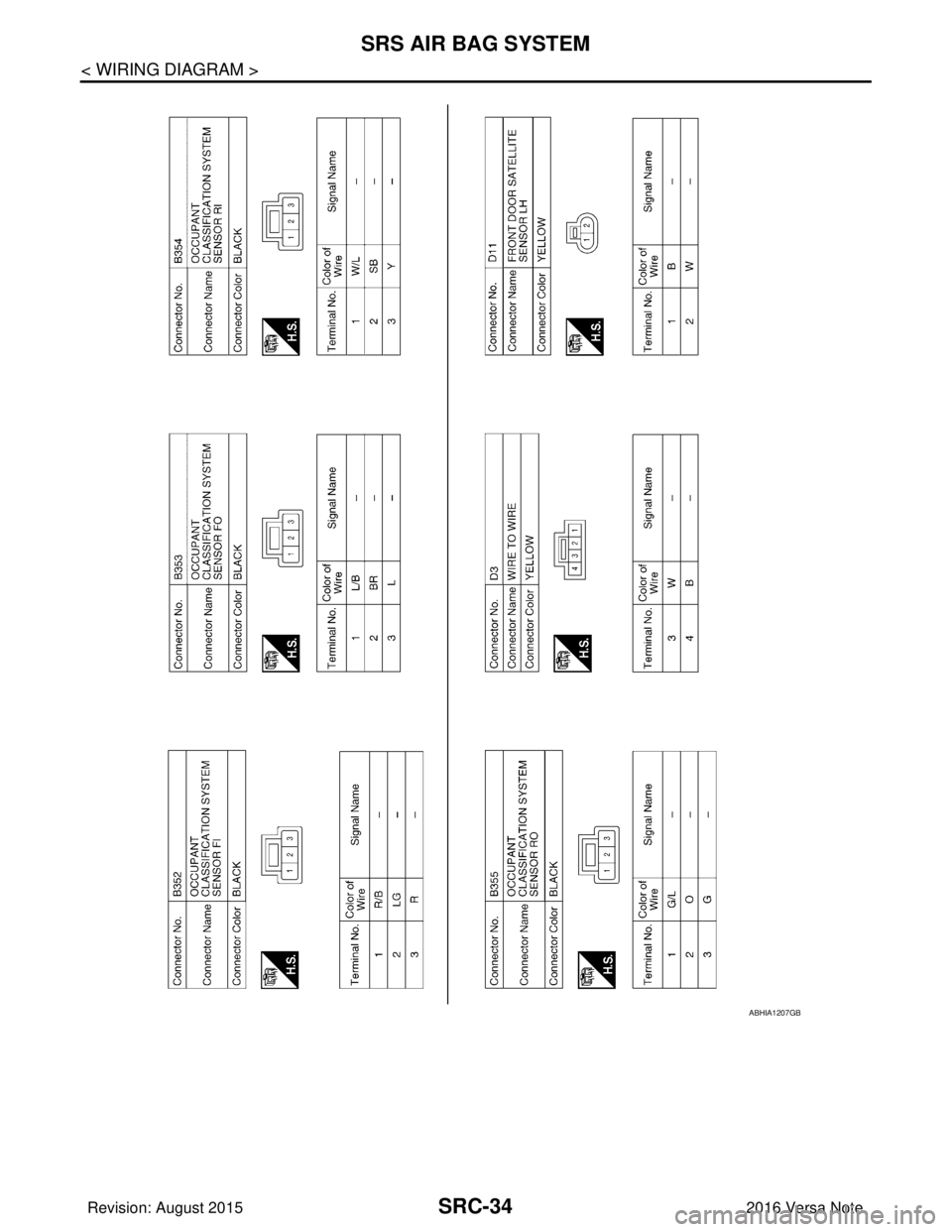
ABHIA1207GB
Revision: August 20152016 Versa Note
cardiagn.com
Page 3052 of 3641

SRS AIR BAG SYSTEMSRC-35
< WIRING DIAGRAM >
C
DE
F
G
I
J
K L
M A
B
SRC
N
O P
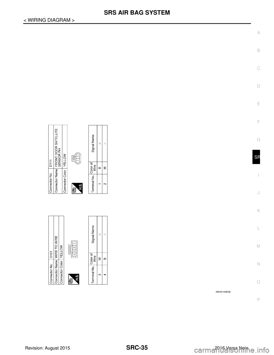
ABHIA1208GB
Revision: August 2015 2016 Versa Note
cardiagn.com
Page 3053 of 3641

SRC-36
< BASIC INSPECTION >
DIAGNOSIS AND REPAIR WORK FLOW
BASIC INSPECTION
DIAGNOSIS AND REPAIR WORK FLOW
Work FlowINFOID:0000000012430611
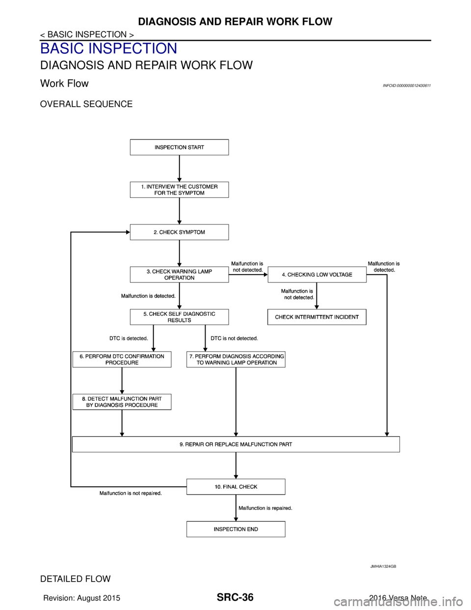
OVERALL SEQUENCE
DETAILED FLOW
JMHIA1324GB
Revision: August 20152016 Versa Note
cardiagn.com
Page 3054 of 3641

DIAGNOSIS AND REPAIR WORK FLOWSRC-37
< BASIC INSPECTION >
C
DE
F
G
I
J
K L
M A
B
SRC
N
O P
1.INTERVIEW THE CUSTOMER FOR THE SYMPTOM
Interview the customer for the symptom (the condi tion and the environment when the incident/malfunction
occurs).
>> GO TO 2.
2.CHECK SYMPTOM
Check the symptom from the customer information.
>> GO TO 3.
3.CHECK WARNING LAMP OPERATION
Check air bag warning lamp operation in the user mode.
Are any malfunction detected?
YES >> GO TO 5.
NO >> GO TO 4.
4.CHECK LOW VOLTAGE
Check low voltage with CONSULT.
Are any malfunction detected?
YES >> GO TO 9.
NO >> Check intermittent incident. Refer to GI-42, "
Intermittent Incident".
5.CHECK SELF DIAGNOSTIC RESULTS
Check self diagnostic result with CONSULT or diagnosis mode.
If it is impossible to switch to diagnosis mode, follow the same procedure that DTC is not detected.
NOTE:
Perform the following procedure if DTC is detected.
• Record DTC (Print them out with CONSULT.)
• Erase self diagnostic result.
• Study the relationship between the malfunction that DTC or air bag warning lamp indicates and the symptom that the customer describes.
• Check related service bulletins for information.
Is DTC detected?
YES >> GO TO 6.
NO >> GO TO 7.
6.PERFORM DTC CONFIRMATION PROCEDURE
Perform DTC CONFIRMATION PROCEDURE for the DTC.
>> GO TO 8.
7.PERFORM DIAGNOSIS ACCORDING TO WARNING LAMP OPERATION
1. Check air bag warning lamp operation in the user mode.
2. Perform Diagnosis Procedure for the air bag warning lamp operation.
>> GO TO 9.
8.DETECT MALFUNCTIONING PA RT BY DIAGNOSTIC PROCEDURE
Inspect according to Diagnostic Procedure of the DTC.
>> GO TO 9.
9.REPAIR OR REPLACE THE MALFUNCTION PART
Repair or replace the malfunctioning part.
Revision: August 2015 2016 Versa Note
cardiagn.com
Page 3055 of 3641

SRC-38
< BASIC INSPECTION >
DIAGNOSIS AND REPAIR WORK FLOW
>> GO TO 10.
10.ON BOARD DIAGNOSIS FUNCTION
Check self diagnostic result and air bag warning lamp operation in the user mode.
Is the malfunction repaired?
YES >> Inspection End.
NO >> GO TO 2.
Revision: August 2015 2016 Versa Note
cardiagn.com
Page 3056 of 3641

INSPECTION AND ADJUSTMENTSRC-39
< BASIC INSPECTION >
C
DE
F
G
I
J
K L
M A
B
SRC
N
O P
INSPECTION AND ADJUSTMENT
ADDITIONAL SERVICE WHEN REPLACING CONTROL UNIT
ADDITIONAL SERVICE WHEN REPL ACING CONTROL UNIT : Description
INFOID:0000000012430612
Always perform zero point reset using CONSULT when removing and installing the passenger seat or servic-
ing the occupant classification system. If zero point reset is not performed the OCS may not operate normally,
which may increase the risk of serious injury in a collision.
ADDITIONAL SERVICE WHEN REPLACING CONTROL UNIT : Special Repair Re-
quirement
INFOID:0000000012430613
WORK PROCEDURE WHEN REPLACING CONTROL UNIT
1.PERFORM ZERO POINT RESET
Perform zero point reset. Refer to SRC-39, "
ZERO POINT RESET : Special Repair Requirement".
Is zero point reset performed normally?
YES >> INSPECTION END
NO >> Check condition as per the following, and perform zero point reset again. • Passenger seat is occupied by an object.
• Excessive vibration is applied while performing zero point reset.
• Occupant detection system is malfunctioning.NOTE:
If “Incomplete” is displayed on “zero point reset cu rrent status”, zero point reset is not completed
normally. Check the condition as per the following and perform zero point reset again.
• Passenger seat is occupied by an object.
• Excessive vibration is applied while performing zero point reset.
• Occupant detection system is malfunctioning.
ZERO POINT RESET
ZERO POINT RESET : DescriptionINFOID:0000000012430614
Zero point reset is an initializing procedure for occupant detection sensor that must be performed when replac-
ing or removing and installing passenger seat.
If zero point reset is not performed, the initializati on is incomplete and Occupant Detection System does not
operate normally.
NOTE:
• When zero point reset is performed once after removal and installation of passenger seat, CONSULT dis- plays “complete”.
• When reinstalling passenger seat after removal, the initial value for occupant detection sensor changes, and
Occupant Detection System does not operate normally.
• Always perform zero point reset after performing the work as per the following.
- Reinstallation of passenger seat
- Installation of passenger seat that is zero point reset complete
- Installation of passenger seat that is zero point reset in complete
ZERO POINT RESET : Special Repair RequirementINFOID:0000000012430615
1.PERFORM ZERO POINT RESET
1. Perform zero point reset. NOTE:
When performing zero point reset, be careful of the items described as per the following.
• Perform zero point reset after installing passenger seat to the vehicle
• Do not put any objects on passenger seat
• Do not apply excessive vibration to the vehicle
• Do not touch the vehicle
• Do not tilt the vehicle
Revision: August 2015 2016 Versa Note
cardiagn.com
Page 3057 of 3641

SRC-40
< BASIC INSPECTION >
INSPECTION AND ADJUSTMENT
2. Select start on “Zero point reset function” screen from, WORK SUPPORT of CONSULT “OCCUPANT
DETECTION”.
3. “Zero point reset” starts.
>> GO TO 2.
2.CONFIRMATION OF SETTING
1. Proceed to “Zero point reset function” screen from work support of CONSULT “OCCUPANT DETEC-
TION”.
2. Check that “Complete” or “Incomplete” is displayed on “Zero point reset status”.
CAUTION:
• “Complete” is displayed on “zero point reset current status” if the seat is reinstalled by seat removal
and installation, or “zero point reset” is already performed.
• “Zero point reset current status” displays “Incompl ete” if a new seat is installed. When turning key
switch ON without performing zero point reset , front passenger air bag OFF indicator turns ON.
When zero point reset is performed, front passenger air bag OFF indicator turns OFF.
• Air bag warning lamp blinks in user mode only.
• Air bag sensor unit does not record whethe r or not zero point reset is performed.
Is condition
“ALREADY PERFORMED”?
YES >> Print out “ZERO POINT RESET CURRENT STATUS” screen, and inspection end.
NO >> Check condition as per the following, and perform zero point reset again. • Passenger seat is occupied by an object.
• Excessive vibration is applied while performing zero point reset.
• Occupant detection system is malfunctioning.NOTE:
If “Incomplete” is displayed on “zero point reset cu rrent status”, zero point reset is not completed
normally. Check the condition as per the following and perform zero point reset again.
• Passenger seat is occupied by an object.
• Excessive vibration is applied while performing zero point reset.
• Occupant detection system is malfunctioning.
Revision: August 2015 2016 Versa Note
cardiagn.com
Page 3058 of 3641

INTERMITTENT INCIDENTSRC-41
< BASIC INSPECTION >
C
DE
F
G
I
J
K L
M A
B
SRC
N
O P
INTERMITTENT INCIDENT
Inspection ProcedureINFOID:0000000012430616
INTERMITTENT TROUBLE
An intermittent incident may have occurred in the past but is not being detected currently. This DTC will not be
detected on SELF-DIAG [CURRENT], but may be view ed on SELF-DIAG [PAST] if the DTC has not been
erased. Refer to SRC-16, "
Trouble Diagnosis with CONSULT".
Revision: August 2015 2016 Versa Note
cardiagn.com
Page 3059 of 3641

SRC-42
< DTC/CIRCUIT DIAGNOSIS >
B0001, B0002 DRIVER AIRBAG MODULE
DTC/CIRCUIT DIAGNOSIS
B0001, B0002 DRIVER AIRBAG MODULE
DTC LogicINFOID:0000000012430617
DTC DETECTION LOGIC
DTC CONFIRMATION PROCEDURE (With CONSULT)
1.CHECK SELF-DIAG RESULT
1. Turn ignition switch ON.
2. Check for DTC using CONSULT.
Is the DTC detected?
YES (Current DTC)>>Refer to SRC-43, "Diagnosis Procedure".
YES (Past DTC)>>GO TO 2.
NO >> Inspection End.
2.ERASE SELF-DIAG RESULT
Erase the DTC using CONSULT.
Can the DTC be erased?
YES >> Inspection End.
NO >> Refer to SRC-43, "
Diagnosis Procedure".
DTC CONFIRMATION PROCEDURE (Without CONSULT)
1.CHECK SELF-DIAG RESULT
1. Turn ignition switch ON.
2. Check the air bag warning lamp status. Refer to SRC-14, "
On Board Diagnosis Function".
NOTE:
SRS will not enter diagnosis mode if no malfunction is detected in user mode.
CONSULT nameDTC DTC detecting condition Repair order
DRIVER AIRBAG MODULE CIRCUIT [OPEN]
B0001Driver air bag module circuit
(DR1) is open
(including the spiral cable).
Refer to
SRC-43, "
Diagnosis Proce-
dure".
DRIVER AIRBAG MODULE CIRCUIT [VB-SHORT] Driver air bag module circuit
(DR1) is shorted to a power sup-
ply circuit
(including the spiral cable).
DRIVER AIRBAG MODULE CIRCUIT [GND-SHORT] Driver air bag module circuit
(DR1) is shorted to ground
(including the spiral cable).
DRIVER AIRBAG MODULE CIRCUIT [SHORT] Driver air bag module circuits
(DR1) are shorted to each other
(including the spiral cable).
DRIVER AIRBAG MODULE 2ND CIRCUIT [OPEN]
B0002Driver air bag module circuit
(DR2) is open
(including the spiral cable).
DRIVER AIRBAG MODULE 2ND CIRCUIT [VB-SHORT] Driver air bag module circuit
(DR2) is shorted to a power sup-
ply circuit
(including the spiral cable).
DRIVER AIRBAG MODULE 2ND CIRCUIT [GND-SHORT] Driver air bag module circuit
(DR2) is shorted to ground
(including the spiral cable).
DRIVER AIRBAG MODULE 2ND CIRCUIT [SHORT] Driver air bag module circuits
(DR2) are shorted to each other
(including the spiral cable).
Revision: August 2015
2016 Versa Note
cardiagn.com
Page 3060 of 3641

B0001, B0002 DRIVER AIRBAG MODULE
SRC-43
< DTC/CIRCUIT DIAGNOSIS >
C
D E
F
G
I
J
K L
M A
B
SRC
N
O P
Is the DTC detected?
YES >> Refer to SRC-43, "Diagnosis Procedure".
NO >> Inspection End.
Diagnosis ProcedureINFOID:0000000012430618
WARNING:
• Before servicing, turn ignition sw itch OFF, disconnect battery negative terminal, and wait 3 minutes
or more. (To discharge backup capacitor.)
• Never use unspecified tester or other measuring device.
1.HARNESS CONNECTOR
Visually inspect all applicable harness connectors for the following:
• Visible damage to connector or terminal
• Loose terminal
• Poor connection NOTE:
All harness connectors should be inspected from t he air bag diagnosis sensor unit to the end component
(including any in-line connectors).
Is the inspection result normal?
YES >> GO TO 2.
NO >> Perform one of the following repairs: • Visible damage: Replace the harness.
• Loose terminal: Secure the terminal.
• Poor connection: Secure the connection.
2.CONFIRM DTC
1. Reconnect all harness connectors.
2. Turn ignition switch ON.
3. Check for DTC using CONSULT.
Is DTC still current?
YES >> GO TO 3.
NO >> Refer to GI-42, "
Intermittent Incident".
3.WIRING HARNESS
Check the wiring harness for visible damage.
NOTE:
The entire wiring harness should be inspected from the air bag diagnosis sensor unit to the end component
(including any in-line connectors).
Is the inspection result normal?
YES >> GO TO 4.
NO >> Replace the harness.
4.CHECK SPIRAL CABLE CIRCUIT
1. Turn ignition switch OFF.
2. Disconnect driver air bag module harness connector and combination switch (spiral cable) harness con- nector.
3. Check continuity between driver air bag module har ness connector and combination switch (spiral cable)
harness connector.
4. Check continuity between driver air bag module harness connector and ground.
Driver air bag module Combination switch (spiral cable)
Continuity
Connector TerminalConnector Terminal
M86 9
M30 30
Ye s
12
29
M87 10
28
11 3 0
Revision: August 2015 2016 Versa Note
cardiagn.com