NISSAN NOTE 2016 Service Repair Manual
Manufacturer: NISSAN, Model Year: 2016, Model line: NOTE, Model: NISSAN NOTE 2016Pages: 3641, PDF Size: 28.72 MB
Page 3021 of 3641

SRC-4
< PRECAUTION >
PRECAUTIONS
PRECAUTION
PRECAUTIONS
Precaution for Supplemental Restraint System (SRS) "AIR BAG" and "SEAT BELT
PRE-TENSIONER"
INFOID:0000000012430587
The Supplemental Restraint System such as “A IR BAG” and “SEAT BELT PRE-TENSIONER”, used along
with a front seat belt, helps to reduce the risk or severity of injury to the driver and front passenger for certain
types of collision. Information necessary to service the system safely is included in the SR and SB section of
this Service Manual.
WARNING:
• To avoid rendering the SRS inopera tive, which could increase the risk of personal injury or death in
the event of a collision which would result in air bag inflation, all maintenance must be performed by
an authorized NISSAN/INFINITI dealer.
• Improper maintenance, including in correct removal and installation of the SRS, can lead to personal
injury caused by unintent ional activation of the system. For re moval of Spiral Cable and Air Bag
Module, see the SR section.
• Do not use electrical test equipmen t on any circuit related to the SRS unless instructed to in this
Service Manual. SRS wiring harn esses can be identified by yellow and/or orange harnesses or har-
ness connectors.
PRECAUTIONS WHEN USING POWER TOOLS (AIR OR ELECTRIC) AND HAMMERS
WARNING:
• When working near the Airbag Diagnosis Sensor Unit or other Airbag System sensors with the Igni-
tion ON or engine running, DO NOT use air or electri c power tools or strike near the sensor(s) with a
hammer. Heavy vibration could activate the sensor( s) and deploy the air bag(s), possibly causing
serious injury.
• When using air or electric power tools or hammers , always switch the Ignition OFF, disconnect the
battery and wait at least three minutes before performing any service.
ServiceINFOID:0000000012430588
• Never use electrical test equipment to check SRS circuits unless instructed to in this Service Manual.
• Before servicing the SRS, turn ignition switch OF F, disconnect battery negative terminal and wait 3 minutes
or more.
For approximately 3 minutes after the cables are removed, it is still possible for the air bag and seat belt pre-
tensioner to deploy. Therefore, never work on any SR S connectors or wires until at least 3 minutes have
passed.
• Diagnosis sensor unit must always be installed with their arrow marks “ ⇐” pointing towards the front of the
vehicle for proper operation. Also chec k diagnosis sensor unit for cracks, deformities or rust before installa-
tion and replace as required.
• The spiral cable must be aligned with the neutral position since its rotations are limited. Never turn steering wheel and column after removal of steering gear.
• Handle air bag module carefully. Always place driver and front passenger air bag modules with the pad side facing upward and seat mounted front side air bag module standing with the stud bolt side facing down.
• Conduct self-diagnosis to check entire SRS for proper function after replacing any components.
• After air bag inflates, the front instrument panel assembly should be replaced if damaged.
• Always replace instrument panel pad following front passenger air bag deployment.
• Never solder the harness when making repairs. Check that harness is not pinched and that there is no con-
tact with other components.
• Never allow harness to come in contact with oil, grease, waste oil, or water.
• Never insert foreign materials, such as a screwdriver, into the harness connector. (This is to prevent acci- dental activation caused by static electricity.)
• Always use CONSULT or SRS air bag warning lamp to perform the circuit diagnosis. (Never use an electric tester such as a circuit tester.)
Revision: August 2015 2016 Versa Note
cardiagn.com
Page 3022 of 3641
COMPONENT PARTSSRC-5
< SYSTEM DESCRIPTION >
C
DE
F
G
I
J
K L
M A
B
SRC
N
O P
SYSTEM DESCRIPTION
COMPONENT PARTS
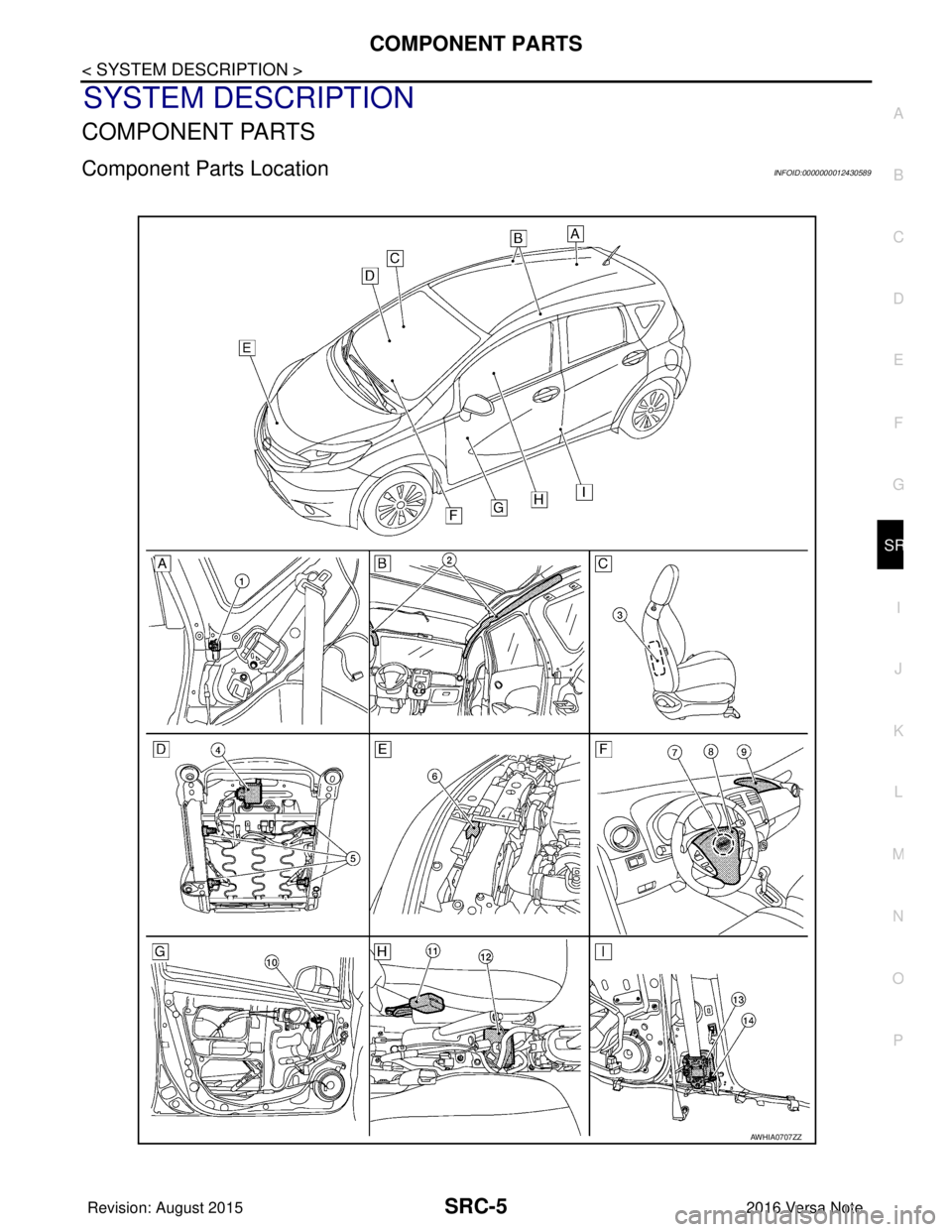
Component Parts LocationINFOID:0000000012430589
AWHIA0707ZZ
Revision: August 2015 2016 Versa Note
cardiagn.com
Page 3023 of 3641
SRC-6
< SYSTEM DESCRIPTION >
COMPONENT PARTS
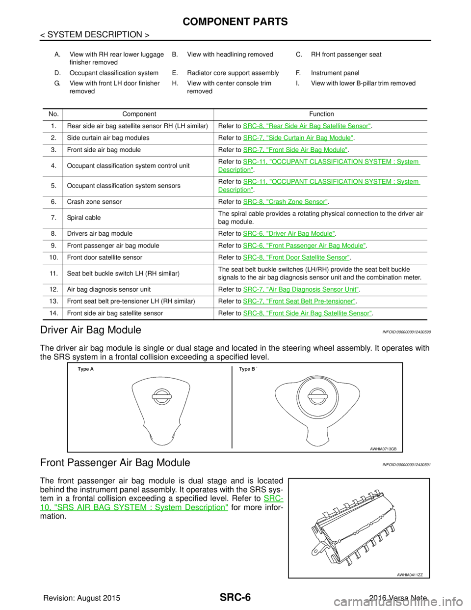
Driver Air Bag Module
INFOID:0000000012430590
The driver air bag module is single or dual stage and located in the steering wheel assembly. It operates with
the SRS system in a frontal collision exceeding a specified level.
Front Passenger Air Bag ModuleINFOID:0000000012430591
The front passenger air bag module is dual stage and is located
behind the instrument panel assembly. It operates with the SRS sys-
tem in a frontal collision exceeding a specified level. Refer to SRC-
10, "SRS AIR BAG SYSTEM : System Description" for more infor-
mation.
A. View with RH rear lower luggage
finisher removed B. View with headlining removed C. RH front passenger seat
D. Occupant classification system E. Radiator core support assembly F. Instrument panel
G. View with front LH door finisher removed H. View with center console trim
removed I. View with lower B-pillar trim removed
No. Component Function
1. Rear side air bag satellite sensor RH (LH similar) Refer to SRC-8, "
Rear Side Air Bag Satellite Sensor".
2. Side curtain air bag modules Refer to SRC-7, "
Side Curtain Air Bag Module".
3. Front side air bag module Refer to SRC-7, "
Front Side Air Bag Module".
4. Occupant classification system control unit Refer to SRC-11, "
OCCUPANT CLASSIFICATION SYSTEM : System
Description".
5. Occupant classification system sensors Refer to SRC-11, "
OCCUPANT CLASSIFICATION SYSTEM : System
Description".
6. Crash zone sensor Refer to SRC-8, "
Crash Zone Sensor".
7. Spiral cable The spiral cable provides a rotating physical connection to the driver air
bag module.
8. Drivers air bag module Refer to SRC-6, "
Driver Air Bag Module".
9. Front passenger air bag module Refer to SRC-6, "
Front Passenger Air Bag Module".
10. Front door satellite sensor Refer to SRC-8, "
Front Door Satellite Sensor".
11. Seat belt buckle switch LH (RH similar) The seat belt buckle switches (LH/RH) provide the seat belt buckle
signals to the air bag diagnosis sensor unit and the combination meter.
12. Air bag diagnosis sensor unit Refer to SRC-7, "
Air Bag Diagnosis Sensor Unit".
13. Front seat belt pre-tensioner LH (RH similar) Refer to SRC-7, "
Front Seat Belt Pre-tensioner".
14. Front side air bag satellite sensor Refer to SRC-8, "
Front Side Air Bag Satellite Sensor".
AWHIA0713GB
AWHIA0411ZZ
Revision: August 2015 2016 Versa Note
cardiagn.com
Page 3024 of 3641
COMPONENT PARTSSRC-7
< SYSTEM DESCRIPTION >
C
DE
F
G
I
J
K L
M A
B
SRC
N
O P
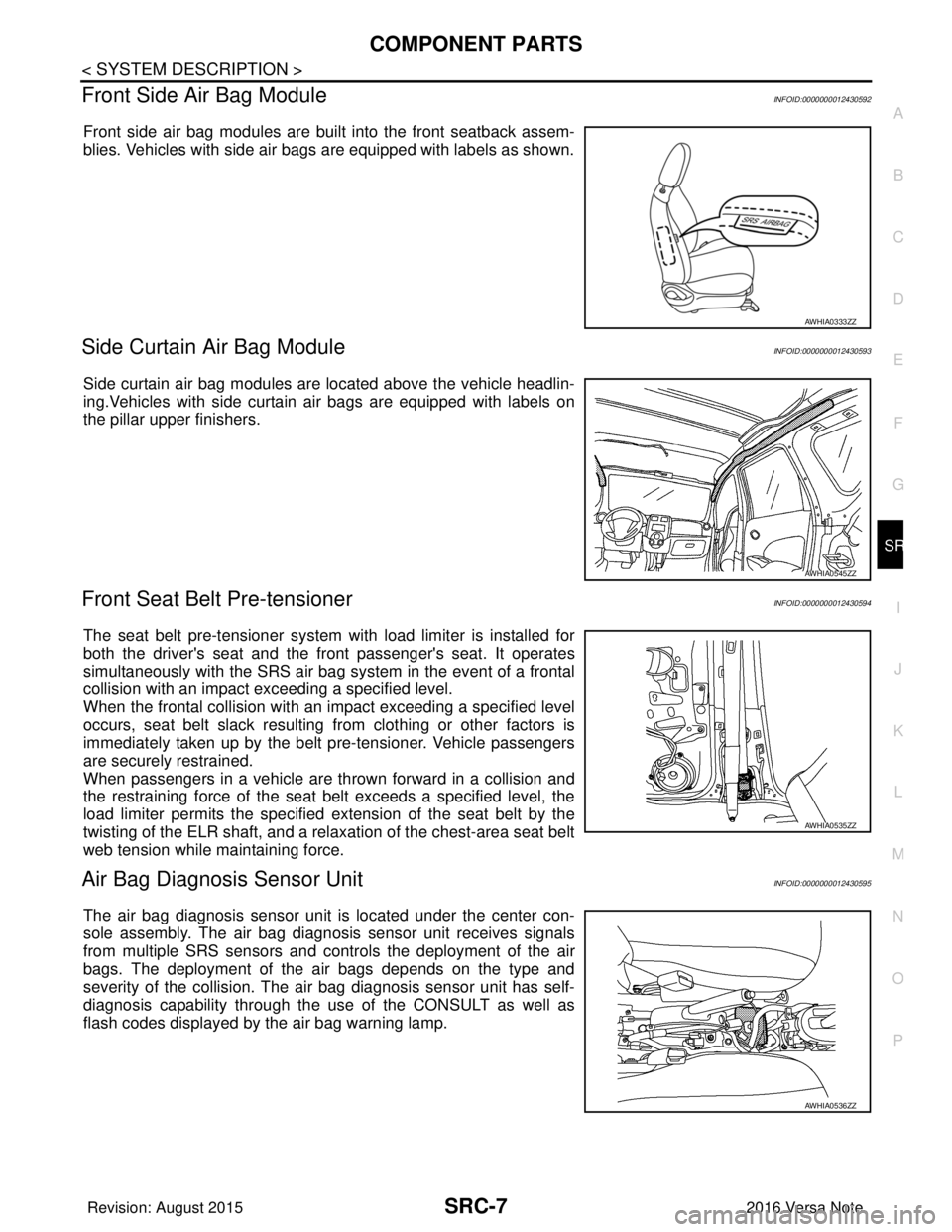
Front Side Air Bag ModuleINFOID:0000000012430592
Front side air bag modules are built into the front seatback assem-
blies. Vehicles with side air bags are equipped with labels as shown.
Side Curtain Air Bag ModuleINFOID:0000000012430593
Side curtain air bag modules are located above the vehicle headlin-
ing.Vehicles with side curtain air bags are equipped with labels on
the pillar upper finishers.
Front Seat Belt Pre-tensionerINFOID:0000000012430594
The seat belt pre-tensioner system with load limiter is installed for
both the driver's seat and the fr ont passenger's seat. It operates
simultaneously with the SRS air bag system in the event of a frontal
collision with an impact exceeding a specified level.
When the frontal collision with an im pact exceeding a specified level
occurs, seat belt slack resulting from clothing or other factors is
immediately taken up by the belt pre-tensioner. Vehicle passengers
are securely restrained.
When passengers in a vehicle are thrown forward in a collision and
the restraining force of the seat belt exceeds a specified level, the
load limiter permits the specified ex tension of the seat belt by the
twisting of the ELR shaft, and a relaxation of the chest-area seat belt
web tension while maintaining force.
Air Bag Diagnosis Sensor UnitINFOID:0000000012430595
The air bag diagnosis sensor unit is located under the center con-
sole assembly. The air bag diagnosis sensor unit receives signals
from multiple SRS sensors and cont rols the deployment of the air
bags. The deployment of the air bags depends on the type and
severity of the collision. The air bag diagnosis sensor unit has self-
diagnosis capability through the us e of the CONSULT as well as
flash codes displayed by the air bag warning lamp.
AWHIA0333ZZ
AWHIA0545ZZ
AWHIA0535ZZ
AWHIA0536ZZ
Revision: August 2015 2016 Versa Note
cardiagn.com
Page 3025 of 3641
SRC-8
< SYSTEM DESCRIPTION >
COMPONENT PARTS
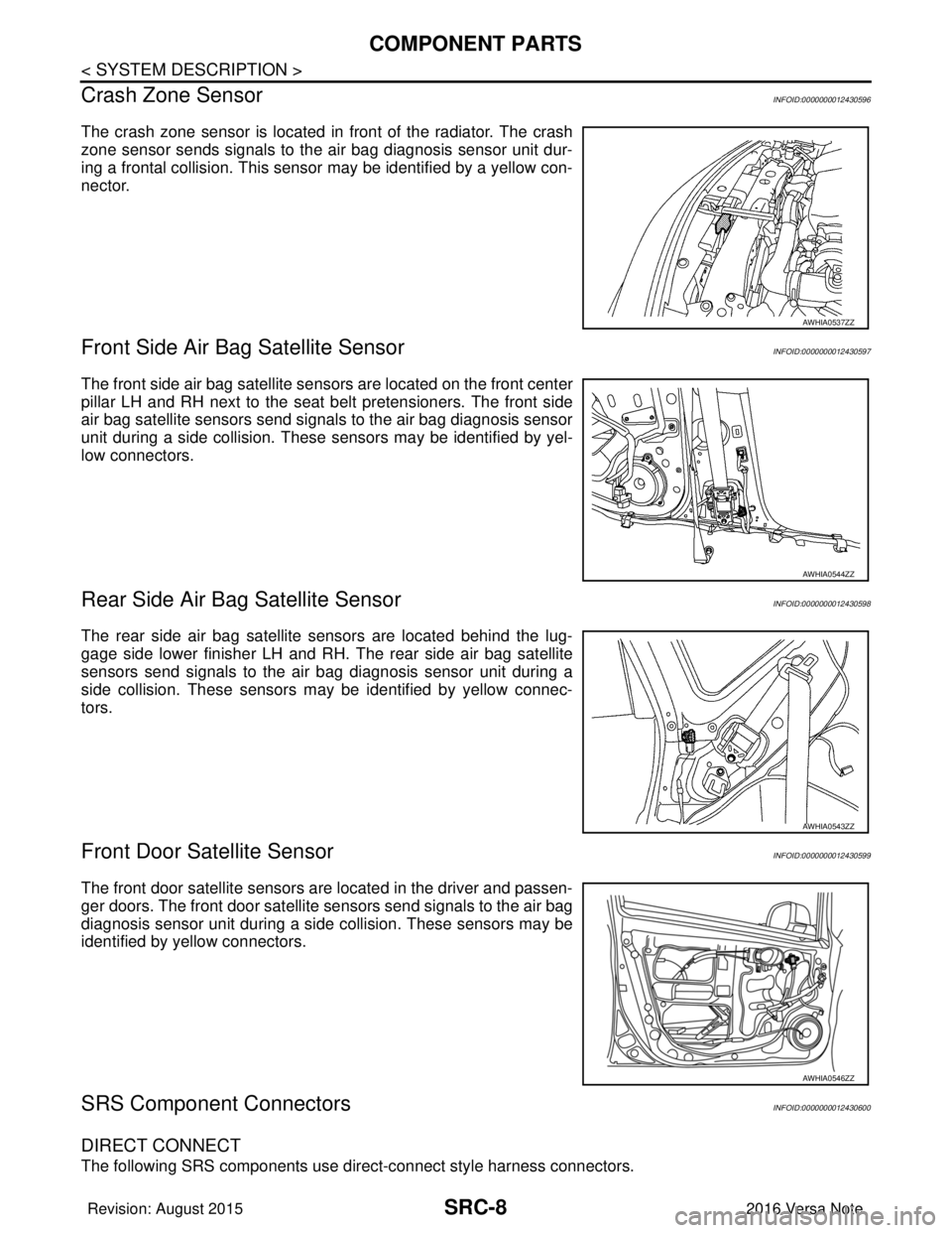
Crash Zone Sensor
INFOID:0000000012430596
The crash zone sensor is located in front of the radiator. The crash
zone sensor sends signals to the air bag diagnosis sensor unit dur-
ing a frontal collision. This sensor may be identified by a yellow con-
nector.
Front Side Air Bag Satellite SensorINFOID:0000000012430597
The front side air bag satellite sensors are located on the front center
pillar LH and RH next to the seat belt pretensioners. The front side
air bag satellite sensors send signals to the air bag diagnosis sensor
unit during a side collision. These sensors may be identified by yel-
low connectors.
Rear Side Air Bag Satellite SensorINFOID:0000000012430598
The rear side air bag satellite sensors are located behind the lug-
gage side lower finisher LH and RH. The rear side air bag satellite
sensors send signals to the air bag diagnosis sensor unit during a
side collision. These sensors may be identified by yellow connec-
tors.
Front Door Satellite SensorINFOID:0000000012430599
The front door satellite sensors are located in the driver and passen-
ger doors. The front door satellite sensors send signals to the air bag
diagnosis sensor unit during a side collision. These sensors may be
identified by yellow connectors.
SRS Component ConnectorsINFOID:0000000012430600
DIRECT CONNECT
The following SRS components use direct-connect style harness connectors.
AWHIA0537ZZ
AWHIA0544ZZ
AWHIA0543ZZ
AWHIA0546ZZ
Revision: August 2015 2016 Versa Note
cardiagn.com
Page 3026 of 3641
COMPONENT PARTSSRC-9
< SYSTEM DESCRIPTION >
C
DE
F
G
I
J
K L
M A
B
SRC
N
O P
• Driver front air bag module
• Passenger front air bag module
• LH side curtain air bag module
• RH side curtain air bag module
• Front LH seat belt pre-tensioner
• Front RH seat belt pre-tensioner
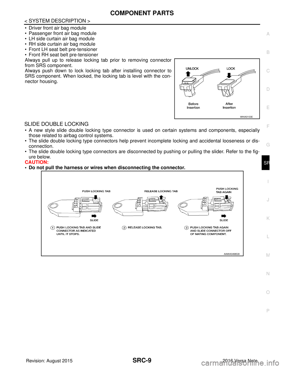
Always pull up to release locking tab prior to removing connector
from SRS component.
Always push down to lock locking tab after installing connector to
SRS component. When locked, the locking tab is level with the con-
nector housing.
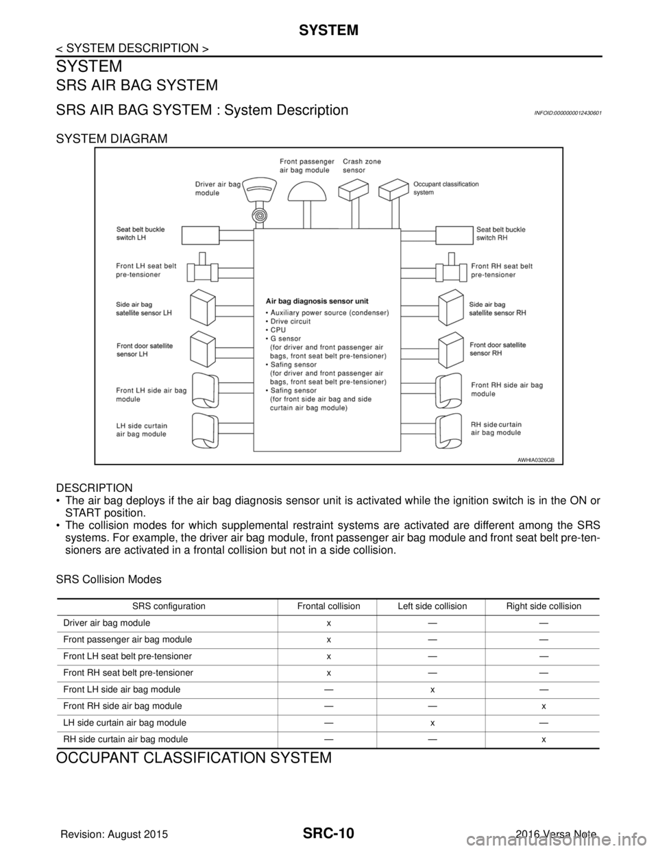
SLIDE DOUBLE LOCKING
• A new style slide double locking type connector is used on certain systems and components, especially those related to airbag control systems.
• The slide double locking type connectors help prevent incomplete locking and accidental looseness or dis-
connection.
• The slide double locking type connectors are disconnected by pushing or pulling the slider. Refer to the fig- ure below.
CAUTION:
• Do not pull the harness or wires when disconnecting the connector.
WHIA0103E
AAMIA0498GB
Revision: August 2015 2016 Versa Note
cardiagn.com
Page 3027 of 3641
SRC-10
< SYSTEM DESCRIPTION >
SYSTEM
SYSTEM
SRS AIR BAG SYSTEM
SRS AIR BAG SYSTEM : System DescriptionINFOID:0000000012430601
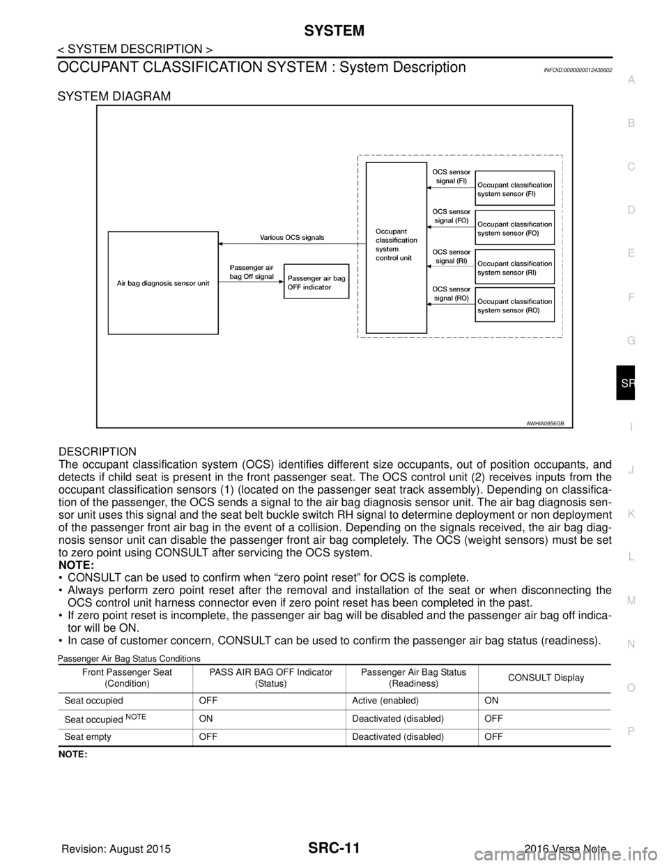
SYSTEM DIAGRAM
DESCRIPTION
• The air bag deploys if the air bag diagnosis sensor unit is activated while the ignition switch is in the ON orSTART position.
• The collision modes for which supplemental restraint systems are activated are different among the SRS
systems. For example, the driver air bag module, fr ont passenger air bag module and front seat belt pre-ten-
sioners are activated in a frontal collision but not in a side collision.
SRS Collision Modes
OCCUPANT CLASSIFICATION SYSTEM
AWHIA0326GB
SRS configuration Frontal collision Left side collision Right side collision
Driver air bag module x— —
Front passenger air bag module x— —
Front LH seat belt pre-tensioner x— —
Front RH seat belt pre-tensioner x— —
Front LH side air bag module —x —
Front RH side air bag module —— x
LH side curtain air bag module —x —
RH side curtain air bag module —— x
Revision: August 2015 2016 Versa Note
cardiagn.com
Page 3028 of 3641
SYSTEMSRC-11
< SYSTEM DESCRIPTION >
C
DE
F
G
I
J
K L
M A
B
SRC
N
O P
OCCUPANT CLASSIFICATION SYSTEM : System DescriptionINFOID:0000000012430602
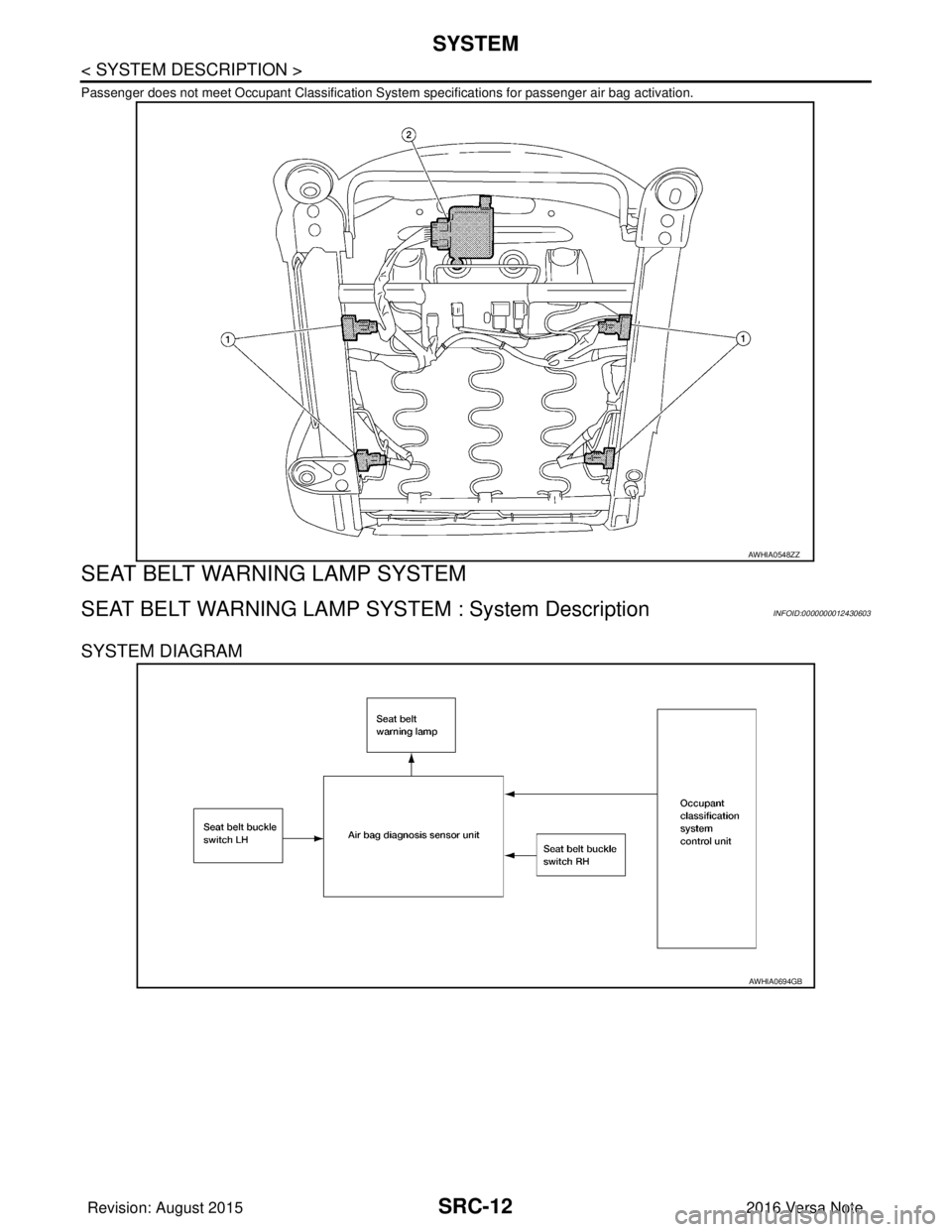
SYSTEM DIAGRAM
DESCRIPTION
The occupant classification system (OCS) identifies diff erent size occupants, out of position occupants, and
detects if child seat is present in the front passenger seat. The OCS control unit (2) receives inputs from the
occupant classification sensors (1) (located on the pa ssenger seat track assembly). Depending on classifica-
tion of the passenger, the OCS sends a signal to the air bag diagnosis sensor unit. The air bag diagnosis sen-
sor unit uses this signal and the seat belt buckle swit ch RH signal to determine deployment or non deployment
of the passenger front air bag in the event of a co llision. Depending on the signals received, the air bag diag-
nosis sensor unit can disable the passenger front air bag completely. The OCS (weight sensors) must be set
to zero point using CONSULT after servicing the OCS system.
NOTE:
• CONSULT can be used to confirm when “zero point reset” for OCS is complete.
• Always perform zero point reset after the removal and installation of the seat or when disconnecting the OCS control unit harness connector even if zero point reset has been completed in the past.
• If zero point reset is incomplete, the passenger air bag will be disabled and the passenger air bag off indica-
tor will be ON.
• In case of customer concern, CONSULT can be us ed to confirm the passenger air bag status (readiness).
Passenger Air Bag Status Conditions
NOTE:
AWHIA0656GB
Front Passenger Seat
(Condition) PASS AIR BAG OFF Indicator
(Status) Passenger Air Bag Status
(Readiness) CONSULT Display
Seat occupied OFF Active (enabled)ON
Seat occupied
NOTEON Deactivated (disabled) OFF
Seat empty OFF Deactivated (disabled) OFF
Revision: August 2015 2016 Versa Note
cardiagn.com
Page 3029 of 3641
SRC-12
< SYSTEM DESCRIPTION >
SYSTEM
Passenger does not meet Occupant Classification System specifications for passenger air bag activation.
SEAT BELT WARNING LAMP SYSTEM
SEAT BELT WARNING LAMP SYSTEM : System DescriptionINFOID:0000000012430603
SYSTEM DIAGRAM
AWHIA0548ZZ
AWHIA0694GB
Revision: August 20152016 Versa Note
cardiagn.com
Page 3030 of 3641
SYSTEMSRC-13
< SYSTEM DESCRIPTION >
C
DE
F
G
I
J
K L
M A
B
SRC
N
O P
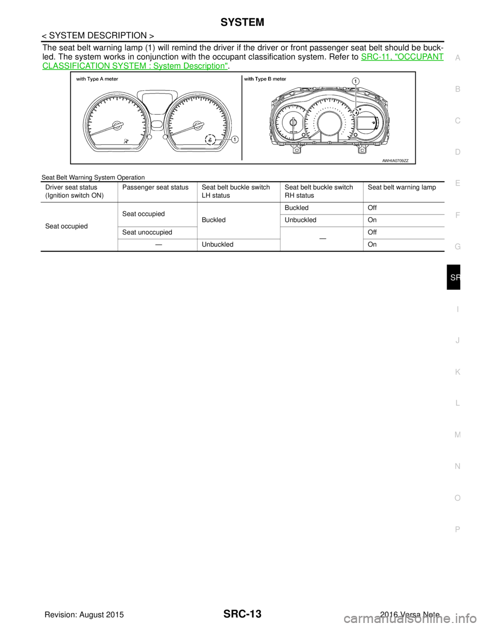
The seat belt warning lamp (1) will remind the driver if the driver or front passenger seat belt should be buck-
led. The system works in conjunction with the occupant classification system. Refer to SRC-11, "
OCCUPANT
CLASSIFICATION SYSTEM : System Description".
Seat Belt Warning System Operation
AWHIA0709ZZ
Driver seat status
(Ignition switch ON)Passenger seat status Seat belt buckle switch
LH status Seat belt buckle switch
RH status Seat belt warning lamp
Seat occupied Seat occupied
Buckled Buckled
Off
Unbuckled On
Seat unoccupied —Off
— Unbuckled On
Revision: August 2015 2016 Versa Note
cardiagn.com