push-button ignition switch NISSAN NOTE 2016 Service Owner's Guide
[x] Cancel search | Manufacturer: NISSAN, Model Year: 2016, Model line: NOTE, Model: NISSAN NOTE 2016Pages: 3641, PDF Size: 28.72 MB
Page 1674 of 3641
EXL-22
< SYSTEM DESCRIPTION >
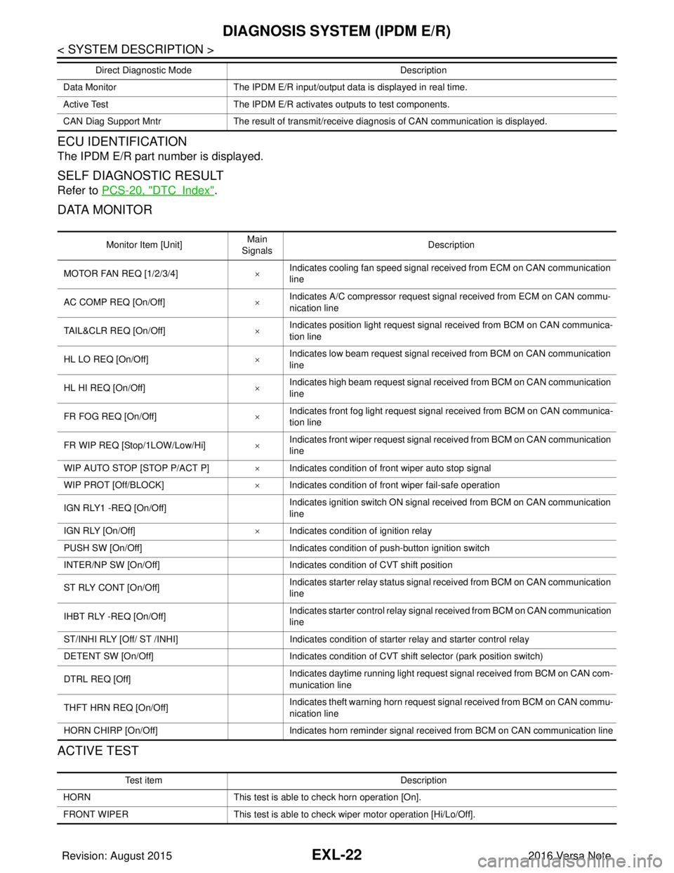
DIAGNOSIS SYSTEM (IPDM E/R)
ECU IDENTIFICATION
The IPDM E/R part number is displayed.
SELF DIAGNOSTIC RESULT
Refer to PCS-20, "DTCIndex".
DATA MONITOR
ACTIVE TEST
Data Monitor The IPDM E/R input/output data is displayed in real time.
Active Test The IPDM E/R activates outputs to test components.
CAN Diag Support Mntr The result of transmit/receive diagnosis of CAN communication is displayed.
Direct Diagnostic Mode
Description
Monitor Item [Unit]Main
Signals Description
MOTOR FAN REQ [1/2/3/4] ×Indicates cooling fan speed signal received from ECM on CAN communication
line
AC COMP REQ [On/Off] ×Indicates A/C compressor request signal received from ECM on CAN commu-
nication line
TAIL&CLR REQ [On/Off] ×Indicates position light request signal received from BCM on CAN communica-
tion line
HL LO REQ [On/Off] ×Indicates low beam request signal received from BCM on CAN communication
line
HL HI REQ [On/Off] ×Indicates high beam request signal received from BCM on CAN communication
line
FR FOG REQ [On/Off] ×Indicates front fog light request signal received from BCM on CAN communica-
tion line
FR WIP REQ [Stop/1LOW/Low/Hi] ×Indicates front wiper request signal received from BCM on CAN communication
line
WIP AUTO STOP [STOP P/ACT P] ×Indicates condition of front wiper auto stop signal
WIP PROT [Off/BLOCK] ×Indicates condition of front wiper fail-safe operation
IGN RLY1 -REQ [On/Off] Indicates ignition switch ON signal received from BCM on CAN communication
line
IGN RLY [On/Off] ×Indicates condition of ignition relay
PUSH SW [On/Off] Indicates condition of push-button ignition switch
INTER/NP SW [On/Off] Indicates condition of CVT shift position
ST RLY CONT [On/Off] Indicates starter relay status signal received from BCM on CAN communication
line
IHBT RLY -REQ [On/Off] Indicates starter control relay signal received from BCM on CAN communication
line
ST/INHI RLY [Off/ ST /INHI] Indicates condition of starter relay and starter control relay
DETENT SW [On/Off] Indicates condition of CVT shift selector (park position switch)
DTRL REQ [Off] Indicates daytime running light request signal received from BCM on CAN com-
munication line
THFT HRN REQ [On/Off] Indicates theft warning horn request signal received from BCM on CAN commu-
nication line
HORN CHIRP [On/Off] Indicates horn reminder signal received from BCM on CAN communication line
Te s t i t e m D e s c r i p t i o n
HORN This test is able to check horn operation [On].
FRONT WIPER This test is able to check wiper motor operation [Hi/Lo/Off].
Revision: August 2015 2016 Versa Note
cardiagn.com
Page 2096 of 3641
INL-2
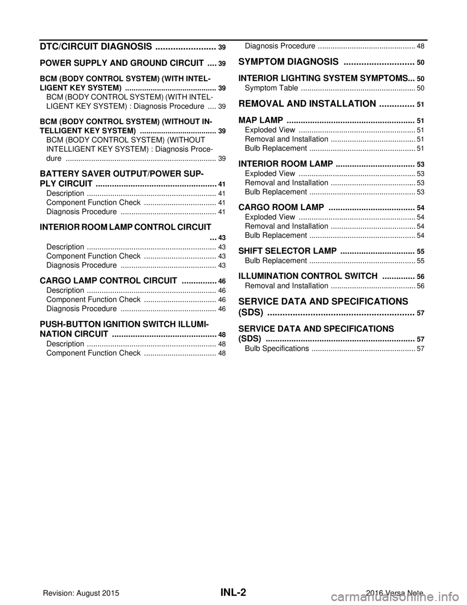
DTC/CIRCUIT DIAGNOSIS ...................... ...39
POWER SUPPLY AND GROUND CIRCUIT .. ...39
BCM (BODY CONTROL SYSTEM) (WITH INTEL-
LIGENT KEY SYSTEM) ..... .......................................
39
BCM (BODY CONTROL S YSTEM) (WITH INTEL-
LIGENT KEY SYSTEM) : Dia gnosis Procedure .....
39
BCM (BODY CONTROL SYST EM) (WITHOUT IN-
TELLIGENT KEY SYSTEM) . ....................................
39
BCM (BODY CONTROL SYSTEM) (WITHOUT
INTELLIGENT KEY SYSTEM) : Diagnosis Proce-
dure ..................................................................... ...
39
BATTERY SAVER OUTPUT/POWER SUP-
PLY CIRCUIT .....................................................
41
Description ........................................................... ...41
Component Function Check ...................................41
Diagnosis Procedure ..............................................41
INTERIOR ROOM LAMP CONTROL CIRCUIT
...
43
Description ........................................................... ...43
Component Function Check ...................................43
Diagnosis Procedure ..............................................43
CARGO LAMP CONTROL CIRCUIT ................46
Description ........................................................... ...46
Component Function Check ...................................46
Diagnosis Procedure ..............................................46
PUSH-BUTTON IGNITION SWITCH ILLUMI-
NATION CIRCUIT ..............................................
48
Description ........................................................... ...48
Component Function Check ...................................48
Diagnosis Procedure ............................................ ...48
SYMPTOM DIAGNOSIS ............................50
INTERIOR LIGHTING SYSTEM SYMPTOMS ...50
Symptom Table .................................................... ...50
REMOVAL AND INSTALLATION ..............51
MAP LAMP ........................................................51
Exploded View ..................................................... ...51
Removal and Installation .........................................51
Bulb Replacement ................................................ ...51
INTERIOR ROOM LAMP ...................................53
Exploded View ..................................................... ...53
Removal and Installation .........................................53
Bulb Replacement ................................................ ...53
CARGO ROOM LAMP ......................................54
Exploded View ..................................................... ...54
Removal and Installation .........................................54
Bulb Replacement ................................................ ...54
SHIFT SELECTOR LAMP .................................55
Bulb Replacement ...................................................55
ILLUMINATION CONTROL SWITCH ...............56
Removal and Installation .........................................56
SERVICE DATA AND SPECIFICATIONS
(SDS) .......... ................................. ...............
57
SERVICE DATA AND SPECIFICATIONS
(SDS) .............................................................. ...
57
Bulb Specifications ............................................... ...57
Revision: August 2015 2016 Versa Note
cardiagn.com
Page 2100 of 3641
INL-6
< SYSTEM DESCRIPTION >
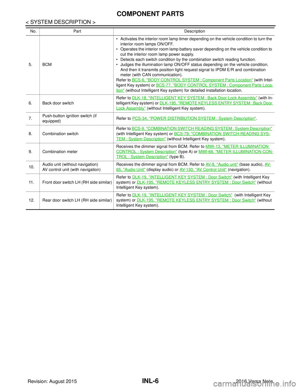
COMPONENT PARTS
5. BCM• Activates the interior room lamp timer depending on the vehicle condition to turn the
interior room lamps ON/OFF.
• Operates the interior room lamp battery saver depending on the vehicle condition to cut the interior room lamp power supply.
• Detects each switch condition by the combination switch reading function.
• Judges the illumination lamp ON/OFF status depending on the vehicle condition.
And then it transmits position light request signal to IPDM E/R and combination
meter (with CAN communication).
Refer to BCS-6, "
BODY CONTROL SYSTEM : Component Part s Location" (with Intel-
ligent Key system) or BCS-77, "
BODY CONTROL SYSTEM : Component Parts Loca-
tion" (without Intelligent Key system) for detailed installation location.
6. Back door switch Refer to DLK-18, "
INTELLIGENT KEY SYSTEM : Ba
ck Door Lock Assembly" (with In-
telligent Key system) or DLK-195, "
REMOTE KEYLESS ENTRY SYSTEM : Back Door
Lock Assembly" (without Intelligent Key system).
7. Push-button ignition switch (if
equipped) Refer to PCS-34, "
POWER DISTRIBUTION SYSTEM : System Description".
8. Combination switch Refer to
BCS-9, "
COMBINATION SWITCH READING SY STEM : System Description"
(with Intelligent Key system) or BCS-79, "
COMBINATION SWITCH READING SYS-
TEM : System Description" (without Intelligent Key system).
9. Combination meter Receives the dimmer signal from BCM. Refer to
MWI-13, "
METER ILLUMINATION
CONTROL : System Description" (type A) or MWI-66, "METER ILLUMINATION CON-
TROL : System Description" (type B).
10. Audio unit (without navigation)
AV control unit (with navigation) Receives the dimmer signal from BCM. Refer to
AV- 8 , "
Audio unit" (base audio), AV-
65, "Audio Unit" (display audio) or AV- 1 3 0 , "AV Control Unit" (navigation).
11. Front door switch LH (RH side similar) Refer to DLK-19, "
INTELLIGENT KEY SYSTEM : Door Switch" (with Intelligent Key
system) or DLK-195, "
REMOTE KEYLESS ENTRY SYSTEM : Door Switch" (without
Intelligent Key system).
12. Rear door switch LH (RH side similar) Refer to DLK-19, "
INTELLIGENT KEY SYSTEM : Door Switch" (with Intelligent Key
system) or DLK-195, "
REMOTE KEYLESS ENTRY SYSTEM : Door Switch" (without
Intelligent Key system).
No.
Part Description
Revision: August 2015 2016 Versa Note
cardiagn.com
Page 2102 of 3641
INL-8
< SYSTEM DESCRIPTION >
SYSTEM
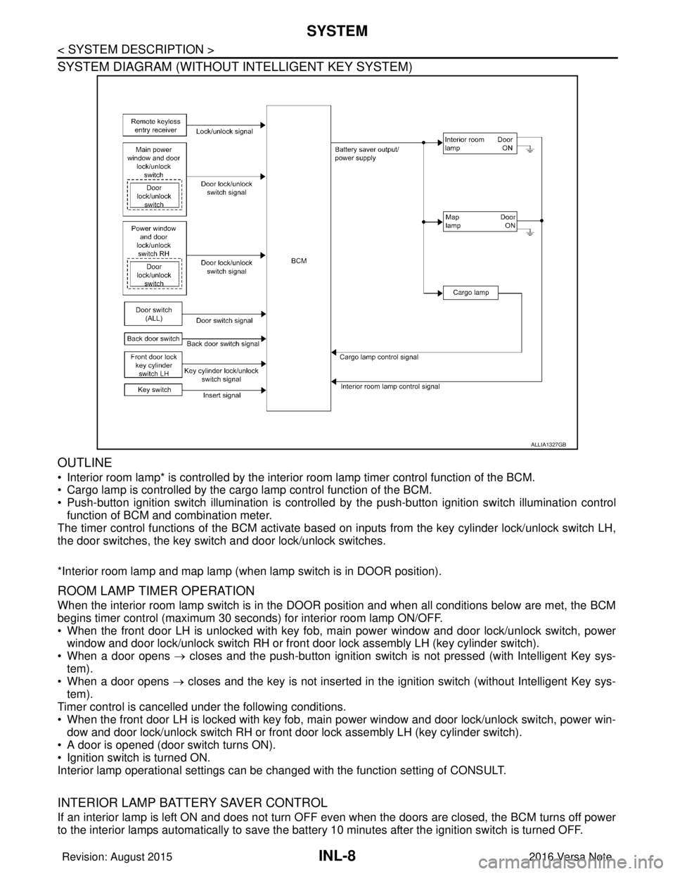
SYSTEM DIAGRAM (WITHOUT INTELLIGENT KEY SYSTEM)
OUTLINE
• Interior room lamp* is controlled by the interior room lamp timer control function of the BCM.
• Cargo lamp is controlled by the cargo lamp control function of the BCM.
• Push-button ignition switch illumination is controlled by the push-button ignition switch illumination control
function of BCM and combination meter.
The timer control functions of the BCM activate based on inputs from the key cylinder lock/unlock switch LH,
the door switches, the key switch and door lock/unlock switches.
*Interior room lamp and map lamp (when lamp switch is in DOOR position).
ROOM LAMP TIMER OPERATION
When the interior room lamp switch is in the DOOR position and when all conditions below are met, the BCM
begins timer control (maximum 30 seconds) for interior room lamp ON/OFF.
• When the front door LH is unlocked with key fob, main power window and door lock/unlock switch, power
window and door lock/unlock switch RH or front door lock assembly LH (key cylinder switch).
• When a door opens → closes and the push-button ignition switch is not pressed (with Intelligent Key sys-
tem).
• When a door opens → closes and the key is not inserted in the ignition switch (without Intelligent Key sys-
tem).
Timer control is cancelled under the following conditions.
• When the front door LH is locked with key fob, main power window and door lock/unlock switch, power win-
dow and door lock/unlock switch RH or front door lock assembly LH (key cylinder switch).
• A door is opened (door switch turns ON).
• Ignition switch is turned ON.
Interior lamp operational settings can be changed with the function setting of CONSULT.
INTERIOR LAMP BATTERY SAVER CONTROL
If an interior lamp is left ON and does not turn OFF even when the doors are closed, the BCM turns off power
to the interior lamps automatically to save the batte ry 10 minutes after the ignition switch is turned OFF.
ALLIA1327GB
Revision: August 2015 2016 Versa Note
cardiagn.com
Page 2106 of 3641
INL-12
< SYSTEM DESCRIPTION >
DIAGNOSIS SYSTEM (BCM) (WITH INTELLIGENT KEY SYSTEM)
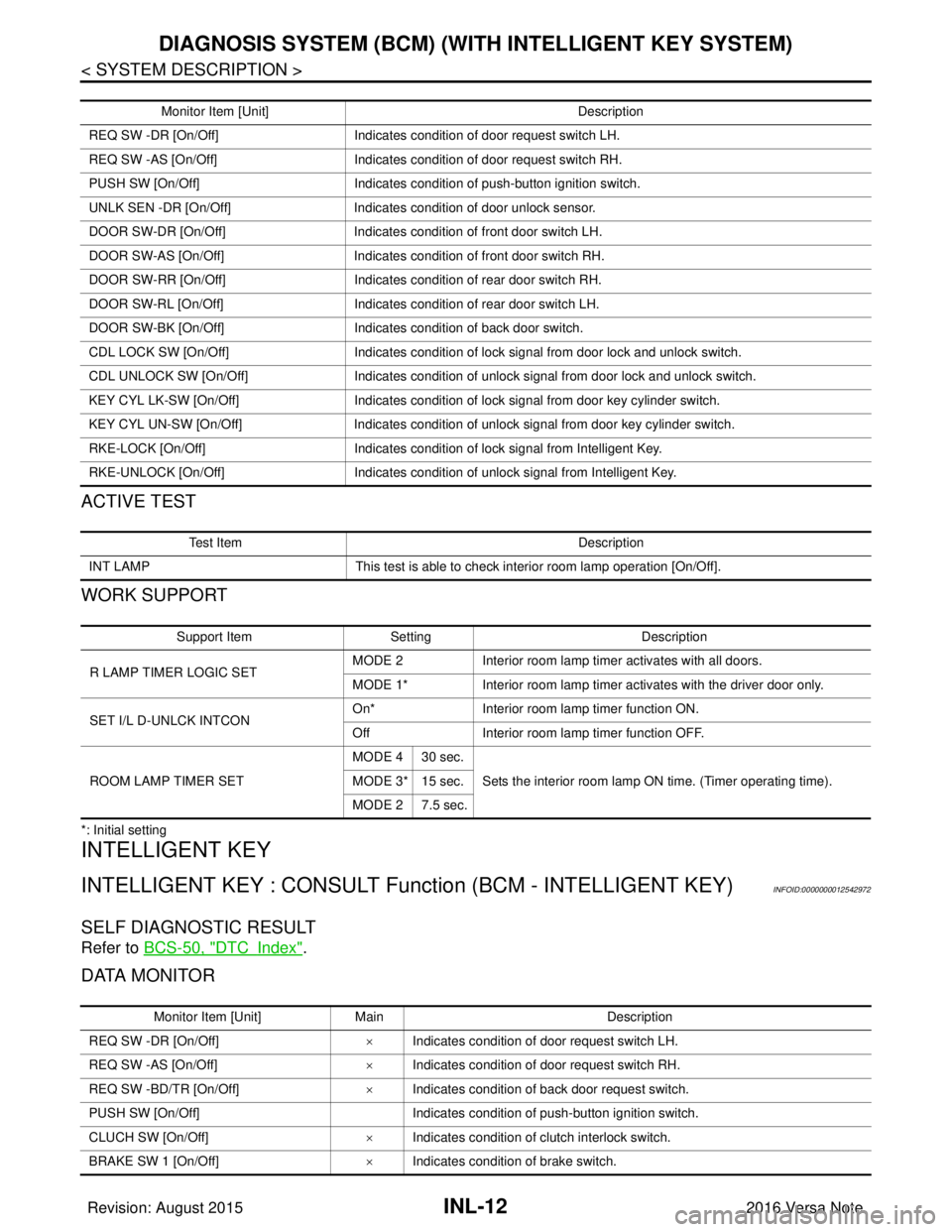
ACTIVE TEST
WORK SUPPORT
*: Initial setting
INTELLIGENT KEY
INTELLIGENT KEY : CONSULT Function (BCM - INTELLIGENT KEY)INFOID:0000000012542972
SELF DIAGNOSTIC RESULT
Refer to BCS-50, "DTCIndex".
DATA MONITOR
Monitor Item [Unit] Description
REQ SW -DR [On/Off] Indicates condition of door request switch LH.
REQ SW -AS [On/Off] Indicates condition of door request switch RH.
PUSH SW [On/Off] Indicates condition of push-button ignition switch.
UNLK SEN -DR [On/Off] Indicates condition of door unlock sensor.
DOOR SW-DR [On/Off] Indicates condition of front door switch LH.
DOOR SW-AS [On/Off] Indicates condition of front door switch RH.
DOOR SW-RR [On/Off] Indicates condition of rear door switch RH.
DOOR SW-RL [On/Off] Indicates condition of rear door switch LH.
DOOR SW-BK [On/Off] Indicates condition of back door switch.
CDL LOCK SW [On/Off] Indicates condition of lock signal from door lock and unlock switch.
CDL UNLOCK SW [On/Off] Indicates condition of unlock signal from door lock and unlock switch.
KEY CYL LK-SW [On/Off] Indicates condition of lock signal from door key cylinder switch.
KEY CYL UN-SW [On/Off] Indicates condition of unlock signal from door key cylinder switch.
RKE-LOCK [On/Off] Indicates condition of lock signal from Intelligent Key.
RKE-UNLOCK [On/Off] Indicates condition of unlock signal from Intelligent Key.
Te s t I t e m D e s c r i p t i o n
INT LAMP This test is able to check interior room lamp operation [On/Off].
Support ItemSetting Description
R LAMP TIMER LOGIC SET MODE 2
Interior room lamp timer activates with all doors.
MODE 1* Interior room lamp timer activates with the driver door only.
SET I/L D-UNLCK INTCON On*
Interior room lamp timer function ON.
Off Interior room lamp timer function OFF.
ROOM LAMP TIMER SET MODE 4 30 sec.
Sets the interior room lamp ON time. (Timer operating time).
MODE 3* 15 sec.
MODE 2 7.5 sec.
Monitor Item [Unit] Main Description
REQ SW -DR [On/Off] ×Indicates condition of door request switch LH.
REQ SW -AS [On/Off] ×Indicates condition of door request switch RH.
REQ SW -BD/TR [On/Off] ×Indicates condition of back door request switch.
PUSH SW [On/Off] Indicates condition of push-button ignition switch.
CLUCH SW [On/Off] ×Indicates condition of clutch interlock switch.
BRAKE SW 1 [On/Off] ×Indicates condition of brake switch.
Revision: August 2015 2016 Versa Note
cardiagn.com
Page 2107 of 3641

DIAGNOSIS SYSTEM (BCM) (WITH INTELLIGENT KEY SYSTEM)
INL-13
< SYSTEM DESCRIPTION >
C
D E
F
G H
I
J
K
M A
B
INL
N
O P
ACTIVE TEST
BRAKE SW 2 [On/Off] Indicates condition of brake switch.
DETE/CANCL SW [On/Off] ×Indicates condition of P (park) position.
SFT PN/N SW [On/Off] ×Indicates condition of P (park) or N (neutral) position.
UNLK SEN -DR [On/Off] ×Indicates condition of door unlock sensor.
PUSH SW -IPDM [On/Off] Indicates condition of push-button ignition switch received from IPDM E/R on
CAN communication line.
IGN RLY1 -F/B [On/Off] Indicates condition of ignition relay 1 received from IPDM E/R on CAN commu-
nication line.
DETE SW -IPDM [On/Off] Indicates condition of detent switch received from TCM on CAN communication
line.
SFT PN -IPDM [On/Off] Indicates condition of P (park) or N (neutral) position from TCM on CAN com-
munication line.
SFT P -MET [On/Off] Indicates condition of P (park) position from TCM on CAN communication line.
SFT N -MET [On/Off] Indicates condition of N (neutral) position from IPDM E/R on CAN communica-
tion line.
ENGINE STATE [Stop/Start/Crank/Run] ×Indicates condition of engine state from ECM on CAN communication line.
VEH SPEED 1 [mph/km/h] ×Indicates condition of vehicle speed si
gnal received from ABS on CAN commu-
nication line.
VEH SPEED 2 [mph/km/h] ×Indicates condition of vehicle speed signal received from combination meter on
CAN communication line.
DOOR STAT -DR [LOCK/READY/UNLK] ×Indicates condition of driver side door status.
DOOR STAT -AS [LOCK/READY/UNLK] ×Indicates condition of passenger side door status.
ID OK FLAG [Set/Reset] Indicates condition of Intelligent Key ID.
PRMT ENG STRT [Set/Reset] Indicates condition of engine start possibility.
RKE OPE COUN1 [0-19] ×When remote keyless entry receiver receives the signal transmitted while oper-
ating on Intelligent Key, the numerical value start changing.
RKE OPE COUN2 [0-19] ×When remote keyless entry receiver receives the signal transmitted while oper-
ating on Intelligent Key, the numerical value start changing.
RKE-LOCK [On/Off] Indicates condition of lock signal from Intelligent Key.
RKE-UNLOCK [On/Off] Indicates condition of unlock signal from Intelligent Key.
RKE-PANIC [On/Off] Indicates condition of panic signal from Intelligent Key.
RKE-MODE CHG [On/Off] Indicates condition of mode change signal from Intelligent Key.
Monitor Item [Unit]
Main Description
Test Item Description
INSIDE BUZZER This test is able to check combination meter warning chime operation [Take Out/Knob/Key/
Off].
LCD This test is able to check combination me
ter display information [Off/LK WN/OUTKEY/NO
KY/BATT/INSRT/SFT P/ROTAT/ID NG/B&P I/B&P N].
BATTERY SAVER This test is able to check battery saver operation [On/Off].
ENGINE SW ILLUMI This test is able to check push-button ignition switch START indicator operation [On/Off].
PUSH SWITCH INDICATOR This test is able to check push-button ignition switch indicator operation [On/Off].
INT LAMP This test is able to check interior room lamp operation [On/Off].
INDICATOR This test is able to check combination mete r warning lamp operation [KEY ON/KEY IND/Off].
FLASHER This test is able to check hazard lamp operation [LH/RH/Off].
OUTSIDE BUZZER This test is able to check Intelligent Key warning buzzer operation [On/Off].
HORN This test is able to check horn operation [On].
P RANGE This test is able to check CVT shift selector illumination operation [On/Off].
Revision: August 2015 2016 Versa Note
cardiagn.com
Page 2109 of 3641

DIAGNOSIS SYSTEM (BCM) (WITH INTELLIGENT KEY SYSTEM)
INL-15
< SYSTEM DESCRIPTION >
C
D E
F
G H
I
J
K
M A
B
INL
N
O P
ACTIVE TEST
WORK SUPPORT
*: Initial setting Monitor Item [Unit]
Description
REQ SW -DR [On/Off] Indicates condition of door request switch LH.
REQ SW -AS [On/Off] Indicates condition of door request switch RH.
PUSH SW [On/Off] Indicates condition push-button ignition switch.
UNLK SEN -DR [On/Off] Indicates condition of door unlock sensor.
DOOR SW-DR [On/Off] Indicates condition of front door switch LH.
DOOR SW-AS [On/Off] Indicates condition of front door switch RH.
DOOR SW-RR [On/Off] Indicates condition of rear door switch RH.
DOOR SW-RL [On/Off] Indicates condition of rear door switch LH.
DOOR SW-BK [On/Off] Indicates condition of back door switch.
CDL LOCK SW [On/Off] Indicates condition of lock signal from door lock and unlock switch.
CDL UNLOCK SW [On/Off] Indicates condition of unlock signal from door lock and unlock switch.
KEY CYL LK-SW [On/Off] Indicates condition of lock signal from door key cylinder switch.
KEY CYL UN-SW [On/Off] Indicates condition of unlock signal from door key cylinder switch.
RKE-LOCK [On/Off] Indicates condition of lock signal from Intelligent Key.
RKE-UNLOCK [On/Off] Indicates condition of unlock signal from Intelligent Key.
Test item Description
BATTERY SAVER This test is able to check battery saver operation [On/Off].
Support ItemSetting Description
BATTERY SAVER SET ON*
Exterior lamp battery saver function ON.
OFF Exterior lamp battery saver function OFF.
ROOM LAMP TIMER SET MODE 3* 10 min.
Sets interior room lamp battery saver timer operating time.
MODE 2 60 min.
MODE 1 15 min.
Revision: August 2015 2016 Versa Note
cardiagn.com
Page 2142 of 3641
INL-48
< DTC/CIRCUIT DIAGNOSIS >
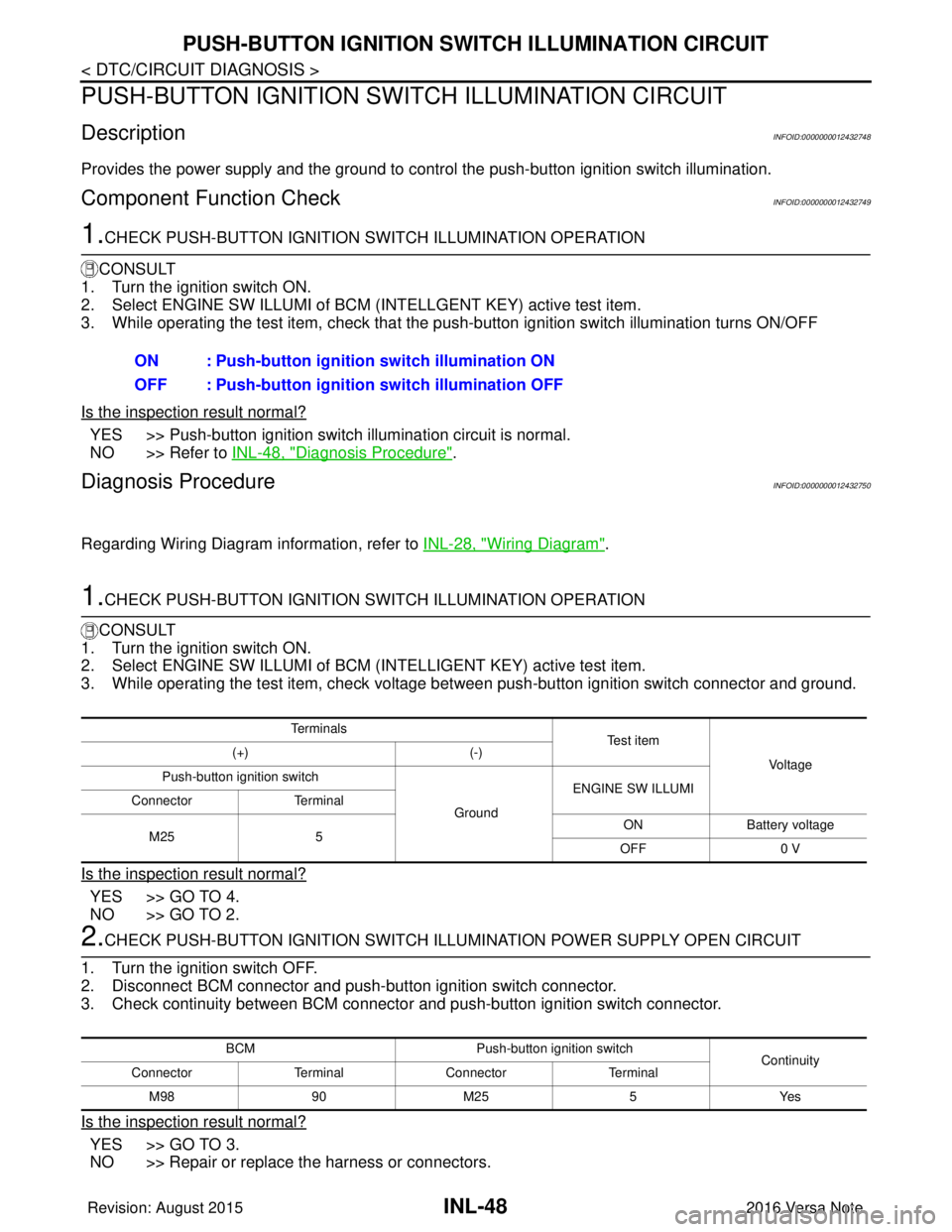
PUSH-BUTTON IGNITION SWITCH ILLUMINATION CIRCUIT
PUSH-BUTTON IGNITION SWITCH ILLUMINATION CIRCUIT
DescriptionINFOID:0000000012432748
Provides the power supply and the ground to control the push-button ignition switch illumination.
Component Function CheckINFOID:0000000012432749
1.CHECK PUSH-BUTTON IGNITION SWITCH ILLUMINATION OPERATION
CONSULT
1. Turn the ignition switch ON.
2. Select ENGINE SW ILLUMI of BCM (I NTELLGENT KEY) active test item.
3. While operating the test item, check that the push-button ignition switch illumination turns ON/OFF
Is the inspection result normal?
YES >> Push-button ignition switch illumination circuit is normal.
NO >> Refer to INL-48, "
Diagnosis Procedure".
Diagnosis ProcedureINFOID:0000000012432750
Regarding Wiring Diagram information, refer to INL-28, "Wiring Diagram".
1.CHECK PUSH-BUTTON IGNITION SWITCH ILLUMINATION OPERATION
CONSULT
1. Turn the ignition switch ON.
2. Select ENGINE SW ILLUMI of BCM (INTELLIGENT KEY) active test item.
3. While operating the test item, check voltage bet ween push-button ignition switch connector and ground.
Is the inspection result normal?
YES >> GO TO 4.
NO >> GO TO 2.
2.CHECK PUSH-BUTTON IGNITION SWITCH ILLUMINATION POWER SUPPLY OPEN CIRCUIT
1. Turn the ignition switch OFF.
2. Disconnect BCM connector and push-button ignition switch connector.
3. Check continuity between BCM connector and push-button ignition switch connector.
Is the inspection result normal?
YES >> GO TO 3.
NO >> Repair or replace the harness or connectors. ON : Push-button ignition switch illumination ON
OFF : Push-button ignition
switch illumination OFF
Te r m i n a l s
Te s t i t e m
Vo l ta g e
(+)
(-)
Push-button ignition switch
GroundENGINE SW ILLUMI
Connector Terminal
M25 5 ON
Battery voltage
OFF 0 V
BCM Push-button ignition switch
Continuity
Connector TerminalConnector Terminal
M 989 0M 25 5 Y es
Revision: August 2015 2016 Versa Note
cardiagn.com
Page 2143 of 3641
PUSH-BUTTON IGNITION SWITCH ILLUMINATION CIRCUITINL-49
< DTC/CIRCUIT DIAGNOSIS >
C
DE
F
G H
I
J
K
M A
B
INL
N
O P
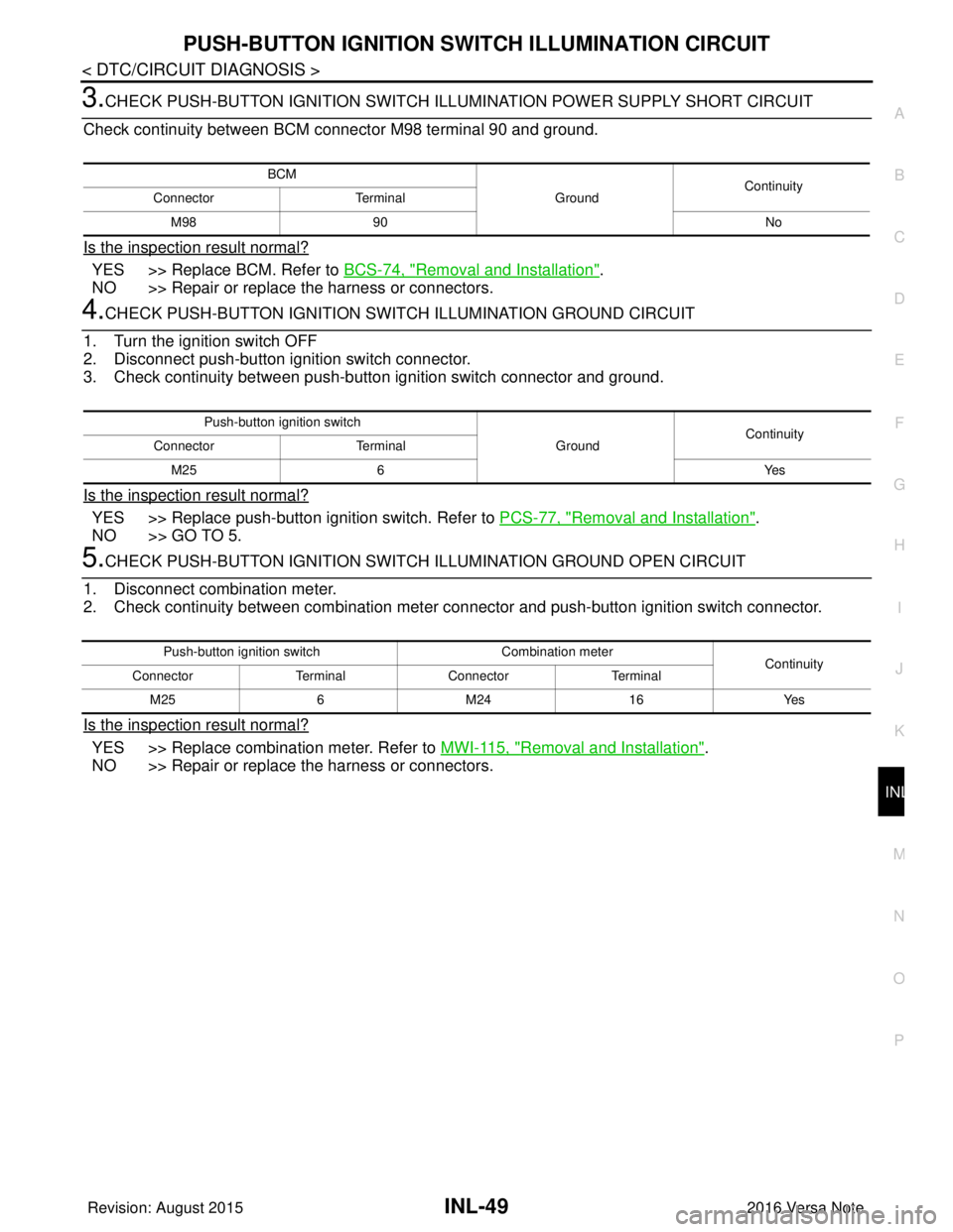
3.CHECK PUSH-BUTTON IGNITION SWITCH ILLUMINATION POWER SUPPLY SHORT CIRCUIT
Check continuity between BCM connector M98 terminal 90 and ground.
Is the inspection result normal?
YES >> Replace BCM. Refer to BCS-74, "Removal and Installation".
NO >> Repair or replace the harness or connectors.
4.CHECK PUSH-BUTTON IGNITION SWIT CH ILLUMINATION GROUND CIRCUIT
1. Turn the ignition switch OFF
2. Disconnect push-button ignition switch connector.
3. Check continuity between push-butt on ignition switch connector and ground.
Is the inspection result normal?
YES >> Replace push-button ignition switch. Refer to PCS-77, "Removal and Installation".
NO >> GO TO 5.
5.CHECK PUSH-BUTTON IGNITION SWITCH ILLUMINATION GROUND OPEN CIRCUIT
1. Disconnect combination meter.
2. Check continuity between combination meter connector and push-button ignition switch connector.
Is the inspection result normal?
YES >> Replace combination meter. Refer to MWI-115, "Removal and Installation".
NO >> Repair or replace the harness or connectors.
BCM
GroundContinuity
Connector Terminal
M98 90 No
Push-button ignition switch
GroundContinuity
Connector Terminal
M25 6 Yes
Push-button ignition switchCombination meter
Continuity
Connector TerminalConnector Terminal
M25 6M24 16 Yes
Revision: August 2015 2016 Versa Note
cardiagn.com
Page 2219 of 3641

LAN
SYSTEMLAN-31
< SYSTEM DESCRIPTION > [CAN]
C
D
E
F
G H
I
J
K L
B A
O P
N
Vehicle speed signal (ABS)
TR R R R R
Brake warning lamp signal TR
Detention switch signal TR
Front wiper stop position signal TR
High beam status signal RT
Ignition switch ON signal TR
RT
Interlock/PNP switch signal TR
RT
Low beam status signal RT
Push-button ignition switch status signal TR
OD OFF indicator signal RT
RT
Starter control relay signal TR
RT
Starter relay status signal TR
RT
Sleep-ready signal TR
TR
Wake up signal TR
Input shaft revolution signal RT
O/D OFF indicator signal TR
Output shaft revolution signal RT
Shift position signal RT RR
Target gear ratio signal RT
EPS warning lamp signal TR
Overdrive control switch signal RT
Fuel filler cap warning reset signal RT
O/D OFF switch signal RT
Odometer signal TR
Vehicle speed signal (Meter) RR TR
Wake up signal TR
Steering angle sensor signal RR T
A/C ON signal R T
Blower fan ON signal R T
Buzzer output signal RT
Dimmer signal RT
Door switch signal RRT
Engine start operation indicator lamp signal RT
Front wiper request signal RT
High beam request signal RRT
Key warning lamp signal RT
Low beam request signal RRT
Signal name
ECM
ABS
IPDM-E
TCMAV M
EPS
M&A
STRG
BCM
Revision: August 2015 2016 Versa Note
cardiagn.com