push-button ignition switch NISSAN NOTE 2016 Service User Guide
[x] Cancel search | Manufacturer: NISSAN, Model Year: 2016, Model line: NOTE, Model: NISSAN NOTE 2016Pages: 3641, PDF Size: 28.72 MB
Page 289 of 3641

BCS-28
< SYSTEM DESCRIPTION >[WITH INTELLIGENT KEY SYSTEM]
DIAGNOSIS SYSTEM (BCM)
RETAINED PWR
RETAINED PWR : CONSULT Function (BCM - RETAINED PWR)INFOID:0000000012432328
DATA MONITOR
SIGNAL BUFFER
SIGNAL BUFFER : CONSULT Func
tion (BCM - SIGNAL BUFFER)INFOID:0000000012432329
DATA MONITOR
AIR PRESSURE MONITOR
AIR PRESSURE MONITOR : CONSULT Fu nction (BCM - AIR PRESSURE MONI-
TOR)
INFOID:0000000012432330
NOTE:
The Signal Tech II Tool [– (J-50190)] can be used to perform the following functions. Refer to the Signal Tech
II User Guide for additional information.
• Activate and display TPMS transmitter IDs
• Display tire pressure reported by the TPMS transmitter
• Read TPMS DTCs
• Register TPMS transmitter IDs
• Check Intelligent Key relative signal strength
• Confirm vehicle Intelligent Key antenna signal strength
SELF DIAGNOSTIC RESULT
NOTE:
Before performing self diagnostic result, be sure to register the ID, or else the actual malfunction may be differ-
ent from that displayed on CONSULT.
Refer to BCS-50, "
DTCIndex".
DATA MONITOR
ACTIVE TEST
Monitor Item [Unit] Description
DOOR SW-DR [On/Off] Indicates condition of front door switch LH.
DOOR SW-AS [On/Off] Indicates condition of front door switch RH.
Monitor Item [Unit] Description
PUSH SW [On/Off] Indicates condition of the push-button ignition switch.
Monitor Item [Unit] Description
AIR PRESS FL [kPa, kg/cm
2 or Psi] Indicates air pressure of front LH tire.
AIR PRESS FR [kPa, kg/cm
2 or Psi] Indicates air pressure of front RH tire.
AIR PRESS RR [kPa, kg/cm
2 or Psi] Indicates air pressure of rear RH tire.
AIR PRESS RL [kPa, kg/cm
2 or Psi] Indicates air pressure of rear LH tire.
ID REGST FL1 [Done/Yet] Indicates ID registration status of front LH transmitter.
ID REGST FR1 [Done/Yet] Indicates ID registration status of front RH transmitter.
ID REGST RR1 [Done/Yet] Indicates ID registration status of rear RH transmitter.
ID REGST RL1 [Done/Yet] Indicates ID registration status of rear LH transmitter.
WARNING LAMP [Off/On] Indicates condition of low tire pressure warning lamp in combination meter.
BUZZER [Off/On] Indicates condition of buzzer in combination meter.
Revision: August 2015 2016 Versa Note
cardiagn.com
Page 297 of 3641

BCS-36
< ECU DIAGNOSIS INFORMATION >[WITH INTELLIGENT KEY SYSTEM]
BCM
8
(GR) Ground Key cylinder lock sw
signal
InputKey cylinder
switch N position
7.0 - 8.0 V
LOCK position 0 V
9
(LG) Ground Stop lamp switch 1 Input Stop lamp
switchOFF (Brake pedal
released)
0 V
ON (Brake pedal
depressed) Battery voltage
12
(GR) Ground
Central door lock sw
signal Input
Door lock and
unlock switch NEUTRAL position
1.0 - 1.5 V
LOCK position 0 V
13
(BR) Ground
Central door unlock
sw signal Input
Door lock and
unlock switch NEUTRAL position
1.0 - 1.5 V
UNLOCK position 0 V
15
(G) Ground Rear defogger
switch signal
InputRear window
defogger switch Not pressed
1.0 - 1.5 V
Pressed 0 V
18
(V) Ground
Keyless tuner
ground Input Push-button ignition switch ON
0 V
Te r m i n a l N o .
(Wire color) Description
Condition Va l u e
(Approx.)
Signal name Input/
Output
+ −
PKIB4960J
JPMIA0012GB
JPMIA0012GB
JPMIA0012GB
Revision: August 2015 2016 Versa Note
cardiagn.com
Page 298 of 3641

BCS
BCM
BCS-37
< ECU DIAGNOSIS INFORMATION > [WITH INTELLIGENT KEY SYSTEM]
C
D
E
F
G H
I
J
K L
B A
O P
N19
(LG) Ground
Keyless tuner power
supply OutputPush-button ignition switch OFF
Push-button ignition switch ACC or ON
5 V
20
(G) Ground Keyless tuner signal Input Push-button ig-
nition switch
OFFWaiting
When operating either
button on Intelligent Key
21
(P) Ground Immobilizer one way
communication
(CLOCK) signal Input/
Output Intelligent Key
battery is re-
moved Brake pedal depressed
NOTE:
Waveform varies each
time when brake pedal is
depressed
Brake pedal released
Battery voltage
22
(W) Ground Keyless tuner RSSI
signal
InputPush-button ig-
nition switch
OFF Waiting
When pressing and hold-
ing either button on Intelli-
gent Key
Te r m i n a l N o .
(Wire color) Description
Condition Va l u e
(Approx.)
Signal name Input/
Output
+ −
JMKIA3838GB
JMKIA3838GB
JMKIA3841GB
JMKIA6232JP
JMKIA5952GB
JMKIA5953GB
Revision: August 2015 2016 Versa Note
cardiagn.com
Page 299 of 3641

BCS-38
< ECU DIAGNOSIS INFORMATION >[WITH INTELLIGENT KEY SYSTEM]
BCM
23
(GR) Ground Security indicator
output
OutputSecurity indica-
tor lamp ON
0 – 0.5 V
Blinking (push-button igni-
tion switch OFF) 12.0 V
OFF Battery voltage
24
(SB) Ground Audio dongle link
(SERIAL) Input/
Output Push-button ignition switch OFF
5 V
25
(LG) Ground Immobilizer two way
communication sig-
nal Input/
Output During waiting Brake pedal depressed
NOTE:
Waveform varies each
time when brake pedal is
depressed
Brake pedal released
Battery voltage
26
(O) Ground THERMO amp. sig-
nal
InputPush-button ig-
nition switch ON
and blower fan
switch ON A/C switch OFF
Battery voltage
A/C switch ON 0 V
27
(V) Ground Air con sw signal Input Push-button ig-
nition switch ON
and blower fan
switch ONA/C switch OFF
Battery voltage
A/C switch ON 0 V
28
(SB) Ground Blower fan sw signal Input Fan switch OFF
0 V
ON 7.0 - 8.0 V
29
(BG) Ground Hazard sw signal Input Hazard switch OFF
Battery voltage
ON 0 – 1.5 V
31
(Y) Ground
Driver door lock sta-
tus Input Front door LH LOCK status
11 . 8 V
UNLOCK status 0V
Te r m i n a l N o .
(Wire color) Description
Condition Va l u e
(Approx.)
Signal name Input/
Output
+ −
JPMIA0590GB
JMKIA6233JP
PKIB4960J
JPMIA0011GB
Revision: August 2015 2016 Versa Note
cardiagn.com
Page 303 of 3641

BCS-42
< ECU DIAGNOSIS INFORMATION >[WITH INTELLIGENT KEY SYSTEM]
BCM
55
(G) Ground Door unlock output
(RR, RL)
Output Rear doors UNLOCK (Actuator is acti-
vated)
Battery voltage
Actuator is not activated 0 V
56
(W) Ground Battery saver output Output Interior room lamp battery saver timed out
0 V
Except when interior room lamp battery sav-
er timed out Battery voltage
57
(Y) Ground Battery power sup-
ply Input Push-button ignition switch OFF
Battery voltage
59
(G) Ground Door unlock output
(AS)
Output Front RH door UNLOCK (Actuator is acti-
vated)
Battery voltage
Actuator is not activated 0 V
60
(V) Ground Flasher output
(LEFT)
OutputPush-button ig-
nition switch ON Turn signal switch OFF
0 V
Turn signal switch LH 6.5 V
61
(W) Ground Flasher output
(RIGHT)
OutputPush-button ig-
nition switch ON Turn signal switch OFF
0 V
Turn signal switch RH 6.5 V
63
(R) Ground Room lamp control Output
Interior room
lampOFF
Battery voltage
ON 0 – 1.0 V
65
(SB) Ground Door lock output Output All doors LOCK (Actuator is activat-
ed)
Battery voltage
Actuator is not activated 0 V
66
(G) Ground
Door unlock output
(DR) Output Front LH door UNLOCK (Actuator is acti-
vated)
Battery voltage
Actuator is not activated 0 V
67
(B) Ground Ground
Output Push-button ignition switch ON 0 V
68
(L) Ground Power window pow-
er supply (RAP)
Output Push-button ignition switch ON
Battery voltage
70
(G) Ground
Battery power sup-
ply Input Push-button ignition switch OFF
Battery voltage
72
(L) Ground A/C indicator
Input— —
75
(GR) Ground
Request sw (DR)
signal In
put Drive
r
door re-
quest switch ON (Pressed)
0 – 1.5 V
OFF (Not pressed) Battery voltage
Te r m i n a l N o .
(Wire color) Description
Condition Va l u e
(Approx.)
Signal name Input/
Output
+ −
PKIC6370E
PKIC6370E
Revision: August 2015 2016 Versa Note
cardiagn.com
Page 308 of 3641

BCS
BCM
BCS-47
< ECU DIAGNOSIS INFORMATION > [WITH INTELLIGENT KEY SYSTEM]
C
D
E
F
G H
I
J
K L
B A
O P
N
1: With CVT
2: With M/T 90
(W) Ground Push-button ignition
switch illumination
power supply OutputPush-button ig-
nition switch il-
lumination ON
Battery voltage
OFF 0 – 1.5 V
91
(V) Ground ACC/ON indicator
lamp
OutputPush-button ig-
nition switch OFF
Battery voltage
ACC or ON 0 – 1.5 V
92
(B) Ground Push-button ignition
switch illumination
lamp Output
Push-button ig-
nition switch il-
lumination ON
5.5 V
OFF 0 – 1.5 V
93
(R) Ground Intelligent Key warn-
ing buzzer OutputIntelligent Key
warning buzzer Sounding
0 – 1.5 V
Not sounding Battery voltage
96
(SB) Ground Accessory relay
control OutputIgnition Push-
button switch OFF
0 – 0.5 V
ACC or ON Battery voltage
97
(R) Ground Starter relay control Output Push-button ig-
nition switch ONSelector lever in P (Park)
or N (Neutral) position
Battery voltage
Selector lever not in P
(Park) or N (Neutral) posi-
tion 0 – 0.5 V
98
(BG) Ground Ignition relay (IPDM
E/R) control OutputPush-button ig-
nition switch OFF or ACC
Battery voltage
ON 0 – 0.5 V
99
(GR) Ground Ignition relay (F/B)
control OutputPush-button ig-
nition switch OFF or ACC
0 – 0.5 V
ON Battery voltage
100 (L) Ground Request sw (AS)
signal InputPassenger door
request switch ON (Pressed)
0 – 1.5 V
OFF (Not pressed) Battery voltage
101 (V) Ground Clutch interlock
switch
InputClutch interlock
sw
itch OFF (c
l
utch pedal is not
depressed) 0V
ON (clutch pedal is de-
pressed) Battery voltage
102
1
(BR) Ground P/N position
Input Selector leverSelector lever in P (Park)
or N (Neutral) position
Battery voltage
Selector lever not in P
(Park) or N (Neutral) posi-
tion 0 – 1.5 V
102
2
(BR) Ground Neutral sw
Input Selector leverSelector lever in N (Neu-
tral) position
Battery voltage
Selector lever not in N
(Neutral) position 0 – 1.5 V
103
(LG) Ground Front defrost switch Input
——
104 (V) Ground CVT shift selector
(park position
switch) power sup-
ply Output Push-button ignition switch ON
Battery voltage
105
(SB) Ground Stop lamp switch 2 Input Push-button ignition switch OFF
Battery voltage
106 (Y) Ground Blower relay control Output
Push-button ig-
nition switchOFF or ACC
0 – 0.5 V
ON Battery voltage
Te r m i n a l N o .
(Wire color) Description
Condition Va l u e
(Approx.)
Signal name Input/
Output
+ −
Revision: August 2015 2016 Versa Note
cardiagn.com
Page 369 of 3641

BCS-108
< ECU DIAGNOSIS INFORMATION >[WITHOUT INTELLIGENT KEY SYSTEM]
BCM
20
(G) Ground Keyless tuner signal Input Ignition switch
OFFKey inserted into ignition
key cylinder
0 V
Waiting
Signal receiving
21
(P) Ground Immobilizer one way
communication
(clock) signal Input/
Output While waiting Turn ignition switch ON.
Turn ignition switch ON: Pointer
of tester should move.
23
(GR) Ground Security indicator
output signal
InputSecurity indica-
tor ON
0 V
Blinking (Ignition switch
OFF) 11.3 V
OFF Battery voltage
24
(SB) Ground Audio/dongle link
(serial) signal Input/
Output Ignition switch OFF.
5 V
25
(LG) Ground Immobilizer two way
communication sig-
nal Input/
Output While waiting Turn ignition switch ON. Turn ignition switch ON: Pointer
of tester should move.
26
(O) Ground
THERMO amp. sig-
nal InputPush-button ig-
nition switch ON
and blower fan
switch ON A/C switch OFF
Battery voltage
A/C switch ON 0 V
27
(V) Ground
Air conditioner
switch signal Input A/C switch OFF
Battery voltage
ON 0 V
28
(SB) Ground Blower fan sw signal Input Fan switch OFF
0 V
I, II, III or IIII 7.0 - 8.0 V
Te r m i n a l N o .
(Wire color) Description
Condition Va l u e
(Approx.)
Signal name Input/
Output
+ −
PIIB7728J
PIIB7729J
JPMIA0014GB
PKIB4960J
Revision: August 2015 2016 Versa Note
cardiagn.com
Page 375 of 3641

BCS-114
< ECU DIAGNOSIS INFORMATION >[WITHOUT INTELLIGENT KEY SYSTEM]
BCM
1: With variable intermittent wipers
2: Without variable intermittent wipers60
(BG) Ground Door sw (AS) signal Input Front door
switch RHOFF (front door RH
closed)
7.0 - 8.0 V
ON (front door RH open) 0 V
62
(P) Ground Door switch (Back)
signal InputBack door
switch OFF (back door closed)
7.0 - 8.0 V
ON (back door open) 0 V
63
(W) Ground Flasher output
(RIGHT) signal
OutputIgnition switch
ON Turn signal switch OFF
0 V
Turn signal switch RH 6.5 V
(Turn signal lamp turn on: 9 - 16
V)
64
(V) Ground
Flasher output
(LEFT) signal Output
Ignition switch
ON Turn signal switch OFF
0 V
Turn signal switch LH 6.5 V
(Turn signal lamp turn on: 9 - 16 V)
68
(R) Ground Rear wiper motor
output 1
OutputPush-button ig-
nition switch ON Rear wiper stop position
Battery voltage
Any position other than
rear wiper stop position 0V
70
(L) Ground
Cargo lamp output
signal Output Back door Closed (cargo lamp OFF)
Battery voltage
Open (cargo lamp ON) 0 – 1 V
Te r m i n a l N o .
(Wire color) Description
Condition Va l u e
(Approx.)
Signal name Input/
Output
+ −
PKIB4960J
PKIB4960J
PKIC6370E
PKIC6370E
Revision: August 2015 2016 Versa Note
cardiagn.com
Page 659 of 3641
DEF-8
< SYSTEM DESCRIPTION >
DIAGNOSIS SYSTEM (BCM) (WITH INTELLIGENT KEY SYSTEM)
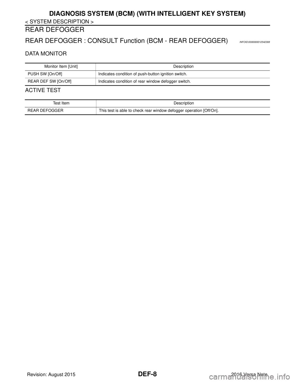
REAR DEFOGGER
REAR DEFOGGER : CONSULT Func tion (BCM - REAR DEFOGGER)INFOID:0000000012542308
DATA MONITOR
ACTIVE TEST
Monitor Item [Unit] Description
PUSH SW [On/Off] Indicates condition of push-button ignition switch.
REAR DEF SW [On/Off] Indicates condition of rear window defogger switch.
Test Item Description
REAR DEFOGGER This test is able to check rear window defogger operation [Off/On].
Revision: August 2015 2016 Versa Note
cardiagn.com
Page 703 of 3641

DLK-14
< SYSTEM DESCRIPTION >[WITH INTELLIGENT KEY SYSTEM]
COMPONENT PARTS
A. View with instrument panel assembly
removed B. View with glove box door removed C. View with front grille removed
D. View of LH door (RH similar) E. View of LH door switch (RH similar) F. View with rear bumper cover re- moved
G. View from rear of vehicle H. View with rear seat cushion removed I. View with center console removed
No. Component Function
1. Combination meter Combination meter transmits the vehicle speed sig-
nal to BCM via CAN communication.
BCM also receives the vehicle speed signal from
ABS actuator and electric uni
t (control unit) via CAN
communication. BCM compares both signals to de-
tect the vehicle speed.
Security indicator lamp is located on combination
meter.
Security indicator lamp blinks when ignition switch
is in any position other than ON to warn that NIS-
SAN VEHICLE IMMOBILIZER SYSTEM-NATS
[NVIS (NATS)] is on board.
Refer to MWI-59, "
METER SYSTEM : Combination
Meter".
2. Push-button ignition switch Push-button ignition switch has push switch inside
which detects that push-button ignition switch is
pressed, and then transmits ON/OFF signal to
BCM. BCM changes the ignition switch position with
the operation of push-button ignition switch. BCM
maintains the ignition switch position status while
push-button ignition switch is not operated.
3. BCM BCM controls INTELLIGENT KEY SYSTEM (EN-
GINE START FUNCTION), NISSAN VEHICLE IM-
MOBILIZER SYSTEM-NATS [NVIS (NATS)] and
VEHICLE SECURITY SYSTEM.
BCM performs the ID verification between BCM and
Intelligent Key when the Intelligent Key is carried
into the detection area of inside key antenna, and
push-button ignition switch is pressed. If the ID ver-
ification result is OK, ignition switch operation is
available.
Then, when the ignition switch is turned ON, BCM
performs ID verification between BCM and ECM. If
the ID verification result is OK, ECM can start en-
gine.
Refer to BCS-6, "
BODY CONTROL SYSTEM :
Component Parts Location" for detailed installation
location.
4. Main power window and door lock/unlock switch Door lock and unlock switch is integrated into the
main power window and door lock/unlock switch.
Door lock and unlock switch transmits door lock/un-
lock operation signal to BCM.
Refer to PWC-7, "
Main Power Window And Door
Lock/Unlock Switch".
5. Front door lock assembly LH Door key cylinder switch is integrated into front door
lock assembly (driver side).
Door key cylinder switch detects door LOCK/UN-
LOCK operation using mechanical key, and then
transmits the operation signal to BCM.
Refer to DLK-17, "
INTELLIGENT KEY SYSTEM :
Front Door Lock Asse
mbly (Driver Side)".
6. Rear door lock actuator LH Rear door lock actuator locks/unlocks the rear door
latch assembly.
Revision: August 2015
2016 Versa Note
cardiagn.com