engine start stop NISSAN NOTE 2016 Service Manual Online
[x] Cancel search | Manufacturer: NISSAN, Model Year: 2016, Model line: NOTE, Model: NISSAN NOTE 2016Pages: 3641, PDF Size: 28.72 MB
Page 1456 of 3641
P0461 FUEL LEVEL SENSOREC-329
< DTC/CIRCUIT DIAGNOSIS > [HR16DE]
C
D
E
F
G H
I
J
K L
M A
EC
NP
O
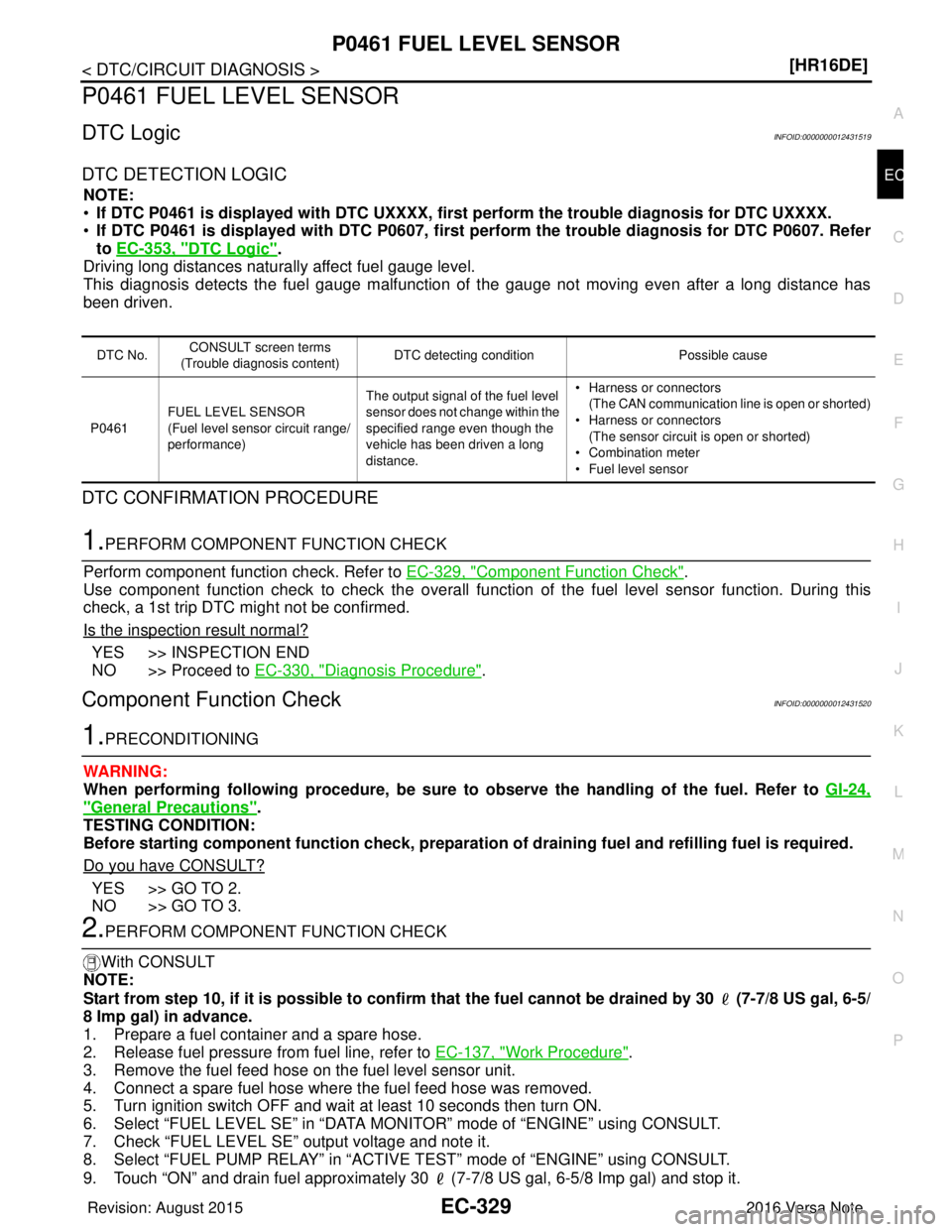
P0461 FUEL LEVEL SENSOR
DTC LogicINFOID:0000000012431519
DTC DETECTION LOGIC
NOTE:
•
If DTC P0461 is displayed with DTC UXXXX, first perform the tr ouble diagnosis for DTC UXXXX.
• If DTC P0461 is displayed with DT C P0607, first perform the trouble diagnosis for DTC P0607. Refer
to EC-353, "
DTC Logic".
Driving long distances naturally affect fuel gauge level.
This diagnosis detects the fuel gauge malfunction of the gauge not moving even after a long distance has
been driven.
DTC CONFIRMATION PROCEDURE
1.PERFORM COMPONENT FUNCTION CHECK
Perform component function check. Refer to EC-329, "
Component Function Check".
Use component function check to check the overall func tion of the fuel level sensor function. During this
check, a 1st trip DTC might not be confirmed.
Is the inspection result normal?
YES >> INSPECTION END
NO >> Proceed to EC-330, "
Diagnosis Procedure".
Component Function CheckINFOID:0000000012431520
1.PRECONDITIONING
WARNING:
When performing following procedure, be sure to observe the handling of the fuel. Refer to GI-24,
"General Precautions".
TESTING CONDITION:
Before starting component function check, preparation of draining fuel and refi lling fuel is required.
Do you have CONSULT?
YES >> GO TO 2.
NO >> GO TO 3.
2.PERFORM COMPONENT FUNCTION CHECK
With CONSULT
NOTE:
Start from step 10, if it is possible to confirm that the fuel cannot be drained by 30 (7-7/8 US gal, 6-5/
8 Imp gal) in advance.
1. Prepare a fuel container and a spare hose.
2. Release fuel pressure from fuel line, refer to EC-137, "
Work Procedure".
3. Remove the fuel feed hose on the fuel level sensor unit.
4. Connect a spare fuel hose where the fuel feed hose was removed.
5. Turn ignition switch OFF and wait at least 10 seconds then turn ON.
6. Select “FUEL LEVEL SE” in “DATA MONI TOR” mode of “ENGINE” using CONSULT.
7. Check “FUEL LEVEL SE” output voltage and note it.
8. Select “FUEL PUMP RELAY” in “ACTIV E TEST” mode of “ENGINE” using CONSULT.
9. Touch “ON” and drain fuel approximately 30 (7-7/8 US gal, 6-5/8 Imp gal) and stop it.
DTC No.CONSULT screen terms
(Trouble diagnosis content) DTC detecting condition
Possible cause
P0461 FUEL LEVEL SENSOR
(Fuel level sensor circuit range/
performance) The output signal of the fuel level
sensor does not change within the
specified range even though the
vehicle has been driven a long
distance. • Harness or connectors
(The CAN communication line is open or shorted)
• Harness or connectors (The sensor circuit is open or shorted)
• Combination meter
• Fuel level sensor
Revision: August 2015 2016 Versa Note
cardiagn.com
Page 1477 of 3641
EC-350
< DTC/CIRCUIT DIAGNOSIS >[HR16DE]
P0604 ECM
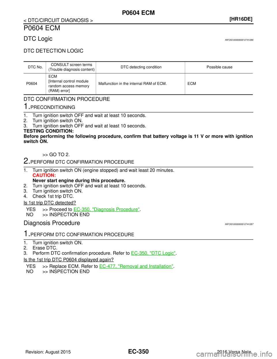
P0604 ECM
DTC LogicINFOID:0000000012741286
DTC DETECTION LOGIC
DTC CONFIRMATION PROCEDURE
1.PRECONDITIONING
1. Turn ignition switch OFF and wait at least 10 seconds.
2. Turn ignition switch ON.
3. Turn ignition switch OFF and wait at least 10 seconds.
TESTING CONDITION:
Before performing the following procedure, confirm th at battery voltage is 11 V or more with ignition
switch ON.
>> GO TO 2.
2.PERFORM DTC CONFIRMATION PROCEDURE
1. Turn ignition switch ON (engine stopped) and wait least 20 minutes. CAUTION:
Never start engine during this procedure.
2. Turn ignition switch OFF and wait at least 10 seconds.
3. Turn ignition switch ON.
4. Check 1st trip DTC.
Is 1st trip DTC detected?
YES >> Proceed to EC-350, "Diagnosis Procedure".
NO >> INSPECTION END
Diagnosis ProcedureINFOID:0000000012741287
1.PERFORM DTC CONFIRMATION PROCEDURE
1. Turn ignition switch ON.
2. Erase DTC.
3. Perform DTC confirmation procedure. Refer to EC-350, "
DTC Logic".
Is the 1st trip DTC
P0604 displayed again?
YES >> Replace ECM. Refer to EC-477, "Removal and Installation".
NO >> INSPECTION END
DTC No. CONSULT screen terms
(Trouble diagnosis content) DTC detecting condition
Possible cause
P0604 ECM
[Internal control module
random access memory
(RAM) error] Malfunction in the internal RAM of ECM.
ECM
Revision: August 2015 2016 Versa Note
cardiagn.com
Page 1478 of 3641
P0605 ECMEC-351
< DTC/CIRCUIT DIAGNOSIS > [HR16DE]
C
D
E
F
G H
I
J
K L
M A
EC
NP
O
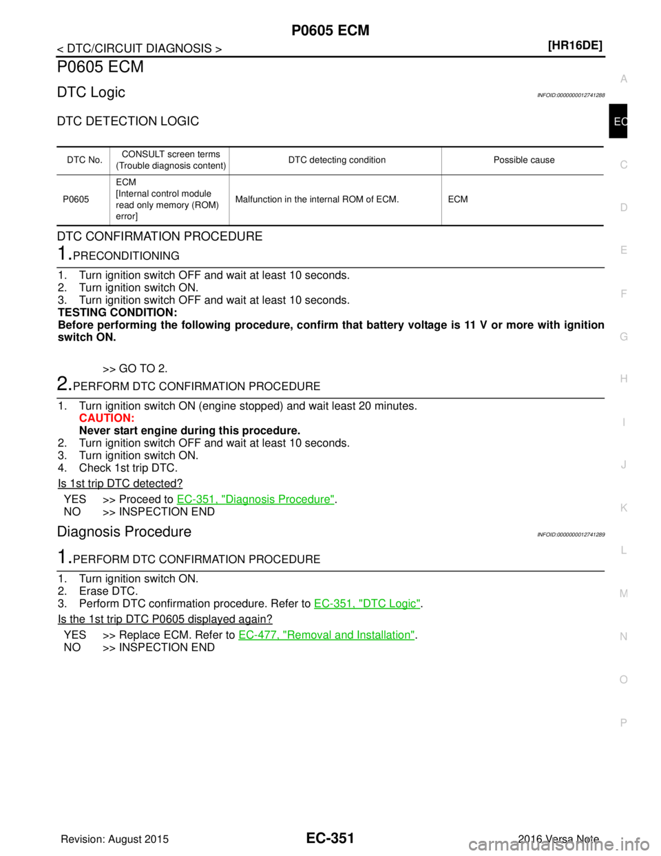
P0605 ECM
DTC LogicINFOID:0000000012741288
DTC DETECTION LOGIC
DTC CONFIRMATION PROCEDURE
1.PRECONDITIONING
1. Turn ignition switch OFF and wait at least 10 seconds.
2. Turn ignition switch ON.
3. Turn ignition switch OFF and wait at least 10 seconds.
TESTING CONDITION:
Before performing the following procedure, confirm that battery voltag e is 11 V or more with ignition
switch ON.
>> GO TO 2.
2.PERFORM DTC CONFIRMATION PROCEDURE
1. Turn ignition switch ON (engine stopped) and wait least 20 minutes. CAUTION:
Never start engine during this procedure.
2. Turn ignition switch OFF and wait at least 10 seconds.
3. Turn ignition switch ON.
4. Check 1st trip DTC.
Is 1st trip DTC detected?
YES >> Proceed to EC-351, "Diagnosis Procedure".
NO >> INSPECTION END
Diagnosis ProcedureINFOID:0000000012741289
1.PERFORM DTC CONFIRMATION PROCEDURE
1. Turn ignition switch ON.
2. Erase DTC.
3. Perform DTC confirmation procedure. Refer to EC-351, "
DTC Logic".
Is the 1st trip DTC
P0605 displayed again?
YES >> Replace ECM. Refer to EC-477, "Removal and Installation".
NO >> INSPECTION END
DTC No. CONSULT screen terms
(Trouble diagnosis content) DTC detecting condition
Possible cause
P0605 ECM
[Internal control module
read only me
mory (ROM)
error] Malfunction in the internal ROM of ECM.
ECM
Revision: August 2015 2016 Versa Note
cardiagn.com
Page 1479 of 3641
EC-352
< DTC/CIRCUIT DIAGNOSIS >[HR16DE]
P0606 ECM
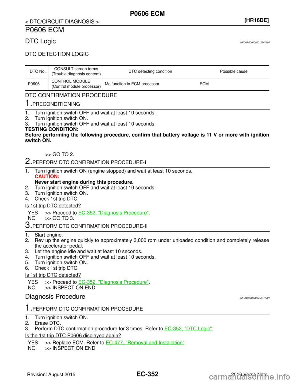
P0606 ECM
DTC LogicINFOID:0000000012741290
DTC DETECTION LOGIC
DTC CONFIRMATION PROCEDURE
1.PRECONDITIONING
1. Turn ignition switch OFF and wait at least 10 seconds.
2. Turn ignition switch ON.
3. Turn ignition switch OFF and wait at least 10 seconds.
TESTING CONDITION:
Before performing the following procedure, confirm th at battery voltage is 11 V or more with ignition
switch ON.
>> GO TO 2.
2.PERFORM DTC CONFIRMATION PROCEDURE-I
1. Turn ignition switch ON (engine stopped) and wait at least 10 seconds. CAUTION:
Never start engine during this procedure.
2. Turn ignition switch OFF and wait at least 10 seconds.
3. Turn ignition switch ON.
4. Check 1st trip DTC.
Is 1st trip DTC detected?
YES >> Proceed to EC-352, "Diagnosis Procedure".
NO >> GO TO 3.
3.PERFORM DTC CONFIRMATION PROCEDURE-II
1. Start engine.
2. Rev up the engine quickly to approximately 3,000 rpm under unloaded condition and completely release the accelerator pedal.
3. Let the engine idle and wait at least 10 seconds.
4. Turn ignition switch OFF and wait at least 10 seconds.
5. Turn ignition switch ON.
6. Check 1st trip DTC.
Is 1st trip DTC detected?
YES >> Proceed to EC-352, "Diagnosis Procedure".
NO >> INSPECTION END
Diagnosis ProcedureINFOID:0000000012741291
1.PERFORM DTC CONFIRMATION PROCEDURE
1. Turn ignition switch ON.
2. Erase DTC.
3. Perform DTC confirmation procedure for 3 times. Refer to EC-352, "
DTC Logic".
Is the 1st trip DTC
P0606 displayed again?
YES >> Replace ECM. Refer to EC-477, "Removal and Installation".
NO >> INSPECTION END
DTC No. CONSULT screen terms
(Trouble diagnosis content) DTC detecting condition
Possible cause
P0606 CONTROL MODULE
(Control module processor) Malfunction in ECM processor.
ECM
Revision: August 2015 2016 Versa Note
cardiagn.com
Page 1510 of 3641
P1572 ASCD BRAKE SWITCHEC-383
< DTC/CIRCUIT DIAGNOSIS > [HR16DE]
C
D
E
F
G H
I
J
K L
M A
EC
NP
O
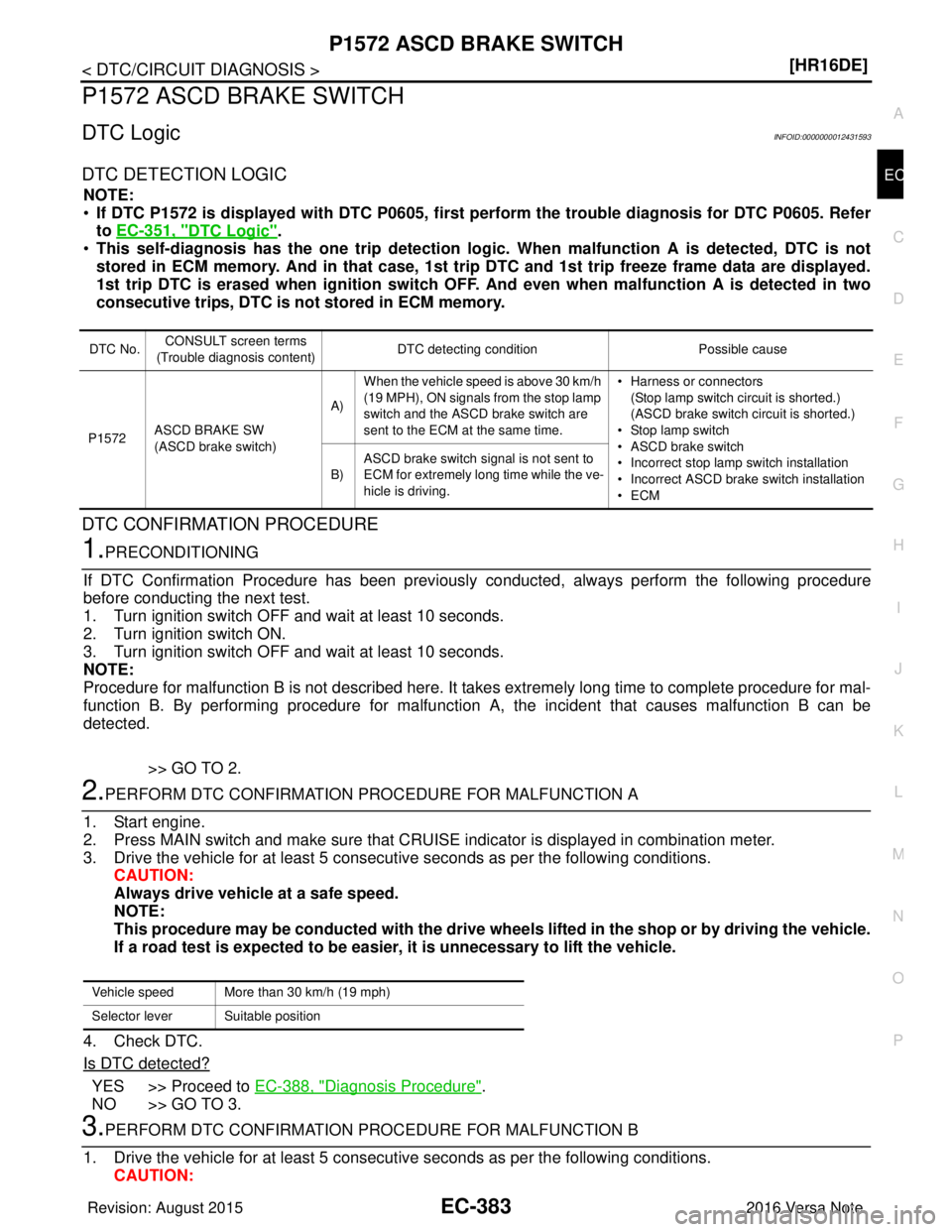
P1572 ASCD BRAKE SWITCH
DTC LogicINFOID:0000000012431593
DTC DETECTION LOGIC
NOTE:
•
If DTC P1572 is displayed with DT C P0605, first perform the trouble diagnosis for DTC P0605. Refer
to EC-351, "
DTC Logic".
• This self-diagnosis has the one trip detection logic. When malfunction A is detected, DTC is not
stored in ECM memory. And in that case, 1st trip DTC and 1st trip freeze frame data are displayed.
1st trip DTC is erased when ignition switch OFF. And even when ma lfunction A is detected in two
consecutive trips, DTC is not stored in ECM memory.
DTC CONFIRMATION PROCEDURE
1.PRECONDITIONING
If DTC Confirmation Procedure has been previously conducted, always perform the following procedure
before conducting the next test.
1. Turn ignition switch OFF and wait at least 10 seconds.
2. Turn ignition switch ON.
3. Turn ignition switch OFF and wait at least 10 seconds.
NOTE:
Procedure for malfunction B is not described here. It take s extremely long time to complete procedure for mal-
function B. By performing procedure for malfunction A, the incident that causes malfunction B can be
detected.
>> GO TO 2.
2.PERFORM DTC CONFIRMATION PROCEDURE FOR MALFUNCTION A
1. Start engine.
2. Press MAIN switch and make sure that CRUISE indicator is displayed in combination meter.
3. Drive the vehicle for at least 5 consecut ive seconds as per the following conditions.
CAUTION:
Always drive vehicle at a safe speed.
NOTE:
This procedure may be conducted with the drive wheel s lifted in the shop or by driving the vehicle.
If a road test is expected to be easier , it is unnecessary to lift the vehicle.
4. Check DTC.
Is DTC detected?
YES >> Proceed to EC-388, "Diagnosis Procedure".
NO >> GO TO 3.
3.PERFORM DTC CONFIRMATION PROCEDURE FOR MALFUNCTION B
1. Drive the vehicle for at least 5 consecut ive seconds as per the following conditions.
CAUTION:
DTC No. CONSULT screen terms
(Trouble diagnosis content) DTC detecting condition
Possible cause
P1572 ASCD BRAKE SW
(ASCD brake switch) A)
When the vehicle speed is above 30 km/h
(19 MPH), ON signals from the stop lamp
switch and the ASCD brake switch are
sent to the ECM at the same time. • Harness or connectors
(Stop lamp switch circuit is shorted.)
(ASCD brake switch circuit is shorted.)
• Stop lamp switch
• ASCD brake switch
• Incorrect stop lamp switch installation
• Incorrect ASCD brake switch installation
•ECM
B)
ASCD brake switch signal is not sent to
ECM for extremely long time while the ve-
hicle is driving.
Vehicle speed More than 30 km/h (19 mph)
Selector lever Suitable position
Revision: August 2015
2016 Versa Note
cardiagn.com
Page 1517 of 3641
EC-390
< DTC/CIRCUIT DIAGNOSIS >[HR16DE]
P159F ACTIVE GRILLE SHUTTER
P159F ACTIVE GRILLE SHUTTER
DTC LogicINFOID:0000000012431600
DTC DETECTION LOGIC
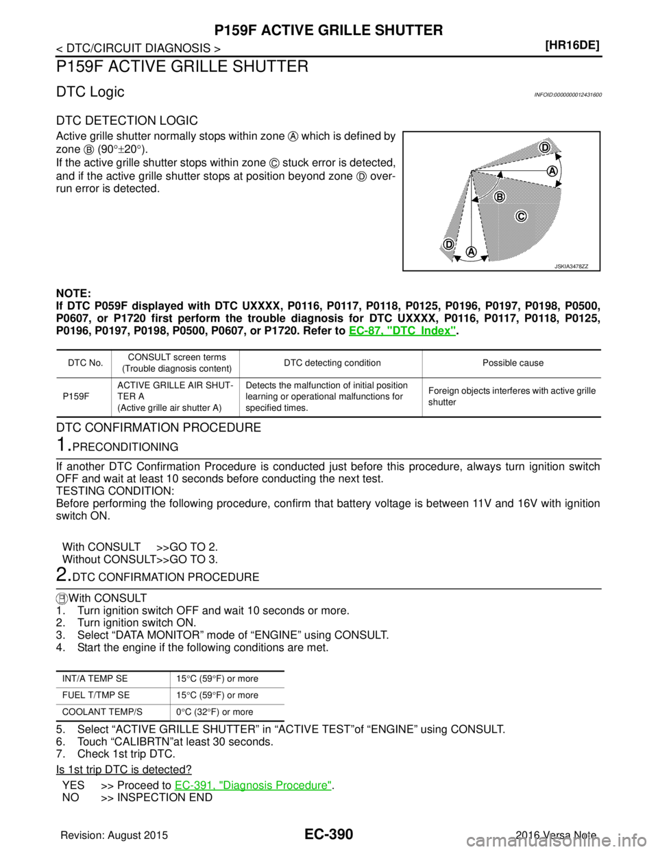
Active grille shutter normally stops within zone which is defined by
zone (90
°±20° ).
If the active grille shutter stops within zone stuck error is detected,
and if the active grille shutter stops at position beyond zone over-
run error is detected.
NOTE:
If DTC P059F displayed with DTC UXXXX, P0116, P0117, P0118, P0125, P0196, P0197, P0198, P0500,
P0607, or P1720 first perform the trouble diagnosis for DTC UXXXX, P0116, P0117, P0118, P0125,
P0196, P0197, P0198, P0500, P0607, or P1720. Refer to EC-87, "
DTCIndex".
DTC CONFIRMATION PROCEDURE
1.PRECONDITIONING
If another DTC Confirmation Procedure is conducted just before this procedure, always turn ignition switch
OFF and wait at least 10 seconds before conducting the next test.
TESTING CONDITION:
Before performing the following procedure, confirm that battery voltage is between 11V and 16V with ignition
switch ON.
With CONSULT >>GO TO 2.
Without CONSULT>>GO TO 3.
2.DTC CONFIRMATION PROCEDURE
With CONSULT
1. Turn ignition switch OFF and wait 10 seconds or more.
2. Turn ignition switch ON.
3. Select “DATA MONITOR” mode of “ENGINE” using CONSULT.
4. Start the engine if the following conditions are met.
5. Select “ACTIVE GRILLE SHUTTER” in “ACTIVE TEST”of “ENGINE” using CONSULT.
6. Touch “CALIBRTN”at least 30 seconds.
7. Check 1st trip DTC.
Is 1st trip DTC is detected?
YES >> Proceed to EC-391, "Diagnosis Procedure".
NO >> INSPECTION END
JSKIA3478ZZ
DTC No. CONSULT screen terms
(Trouble diagnosis content) DTC detecting condition
Possible cause
P159F ACTIVE GRILLE AIR SHUT-
TER A
(Active grille air shutter A) Detects the malfunction of initial position
learning or operational malfunctions for
specified times.
Foreign objects interferes with active grille
shutter
INT/A TEMP SE
15°C (59 °F) or more
FUEL T/TMP SE 15°C (59 °F) or more
COOLANT TEMP/S 0 °C (32 °F) or more
Revision: August 2015 2016 Versa Note
cardiagn.com
Page 1554 of 3641
P219A AIR FUEL RATIOEC-427
< DTC/CIRCUIT DIAGNOSIS > [HR16DE]
C
D
E
F
G H
I
J
K L
M A
EC
NP
O
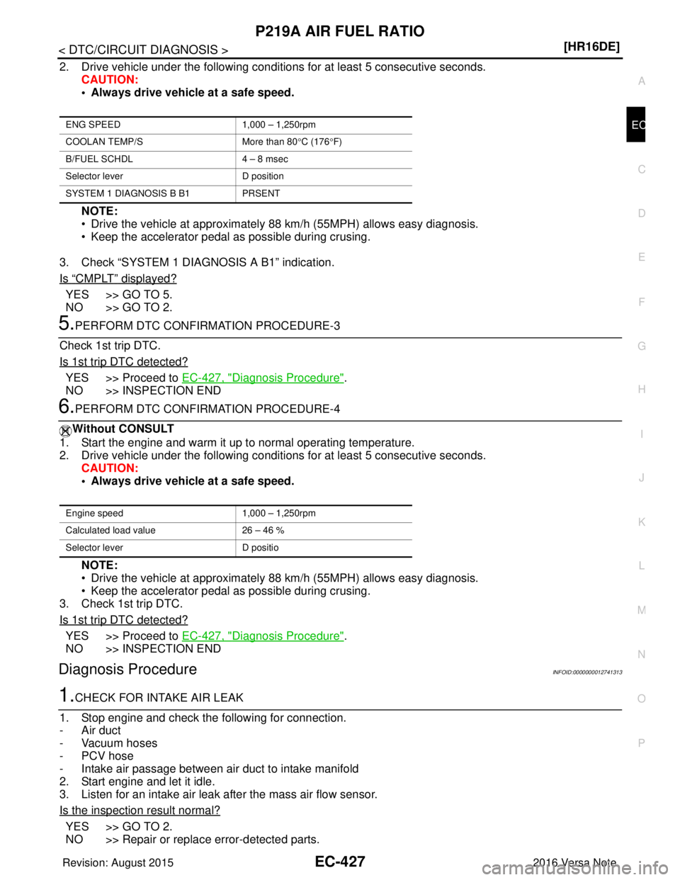
2. Drive vehicle under the following conditions for at least 5 consecutive seconds.
CAUTION:
• Always drive vehicle at a safe speed.
NOTE:
• Drive the vehicle at approximately 88 km/h (55MPH) allows easy diagnosis.
• Keep the accelerator pedal as possible during crusing.
3. Check “SYSTEM 1 DIAGNOSIS A B1” indication.
Is
“CMPLT” displayed?
YES >> GO TO 5.
NO >> GO TO 2.
5.PERFORM DTC CONFIRMATION PROCEDURE-3
Check 1st trip DTC.
Is 1st trip DTC detected?
YES >> Proceed to EC-427, "Diagnosis Procedure".
NO >> INSPECTION END
6.PERFORM DTC CONFIRMATION PROCEDURE-4
Without CONSULT
1. Start the engine and warm it up to normal operating temperature.
2. Drive vehicle under the following conditions for at least 5 consecutive seconds. CAUTION:
• Always drive vehicle at a safe speed.
NOTE:
• Drive the vehicle at approximately 88 km/h (55MPH) allows easy diagnosis.
• Keep the accelerator pedal as possible during crusing.
3. Check 1st trip DTC.
Is 1st trip DTC detected?
YES >> Proceed to EC-427, "Diagnosis Procedure".
NO >> INSPECTION END
Diagnosis ProcedureINFOID:0000000012741313
1.CHECK FOR INTAKE AIR LEAK
1. Stop engine and check the following for connection.
- Air duct
- Vacuum hoses
- PCV hose
- Intake air passage between air duct to intake manifold
2. Start engine and let it idle.
3. Listen for an intake air leak after the mass air flow sensor.
Is the inspection result normal?
YES >> GO TO 2.
NO >> Repair or replace error-detected parts.
ENG SPEED 1,000 – 1,250rpm
COOLAN TEMP/S More than 80°C (176 °F)
B/FUEL SCHDL 4 – 8 msec
Selector lever D position
SYSTEM 1 DIAGNOSIS B B1 PRSENT
Engine speed1,000 – 1,250rpm
Calculated load value 26 – 46 %
Selector lever D positio
Revision: August 2015 2016 Versa Note
cardiagn.com
Page 1555 of 3641
EC-428
< DTC/CIRCUIT DIAGNOSIS >[HR16DE]
P219A AIR FUEL RATIO
2.CHECK EXHAUST GAS LEAK
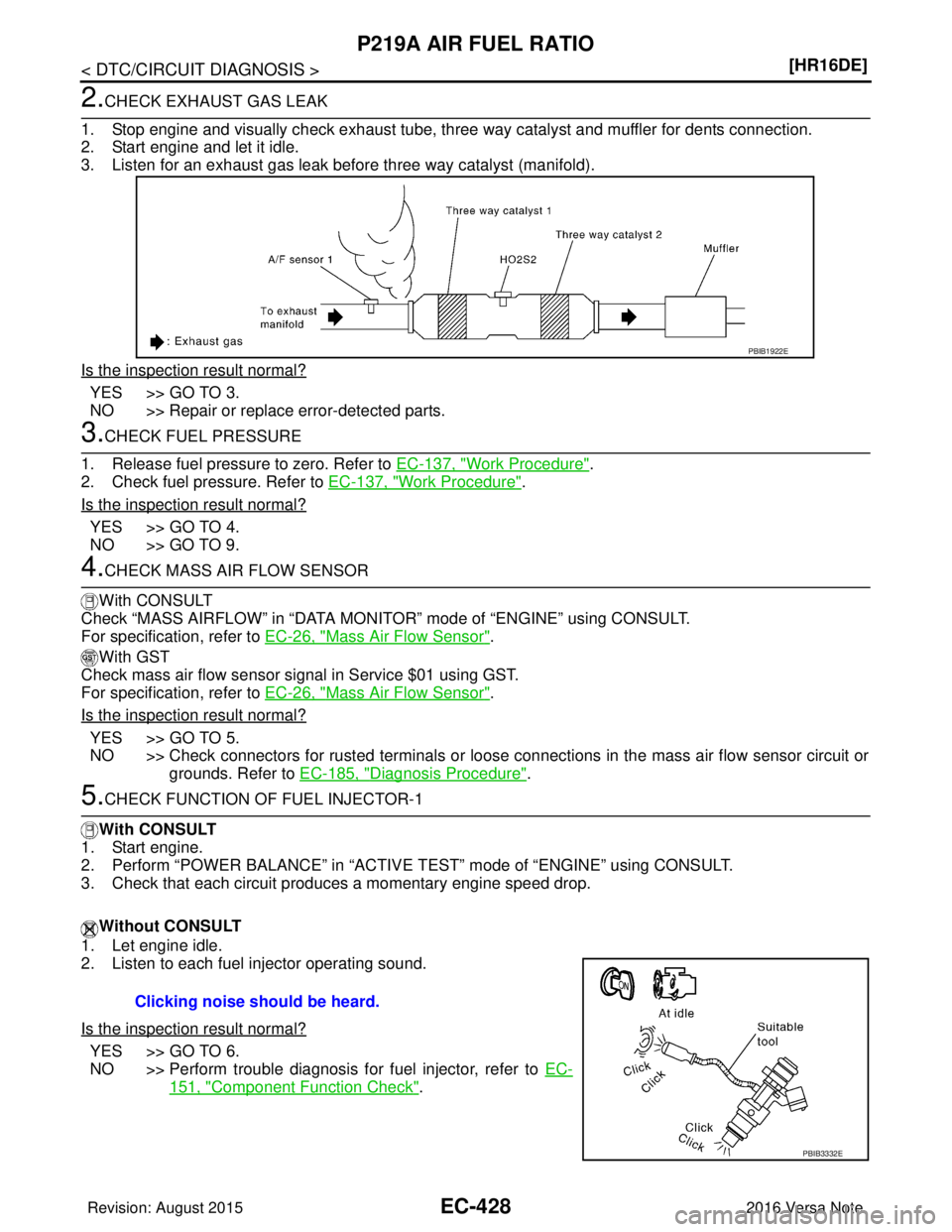
1. Stop engine and visually check exhaust tube, three way catalyst and muffler for dents connection.
2. Start engine and let it idle.
3. Listen for an exhaust gas leak before three way catalyst (manifold).
Is the inspection result normal?
YES >> GO TO 3.
NO >> Repair or replace error-detected parts.
3.CHECK FUEL PRESSURE
1. Release fuel pressure to zero. Refer to EC-137, "
Work Procedure".
2. Check fuel pressure. Refer to EC-137, "
Work Procedure".
Is the inspection result normal?
YES >> GO TO 4.
NO >> GO TO 9.
4.CHECK MASS AIR FLOW SENSOR
With CONSULT
Check “MASS AIRFLOW” in “DATA MONITOR” mode of “ENGINE” using CONSULT.
For specification, refer to EC-26, "
Mass Air Flow Sensor".
With GST
Check mass air flow sensor signal in Service $01 using GST.
For specification, refer to EC-26, "
Mass Air Flow Sensor".
Is the inspection result normal?
YES >> GO TO 5.
NO >> Check connectors for rusted terminals or loose connections in the mass air flow sensor circuit or grounds. Refer to EC-185, "
Diagnosis Procedure".
5.CHECK FUNCTION OF FUEL INJECTOR-1
With CONSULT
1. Start engine.
2. Perform “POWER BALANCE” in “ACTIVE TEST” mode of “ENGINE” using CONSULT.
3. Check that each circuit produces a momentary engine speed drop.
Without CONSULT
1. Let engine idle.
2. Listen to each fuel injector operating sound.
Is the inspection result normal?
YES >> GO TO 6.
NO >> Perform trouble diagnosis for fuel injector, refer to EC-
151, "Component Function Check".
PBIB1922E
Clicking noise should be heard.
PBIB3332E
Revision: August 2015 2016 Versa Note
cardiagn.com
Page 1560 of 3641

P219C, P219D, P219E, P219F AIR FUEL RATIO
EC-433
< DTC/CIRCUIT DIAGNOSIS > [HR16DE]
C
D
E
F
G H
I
J
K L
M A
EC
NP
O
Diagnosis ProcedureINFOID:0000000012741315
1.CHECK FOR INTAKE AIR LEAK
1. Stop engine and check the following for connection.
- Air duct
- Vacuum hoses
- PCV hose
- Intake air passage between air duct to intake manifold
2. Start engine and let it idle.
3. Listen for an intake air leak after the mass air flow sensor.
Is the inspection result normal?
YES >> GO TO 2.
NO >> Repair or replace error-detected parts.
2.CHECK EXHAUST GAS LEAK
1. Stop engine and visually check exhaust tube, three way catalyst and muffler for dents connection.
2. Start engine and let it idle.
3. Listen for an exhaust gas leak before three way catalyst (manifold).
Is the inspection result normal?
YES >> GO TO 3.
NO >> Repair or replace error-detected parts.
3.CHECK FUEL PRESSURE
1. Release fuel pressure to zero. Refer to EC-137, "
Work Procedure".
2. Check fuel pressure. Refer to EC-137, "
Work Procedure".
Is the inspection result normal?
YES >> GO TO 4.
NO >> GO TO 9.
4.CHECK MASS AIR FLOW SENSOR
With CONSULT
Check “MASS AIRFLOW” in “DATA MONITO R” mode of “ENGINE” using CONSULT.
For specification, refer to EC-26, "
Mass Air Flow Sensor".
With GST
Check mass air flow sensor signal in Service $01 using GST.
For specification, refer to EC-26, "
Mass Air Flow Sensor".
Is the inspection result normal?
YES >> GO TO 5.
NO >> Check connectors for rusted terminals or loose connections in the mass air flow sensor circuit or grounds. Refer to EC-185, "
Diagnosis Procedure".
5.CHECK FUNCTION OF FUEL INJECTOR-1
With CONSULT
1. Start engine.
2. Perform “POWER BALANCE” in “ACTIVE TEST” mode of “ENGINE” using CONSULT.
3. Check that each circuit produces a momentary engine speed drop.
PBIB1922E
Revision: August 2015 2016 Versa Note
cardiagn.com
Page 1589 of 3641

EC-462
< DTC/CIRCUIT DIAGNOSIS >[HR16DE]
REFRIGERANT PRESSURE SENSOR
REFRIGERANT PRESSURE SENSOR
Component Function CheckINFOID:0000000012431664
1.CHECK REFRIGERANT PRESSURE SENSOR OVERALL FUNCTION
1. Start engine and warm it up to normal operating temperature.
2. Turn A/C switch and blower fan switch ON.
3. Check the voltage between ECM harness connector and ground.
Is the inspection result normal?
YES >> INSPECTION END
NO >> Go to EC-462, "
Diagnosis Procedure".
Diagnosis ProcedureINFOID:0000000012431665
1.CHECK GROUND CONNECTION
1. Turn A/C switch and blower fan switch OFF.
2. Stop engine.
3. Turn ignition switch OFF.
4. Check ground connection E15. Refer to Ground Inspection in GI-44, "
Circuit Inspection".
Is the inspection result normal?
YES >> GO TO 2.
NO >> Repair or replace ground connection.
2.CHECK REFRIGERANT PRESSURE SENSOR POWER SUPPLY CIRCUIT
1. Disconnect refrigerant pressure sensor harness connector.
2. Turn ignition switch ON.
3. Check the voltage between refrigerant pressure sensor harness connector and ground.
Is the inspection result normal?
YES >> GO TO 4.
NO >> GO TO 3.
3.DETECT MALFUNCTIONING PART
Check the following.
• Harness for open or short between ECM and refrigerant pressure sensor
>> Repair open circuit or short to ground or short to power in harness or connectors.
4.CHECK REFRIGERANT PRESSURE SENSOR GROUND CIRCUIT FOR OPEN AND SHORT
1. Turn ignition switch OFF.
2. Disconnect ECM harness connector.
3. Check the continuity between refrigerant pre ssure sensor harness connector and ECM harness connec-
tor.
ECM
Vol tag e
Connector Te r m i n a l
+ −
E16 101
(Refrigerant pressure sensor signal) 98 1.0 - 4.0V
Refrigerant pressure sensor
Ground Voltage
Connector Terminal
E17 3Ground Approx. 5 V
Revision: August 2015 2016 Versa Note
cardiagn.com