engine start stop NISSAN NOTE 2016 Service Manual PDF
[x] Cancel search | Manufacturer: NISSAN, Model Year: 2016, Model line: NOTE, Model: NISSAN NOTE 2016Pages: 3641, PDF Size: 28.72 MB
Page 1258 of 3641
IDLE AIR VOLUME LEARNINGEC-131
< BASIC INSPECTION > [HR16DE]
C
D
E
F
G H
I
J
K L
M A
EC
NP
O
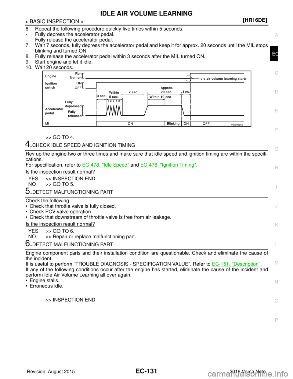
6. Repeat the following procedure quick
ly five times within 5 seconds.
- Fully depress the accelerator pedal.
- Fully release the accelerator pedal.
7. Wait 7 seconds, fully depress the accelerator pedal and keep it for approx. 20 seconds until the MIL stops blinking and turned ON.
8. Fully release the accelerator pedal within 3 seconds after the MIL turned ON.
9. Start engine and let it idle.
10. Wait 20 seconds.
>> GO TO 4.
4.CHECK IDLE SPEED AND IGNITION TIMING
Rev up the engine two or three times and make sure that idle speed and ignition timing are within the specifi-
cations.
For specification, refer to EC-478, "
Idle Speed" and EC-478, "Ignition Timing".
Is the inspection result normal?
YES >> INSPECTION END
NO >> GO TO 5.
5.DETECT MALFUNCTIONING PART
Check the following
• Check that throttle valve is fully closed.
• Check PCV valve operation.
• Check that downstream of throttle valve is free from air leakage.
Is the inspection result normal?
YES >> GO TO 6.
NO >> Repair or replace malfunctioning part.
6.DETECT MALFUNCTIONING PART
Engine component parts and their installation conditi on are questionable. Check and eliminate the cause of
the incident.
It is useful to perform “TROUBLE DIAG NOSIS - SPECIFICATION VALUE”. Refer to EC-151, "
Description".
If any of the following conditions occur after the engi ne has started, eliminate the cause of the incident and
perform Idle Air Volume Learning all over again:
• Engine stalls.
• Erroneous idle.
>> INSPECTION END
PBIB0665E
Revision: August 2015 2016 Versa Note
cardiagn.com
Page 1259 of 3641
EC-132
< BASIC INSPECTION >[HR16DE]
MIXTURE RATIO SELF-LEARNING VALUE CLEAR
MIXTURE RATIO SELF-LEARNING VALUE CLEAR
DescriptionINFOID:0000000012431360
This describes how to erase the mixture ratio self-learni
ng value. For the actual procedure, follow the instruc-
tions in “Diagnosis Procedure”. Refer to EC-132, "
Work Procedure".
Work ProcedureINFOID:0000000012431361
1.START
With CONSULT
1. Start engine and warm it up to normal operating temperature.
2. Select “SELF-LEARNING CONT” in “WORK SUPPORT” mode with CONSULT.
3. Clear mixture ratio self-lear ning value by touching “CLEAR”.
With GST
1. Start engine and warm it up to normal operating temperature.
2. Turn ignition switch OFF.
3. Disconnect mass air flow sensor harness connector.
4. Restart engine and let it idle for at least 5 seconds.
5. Stop engine and reconnect mass air flow sensor harness connector.
6. Select Service $03 with GST. Make sure DTC P0102 is detected.
7. Select Service $04 with GST to erase the DTC P0102.
>> END
Revision: August 2015 2016 Versa Note
cardiagn.com
Page 1261 of 3641
EC-134
< BASIC INSPECTION >[HR16DE]
BASIC INSPECTION
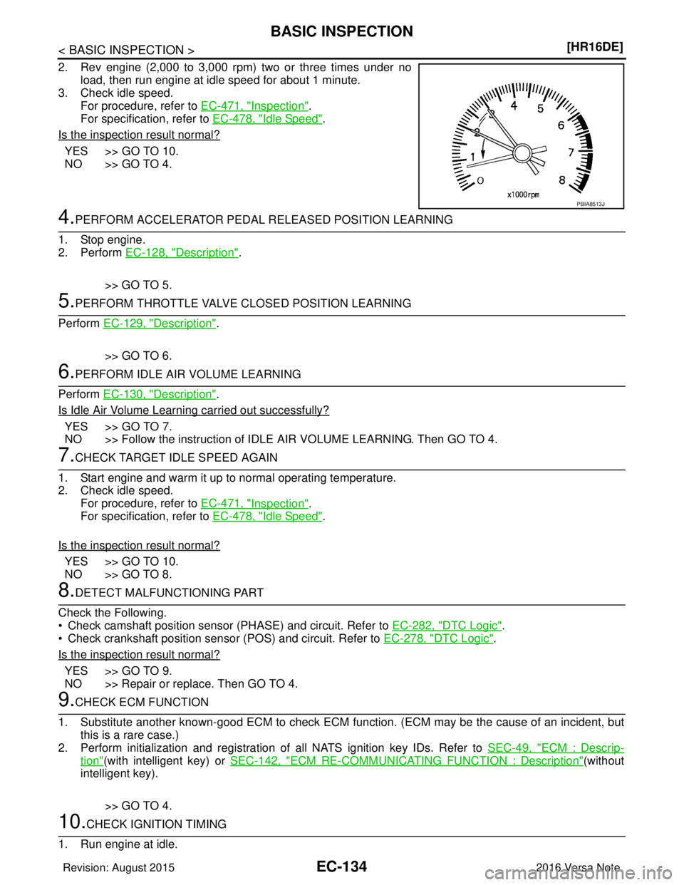
2. Rev engine (2,000 to 3,000 rpm) two or three times under no
load, then run engine at idle speed for about 1 minute.
3. Check idle speed.
For procedure, refer to EC-471, "
Inspection".
For specification, refer to EC-478, "
Idle Speed".
Is the inspection result normal?
YES >> GO TO 10.
NO >> GO TO 4.
4.PERFORM ACCELERATOR PEDAL RE LEASED POSITION LEARNING
1. Stop engine.
2. Perform EC-128, "
Description".
>> GO TO 5.
5.PERFORM THROTTLE VALVE CL OSED POSITION LEARNING
Perform EC-129, "
Description".
>> GO TO 6.
6.PERFORM IDLE AIR VOLUME LEARNING
Perform EC-130, "
Description".
Is Idle Air Volume Learning carried out successfully?
YES >> GO TO 7.
NO >> Follow the instruction of IDLE AIR VOLUME LEARNING. Then GO TO 4.
7.CHECK TARGET IDLE SPEED AGAIN
1. Start engine and warm it up to normal operating temperature.
2. Check idle speed. For procedure, refer to EC-471, "
Inspection".
For specification, refer to EC-478, "
Idle Speed".
Is the inspection result normal?
YES >> GO TO 10.
NO >> GO TO 8.
8.DETECT MALFUNCTIONING PART
Check the Following.
• Check camshaft position sensor (PHASE) and circuit. Refer to EC-282, "
DTC Logic".
• Check crankshaft position sensor (POS) and circuit. Refer to EC-278, "
DTC Logic".
Is the inspection result normal?
YES >> GO TO 9.
NO >> Repair or replace. Then GO TO 4.
9.CHECK ECM FUNCTION
1. Substitute another known-good ECM to check ECM function. (ECM may be the cause of an incident, but this is a rare case.)
2. Perform initialization and registration of all NATS ignition key IDs. Refer to SEC-49, "
ECM : Descrip-
tion"(with intelligent key) or SEC-142, "ECM RE-COMMUNICATING FUNCTION : Description"(without
intelligent key).
>> GO TO 4.
10.CHECK IGNITION TIMING
1. Run engine at idle.
PBIA8513J
Revision: August 2015 2016 Versa Note
cardiagn.com
Page 1262 of 3641
BASIC INSPECTIONEC-135
< BASIC INSPECTION > [HR16DE]
C
D
E
F
G H
I
J
K L
M A
EC
NP
O
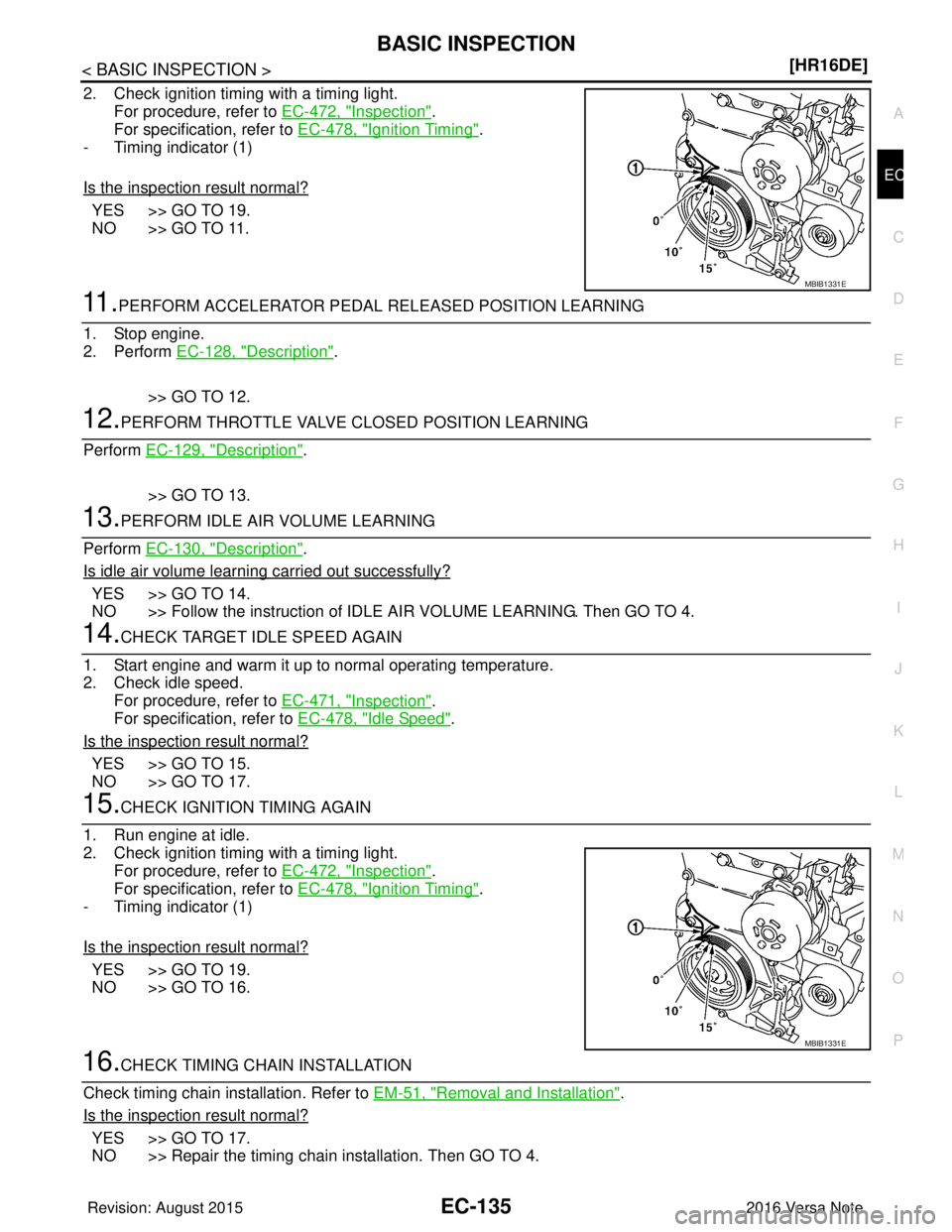
2. Check ignition timing with a timing light.
For procedure, refer to EC-472, "
Inspection".
For specification, refer to EC-478, "
Ignition Timing".
- Timing indicator (1)
Is the inspection result normal?
YES >> GO TO 19.
NO >> GO TO 11.
11 .PERFORM ACCELERATOR PEDAL RELEASED POSITION LEARNING
1. Stop engine.
2. Perform EC-128, "
Description".
>> GO TO 12.
12.PERFORM THROTTLE VALVE CLOSED POSITION LEARNING
Perform EC-129, "
Description".
>> GO TO 13.
13.PERFORM IDLE AIR VOLUME LEARNING
Perform EC-130, "
Description".
Is idle air volume learning carried out successfully?
YES >> GO TO 14.
NO >> Follow the instruction of IDLE AIR VOLUME LEARNING. Then GO TO 4.
14.CHECK TARGET IDLE SPEED AGAIN
1. Start engine and warm it up to normal operating temperature.
2. Check idle speed. For procedure, refer to EC-471, "
Inspection".
For specification, refer to EC-478, "
Idle Speed".
Is the inspection result normal?
YES >> GO TO 15.
NO >> GO TO 17.
15.CHECK IGNITION TIMING AGAIN
1. Run engine at idle.
2. Check ignition timing with a timing light. For procedure, refer to EC-472, "
Inspection".
For specification, refer to EC-478, "
Ignition Timing".
- Timing indicator (1)
Is the inspection result normal?
YES >> GO TO 19.
NO >> GO TO 16.
16.CHECK TIMING CHAIN INSTALLATION
Check timing chain installation. Refer to EM-51, "
Removal and Installation".
Is the inspection result normal?
YES >> GO TO 17.
NO >> Repair the timing chain installation. Then GO TO 4.
MBIB1331E
MBIB1331E
Revision: August 2015 2016 Versa Note
cardiagn.com
Page 1270 of 3641
HOW TO SET SRT CODEEC-143
< BASIC INSPECTION > [HR16DE]
C
D
E
F
G H
I
J
K L
M A
EC
NP
O
• Fuel tank temperature: Less than 4.1 V
Refer to
EC-71, "
Reference Value".
>> GO TO 6.
6.PATTERN 2
1. Drive the vehicle. And depress the accelerator pedal until vehicle speed is 90 km/h (56 MPH), then
release the accelerator pedal and keep it released for more than 10 seconds.
2. Depress the accelerator pedal until vehicle speed is 90 km/h (56 MPH) again
NOTE:
• Checking the vehicle speed with GST is advised.
• When steady-state driving is performed again even afte r it is interrupted, each diagnosis can be conducted.
In this case, the time required for diagnosis may be extended.
>> GO TO 7.
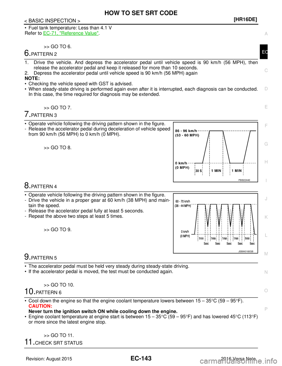
7.PATTERN 3
• Operate vehicle following the driving pattern shown in the figure.
- Release the accelerator pedal during deceleration of vehicle speed from 90 km/h (56 MPH) to 0 km/h (0 MPH).
>> GO TO 8.
8.PATTERN 4
• Operate vehicle following the driving pattern shown in the figure.
- Drive the vehicle in a proper gear at 60 km/h (38 MPH) and main- tain the speed.
- Release the accelerator pedal fully at least 5 seconds.
- Repeat the above two steps at least 5 times.
>> GO TO 9.
9.PATTERN 5
• The accelerator pedal must be held very steady during steady-state driving.
• If the accelerator pedal is moved, the test must be conducted again.
>> GO TO 10.
10.PATTERN 6
• Cool down the engine so that the engine c oolant temperature lowers between 15 – 35°C (59 – 95 °F).
CAUTION:
Never turn the ignition switch ON while cooling down the engine.
• Engine coolant temperature at engine start is between 15 – 35 °C (59 – 95 °F) and has lowered 45 °C (113 °F)
or more since the latest engine stop.
>> GO TO 11.
11 .CHECK SRT STATUS
PBIB2244E
JSBIA0160GB
Revision: August 2015 2016 Versa Note
cardiagn.com
Page 1281 of 3641
EC-154
< DTC/CIRCUIT DIAGNOSIS >[HR16DE]
TROUBLE DIAGNOSIS - SPECIFICATION VALUE
NOTE:
Check “A/F ALPHA-B1” for approximately 1 minute because
it may fluctuate. It is NG if the indication is
out of the SP value even a little.
Is the measurement value within the SP value?
YES >> GO TO 17.
NO-1 >> Less than the SP value: GO TO 2.
NO-2 >> More than the SP value: GO TO 3.
2.CHECK “B/FUEL SCHDL”
Select “B/FUEL SCHDL” in “SPEC” of “DATA MONITOR” mode, and make sure that the indication is within the
SP value.
Is the measurement value within the SP value?
YES >> GO TO 4.
NO >> More than the SP value: GO TO 19.
3.CHECK “B/FUEL SCHDL”
Select “B/FUEL SCHDL” in “SPEC” of “DATA MONITOR” mode, and make sure that the indication is within the
SP value.
Is the measurement value within the SP value?
YES >> GO TO 6.
NO-1 >> More than the SP value: GO TO 6.
NO-2 >> Less than the SP value: GO TO 25.
4.CHECK “A/F ALPHA-B1”
1. Stop the engine.
2. Disconnect PCV hose, and then plug it.
3. Start engine.
4. Select “A/F ALPHA-B1” in “SPEC” of “DATA MONITO R” mode, and make sure that the indication is within
the SP value.
Is the measurement value within the SP value?
YES >> GO TO 5.
NO >> GO TO 6.
5.CHANGE ENGINE OIL
1. Stop the engine.
2. Change engine oil. NOTE:
This symptom may occur when a large amount of gasoline is mixed with engine oil because of driving
conditions (such as when engine oil temperature does not rise enough since a journey distance is too
short during winter). The symptom will not be detected after changing engine oil or changing driving con-
dition.
>>INSPECTION END
6.CHECK FUEL PRESSURE
Check fuel pressure. (Refer to EC-137, "
Work Procedure".)
Is the inspection result normal?
YES >> GO TO 9.
NO-1 >> Fuel pressure is too high: Replace f uel filter and fuel pump assembly (Refer to FL-6, "
Exploded
View"), and then GO TO 8.
NO-2 >> Fuel pressure is too low: GO TO 7.
7.DETECT MALFUNCTIONING PART
Check fuel hoses and fuel tubes for clogging
Is the inspection result normal?
YES >> Replace fuel filter and fuel pump assembly (Refer to FL-6, "Exploded View"), and then GO TO 8.
NO >> Repair or replace and then GO TO 8.
Revision: August 2015 2016 Versa Note
cardiagn.com
Page 1283 of 3641
EC-156
< DTC/CIRCUIT DIAGNOSIS >[HR16DE]
TROUBLE DIAGNOSIS - SPECIFICATION VALUE
1. Stop the engine.
2. Disconnect ECM harness connector.
3. Check pin terminal and connector for damage, and then reconnect it.
>> GO TO 16.
16.CHECK “A/F ALPHA-B1”
1. Start engine.
2. Select “A/F ALPHA-B1” in “SPEC” of “DATA MONITO R” mode, and make sure that the indication is within
the SP value.
Is the measurement value within the SP value?
YES >> INSPECTION END
NO >> Detect malfunctioning part according to EC-464, "
Symptom Table".
17.CHECK “B/FUEL SCHDL”
Select “B/FUEL SCHDL” in “SPEC” of “DATA MONITOR” mode, and make sure that the indication is within the
SP value.
Is the measurement value within the SP value?
YES >> INSPECTION END
NO-1 >> More than the SP value: GO TO 18.
NO-2 >> Less than the SP value: GO TO 25.
18.DETECT MALFUNCTIONING PART
1. Check for the cause of large engine friction. Refer to the following.
- Engine oil level is too high
- Engine oil viscosity
- Belt tension of power steering, alternat or, A/C compressor, etc. is excessive
- Noise from engine
- Noise from transmission, etc.
2. Check for the cause of insufficient combustion. Refer to the following.
- Valve clearance malfunction
- Intake valve timing control function malfunction
- Camshaft sprocket installation malfunction, etc.
>> Repair or replace malfunctioning part, and then GO TO 30.
19.CHECK INTAKE SYSTEM
Check for the cause of uneven air flow through mass air flow sensor. Refer to the following.
• Crushed air ducts
• Malfunctioning seal of air cleaner element
• Uneven dirt of air cleaner element
• Improper specification of intake air system
Is the inspection result normal?
YES >> GO TO 21.
NO >> Repair or replace malfunctioning part, and then GO TO 20.
20.CHECK “A/F ALPHA-B1”, AND “B/FUEL SCHDL”
Select “A/F ALPHA-B1” and “B/FUEL SCHDL” in “SPE C” of “DATA MONITOR” mode, and make sure that
each indication is within the SP value.
Is the measurement value within the SP value?
YES >> INSPECTION END
NO >> “B/FUEL SCHDL” is more, “A/F ALPHA-B1” is less than the SP value: GO TO 21.
21.DISCONNECT AND RECONNECT MASS AIR FLOW SENSOR HARNESS CONNECTOR
1. Stop the engine.
2. Disconnect mass air flow sensor harness connector.
3. Check pin terminal and connector for damage and then reconnect it again.
Revision: August 2015 2016 Versa Note
cardiagn.com
Page 1314 of 3641
P0101 MAF SENSOREC-187
< DTC/CIRCUIT DIAGNOSIS > [HR16DE]
C
D
E
F
G H
I
J
K L
M A
EC
NP
O
NO >> Replace MAF sensor (with intake air temperature sensor). Refer to
EM-26, "Removal and Installa-
tion".
8.CHECK EVAP CONTROL SYSTEM PRESSURE SENSOR
Check the EVAP control system pressure sensor. Refer to EC-313, "
Component Inspection".
Is the inspection result normal?
YES >> GO TO 9.
NO >> Replace EVAP control system pressure sensor. Refer to FL-19, "
Removal and Installation".
9.CHECK MAF SENSOR
Check the MAF sensor. Refer to EC-187, "
Component Inspection".
Is the inspection result normal?
YES >> Check intermittent incident. Refer to GI-42, "Intermittent Incident".
NO >> Replace MAF sensor. Refer to EM-26, "
Removal and Installation".
Component InspectionINFOID:0000000012431404
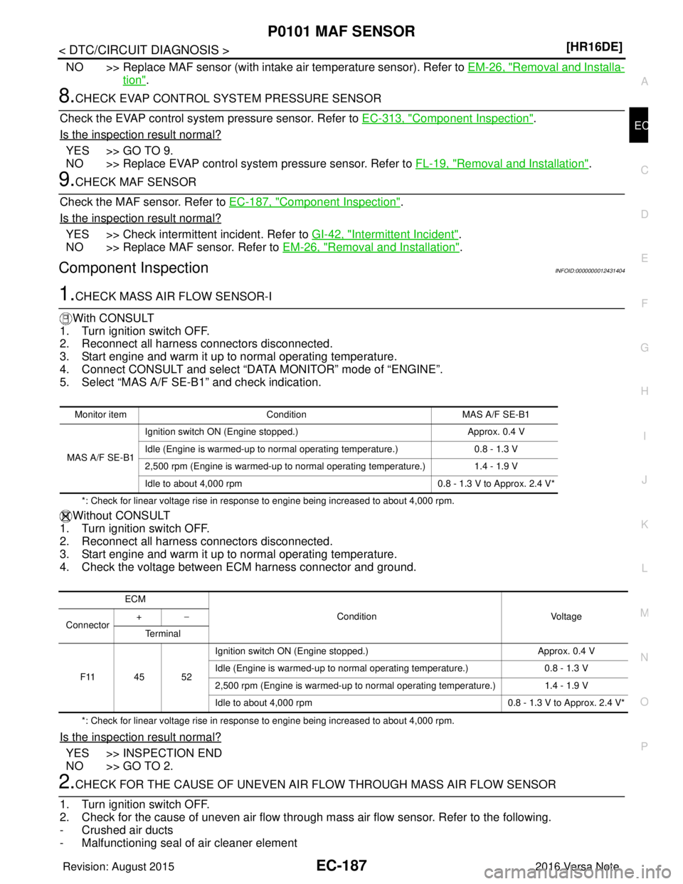
1.CHECK MASS AIR FLOW SENSOR-I
With CONSULT
1. Turn ignition switch OFF.
2. Reconnect all harness connectors disconnected.
3. Start engine and warm it up to normal operating temperature.
4. Connect CONSULT and select “DATA MONITOR” mode of “ENGINE”.
5. Select “MAS A/F SE-B1” and check indication.
*: Check for linear voltage rise in response to engine being increased to about 4,000 rpm.
Without CONSULT
1. Turn ignition switch OFF.
2. Reconnect all harness connectors disconnected.
3. Start engine and warm it up to normal operating temperature.
4. Check the voltage between ECM harness connector and ground.
*: Check for linear voltage rise in response to engine being increased to about 4,000 rpm.
Is the inspection result normal?
YES >> INSPECTION END
NO >> GO TO 2.
2.CHECK FOR THE CAUSE OF UNEVEN AIR FLOW THROUGH MASS AIR FLOW SENSOR
1. Turn ignition switch OFF.
2. Check for the cause of uneven air flow through mass air flow sensor. Refer to the following.
- Crushed air ducts
- Malfunctioning seal of air cleaner element
Monitor item Condition MAS A/F SE-B1
MAS A/F SE-B1 Ignition switch ON (Engine stopped.)
Approx. 0.4 V
Idle (Engine is warmed-up to normal operating temperature.) 0.8 - 1.3 V
2,500 rpm (Engine is warmed-up to normal operating temperature.) 1.4 - 1.9 V
Idle to about 4,000 rpm 0.8 - 1.3 V to Approx. 2.4 V*
ECM
Condition Voltage
Connector +
−
Te r m i n a l
F11 45 52 Ignition switch ON (Engine stopped.)
Approx. 0.4 V
Idle (Engine is warmed-up to normal operating temperature.) 0.8 - 1.3 V
2,500 rpm (Engine is warmed-up to normal operating temperature.) 1.4 - 1.9 V
Idle to about 4,000 rpm 0.8 - 1.3 V to Approx. 2.4 V*
Revision: August 2015 2016 Versa Note
cardiagn.com
Page 1315 of 3641
EC-188
< DTC/CIRCUIT DIAGNOSIS >[HR16DE]
P0101 MAF SENSOR
- Uneven dirt of air cleaner element
- Improper specification of intake air system parts
Is the inspection result normal?
YES >> GO TO 4.
NO >> GO TO 3.
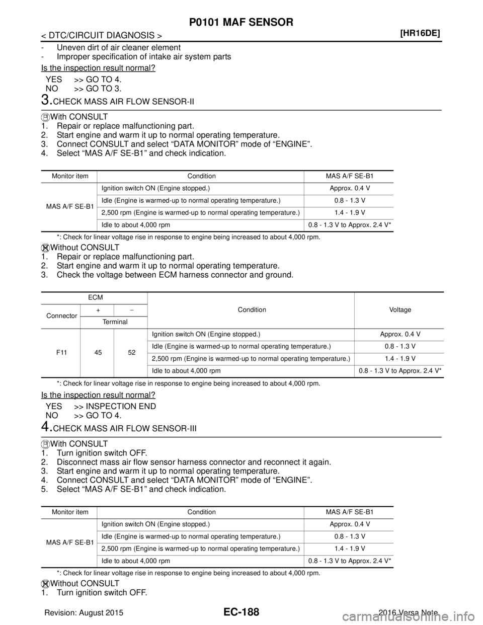
3.CHECK MASS AIR FLOW SENSOR-II
With CONSULT
1. Repair or replace malfunctioning part.
2. Start engine and warm it up to normal operating temperature.
3. Connect CONSULT and select “DATA MONITOR” mode of “ENGINE”.
4. Select “MAS A/F SE-B1” and check indication.
*: Check for linear voltage rise in response to engine being increased to about 4,000 rpm.
Without CONSULT
1. Repair or replace malfunctioning part.
2. Start engine and warm it up to normal operating temperature.
3. Check the voltage between ECM harness connector and ground.
*: Check for linear voltage rise in response to engine being increased to about 4,000 rpm.
Is the inspection result normal?
YES >> INSPECTION END
NO >> GO TO 4.
4.CHECK MASS AIR FLOW SENSOR-III
With CONSULT
1. Turn ignition switch OFF.
2. Disconnect mass air flow sensor harness connector and reconnect it again.
3. Start engine and warm it up to normal operating temperature.
4. Connect CONSULT and select “DATA MONITOR” mode of “ENGINE”.
5. Select “MAS A/F SE-B1” and check indication.
*: Check for linear voltage rise in response to engine being increased to about 4,000 rpm.
Without CONSULT
1. Turn ignition switch OFF.
Monitor item Condition MAS A/F SE-B1
MAS A/F SE-B1 Ignition switch ON (Engine stopped.)
Approx. 0.4 V
Idle (Engine is warmed-up to normal operating temperature.) 0.8 - 1.3 V
2,500 rpm (Engine is warmed-up to normal operating temperature.) 1.4 - 1.9 V
Idle to about 4,000 rpm 0.8 - 1.3 V to Approx. 2.4 V*
ECM
Condition Voltage
Connector +
−
Te r m i n a l
F11 45 52 Ignition switch ON (Engine stopped.)
Approx. 0.4 V
Idle (Engine is warmed-up to normal operating temperature.) 0.8 - 1.3 V
2,500 rpm (Engine is warmed-up to normal operating temperature.) 1.4 - 1.9 V
Idle to about 4,000 rpm 0.8 - 1.3 V to Approx. 2.4 V*
Monitor itemCondition MAS A/F SE-B1
MAS A/F SE-B1 Ignition switch ON (Engine stopped.)
Approx. 0.4 V
Idle (Engine is warmed-up to normal operating temperature.) 0.8 - 1.3 V
2,500 rpm (Engine is warmed-up to normal operating temperature.) 1.4 - 1.9 V
Idle to about 4,000 rpm 0.8 - 1.3 V to Approx. 2.4 V*
Revision: August 2015 2016 Versa Note
cardiagn.com
Page 1316 of 3641
P0101 MAF SENSOREC-189
< DTC/CIRCUIT DIAGNOSIS > [HR16DE]
C
D
E
F
G H
I
J
K L
M A
EC
NP
O
2. Disconnect mass air flow sensor har
ness connector and reconnect it again.
3. Start engine and warm it up to normal operating temperature.
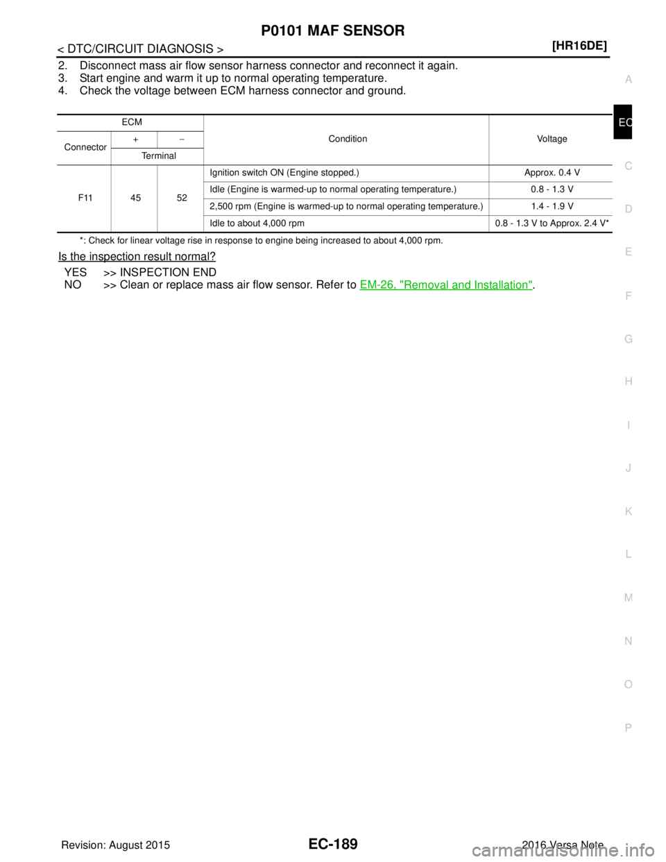
4. Check the voltage between ECM harness connector and ground.
*: Check for linear voltage rise in response to engine being increased to about 4,000 rpm.
Is the inspection result normal?
YES >> INSPECTION END
NO >> Clean or replace mass air flow sensor. Refer to EM-26, "
Removal and Installation".
ECM
Condition Voltage
Connector +
−
Te r m i n a l
F11 45 52 Ignition switch ON (Engine stopped.)
Approx. 0.4 V
Idle (Engine is warmed-up to normal operating temperature.) 0.8 - 1.3 V
2,500 rpm (Engine is warmed-up to normal operating temperature.) 1.4 - 1.9 V
Idle to about 4,000 rpm 0.8 - 1.3 V to Approx. 2.4 V*
Revision: August 2015 2016 Versa Note
cardiagn.com