engine start stop NISSAN NOTE 2016 Service Manual PDF
[x] Cancel search | Manufacturer: NISSAN, Model Year: 2016, Model line: NOTE, Model: NISSAN NOTE 2016Pages: 3641, PDF Size: 28.72 MB
Page 1319 of 3641
EC-192
< DTC/CIRCUIT DIAGNOSIS >[HR16DE]
P0102, P0103 MAF SENSOR
YES >> GO TO 8.
NO >> Replace mass air flow sensor. Refer to
EM-26, "
Removal and Installation".
8.CHECK INTERMITTENT INCIDENT
Refer to GI-42, "
Intermittent Incident".
>> INSPECTION END
Component InspectionINFOID:0000000012431407
1.CHECK MASS AIR FLOW SENSOR-I
With CONSULT
1. Turn ignition switch OFF.
2. Reconnect all harness connectors disconnected.
3. Start engine and warm it up to normal operating temperature.
4. Connect CONSULT and select “DATA MONITOR” mode.
5. Select “MAS A/F SE-B1” and check indication.
*: Check for linear voltage rise in response to engine being increased to about 4,000 rpm.
Without CONSULT
1. Turn ignition switch OFF.
2. Reconnect all harness connectors disconnected.
3. Start engine and warm it up to normal operating temperature.
4. Check the voltage between ECM harness connector and ground.
*: Check for linear voltage rise in response to engine being increased to about 4,000 rpm.
Is the inspection result normal?
YES >> INSPECTION END
NO >> GO TO 2.
2.CHECK FOR THE CAUSE OF UNEVEN AIR FL OW THROUGH MASS AIR FLOW SENSOR
1. Turn ignition switch OFF.
2. Check for the cause of uneven air flow through mass air flow sensor. Refer to the following.
- Crushed air ducts
- Malfunctioning seal of air cleaner element
- Uneven dirt of air cleaner element
- Improper specification of intake air system parts
Is the inspection result normal?
YES >> GO TO 4.
NO >> GO TO 3.
3.CHECK MASS AIR FLOW SENSOR-II
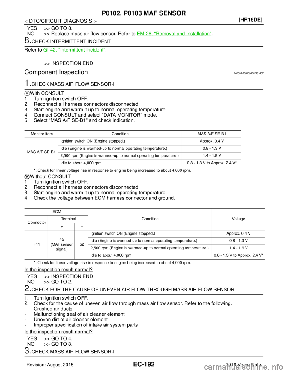
Monitor item Condition MAS A/F SE-B1
MAS A/F SE-B1 Ignition switch ON (Engine stopped.)
Approx. 0.4 V
Idle (Engine is warmed-up to normal operating temperature.) 0.8 - 1.3 V
2,500 rpm (Engine is warmed-up to normal operating temperature.) 1.4 - 1.9 V
Idle to about 4,000 rpm 0.8 - 1.3 V to Approx. 2.4 V*
ECM
Condition Voltage
Connector Te r m i n a l
+ −
F11 45
(MAF sensor signal) 52Ignition switch ON (Engine stopped.)
Approx. 0.4 V
Idle (Engine is warmed-up to normal operating temperature.) 0.8 - 1.3 V
2,500 rpm (Engine is warmed-up to normal operating temperature.) 1.4 - 1.9 V
Idle to about 4,000 rpm 0.8 - 1.3 V to Approx. 2.4 V*
Revision: August 2015 2016 Versa Note
cardiagn.com
Page 1320 of 3641
P0102, P0103 MAF SENSOREC-193
< DTC/CIRCUIT DIAGNOSIS > [HR16DE]
C
D
E
F
G H
I
J
K L
M A
EC
NP
O
With CONSULT
1. Repair or replace malfunctioning part.
2. Start engine and warm it up to normal operating temperature.
3. Connect CONSULT and select “DATA MONITOR” mode.
4. Select “MAS A/F SE-B1” and check indication.
*: Check for linear voltage rise in response to engine being increased to about 4,000 rpm.
Without CONSULT
1. Repair or replace malfunctioning part.
2. Start engine and warm it up to normal operating temperature.
3. Check the voltage between ECM harness connector and ground.
*: Check for linear voltage rise in response to engine being increased to about 4,000 rpm.
Is the inspection result normal?
YES >> INSPECTION END
NO >> GO TO 4.
4.CHECK MASS AIR FLOW SENSOR-III
With CONSULT
1. Turn ignition switch OFF.
2. Disconnect mass air flow sensor har ness connector and reconnect it again.
3. Start engine and warm it up to normal operating temperature.
4. Connect CONSULT and select “DATA MONITOR” mode.
5. Select “MAS A/F SE-B1” and check indication.
*: Check for linear voltage rise in response to engine being increased to about 4,000 rpm.
Without CONSULT
1. Turn ignition switch OFF.
2. Disconnect mass air flow sensor har ness connector and reconnect it again.
3. Start engine and warm it up to normal operating temperature.
4. Check the voltage between ECM harness connector and ground.
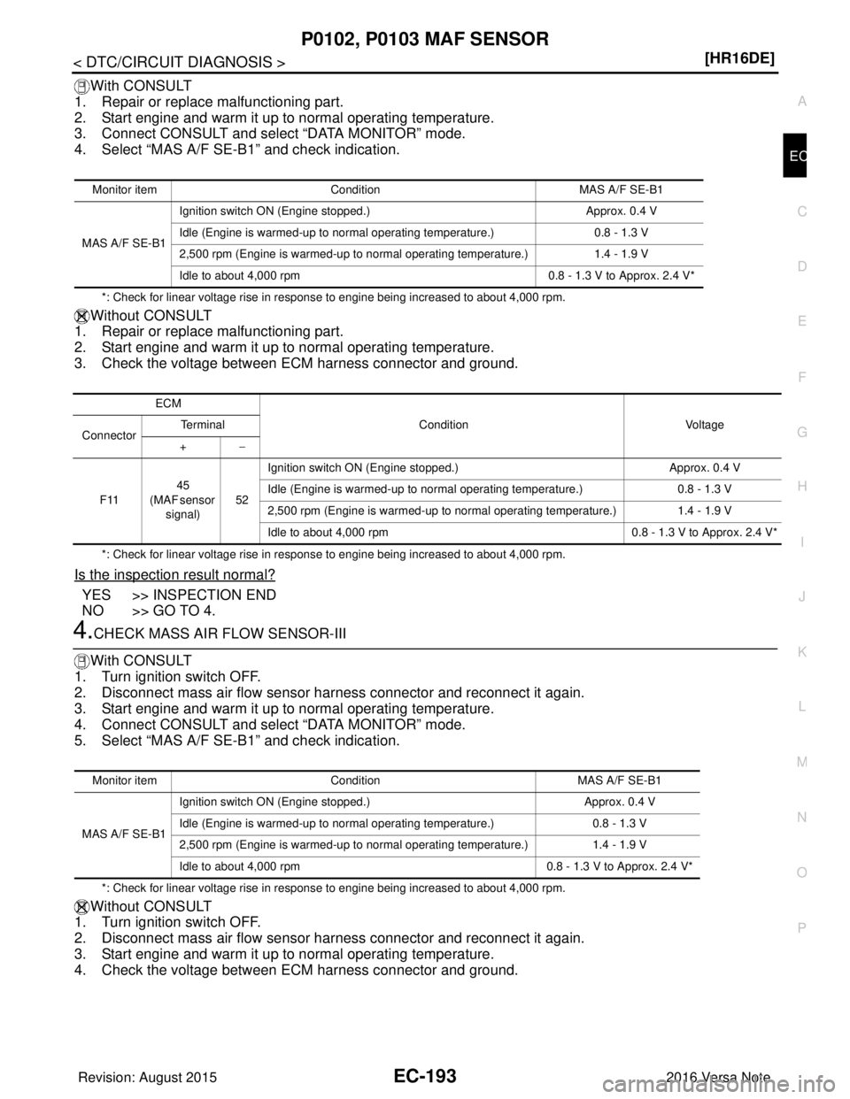
Monitor item Condition MAS A/F SE-B1
MAS A/F SE-B1 Ignition switch ON (Engine stopped.)
Approx. 0.4 V
Idle (Engine is warmed-up to normal operating temperature.) 0.8 - 1.3 V
2,500 rpm (Engine is warmed-up to normal operating temperature.) 1.4 - 1.9 V
Idle to about 4,000 rpm 0.8 - 1.3 V to Approx. 2.4 V*
ECM
Condition Voltage
Connector Te r m i n a l
+ −
F11 45
(MAF sensor signal) 52Ignition switch ON (Engine stopped.)
Approx. 0.4 V
Idle (Engine is warmed-up to normal operating temperature.) 0.8 - 1.3 V
2,500 rpm (Engine is warmed-up to normal operating temperature.) 1.4 - 1.9 V
Idle to about 4,000 rpm 0.8 - 1.3 V to Approx. 2.4 V*
Monitor itemCondition MAS A/F SE-B1
MAS A/F SE-B1 Ignition switch ON (Engine stopped.)
Approx. 0.4 V
Idle (Engine is warmed-up to normal operating temperature.) 0.8 - 1.3 V
2,500 rpm (Engine is warmed-up to normal operating temperature.) 1.4 - 1.9 V
Idle to about 4,000 rpm 0.8 - 1.3 V to Approx. 2.4 V*
Revision: August 2015 2016 Versa Note
cardiagn.com
Page 1333 of 3641
EC-206
< DTC/CIRCUIT DIAGNOSIS >[HR16DE]
P0125 ECT SENSOR
P0125 ECT SENSOR
DTC LogicINFOID:0000000012431425
DTC DETECTION LOGIC
NOTE:
•
If DTC P0125 is displayed with P0116, first perfo rm the trouble diagnosis for DTC P0116. Refer to EC-
199, "DTC Logic".
• If DTC P0125 is displayed with P0117 or P0118, fi rst perform the trouble diagnosis for DTC P0117 or
P0118. Refer to EC-201, "
DTC Logic".
DTC CONFIRMATION PROCEDURE
1.PRECONDITIONING
If DTC Confirmation Procedure has been previously conducted, always perform the following procedure
before conducting the next test.
1. Turn ignition switch OFF and wait at least 10 seconds.
2. Turn ignition switch ON.
3. Turn ignition switch OFF and wait at least 10 seconds.
>> GO TO 2.
2.CHECK ENGINE COOLANT TEMPERATURE SENSOR FUNCTION
With CONSULT
1. Turn ignition switch ON.
2. Select “DATA MONITOR” mode of “ENGINE” using CONSULT.
3. Check “COOLAN TEMP/S”.
With GST
Follow the procedure “With CONSULT” above.
Is it above
−6°C [21°F(for CVT)] or 5°C [41°F(forM/T)]?
YES >> INSPECTION END
NO >> GO TO 3.
3.PERFORM DTC CONFIRMATION PROCEDURE
With CONSULT
1. Start engine and run it for 65 minutes at idle speed.
2. Check 1st tip DTC.
If “COOLAN TEMP/S” indication increases to more than 10 °C (50° F) within 65 minutes, stop engine
because the test result will be OK.
CAUTION:
Be careful not to overheat engine.
With GST
Follow the procedure “With CONSULT” above.
Is 1st trip DTC detected?
YES >> Proceed to EC-206, "Diagnosis Procedure".
NO >> INSPECTION END
Diagnosis ProcedureINFOID:0000000012431426
1.CHECK ENGINE COOLANT TEMPERATURE SENSOR
DTC No. CONSULT screen terms
(Trouble diagnosis content) DTC detecting condition
Possible cause
P0125 ECT SENSOR
(Insufficient engine coolant
temperature for closed loop
fuel control) • Voltage sent to ECM from the sensor is not
practical, even when some time has passed
after starting the engine.
• Engine coolant temperature is insufficient for
closed loop fuel control. • Harness or connectors
(High resistance in the circuit)
• Engine coolant temperature sensor
•Thermostat
Revision: August 2015 2016 Versa Note
cardiagn.com
Page 1341 of 3641
EC-214
< DTC/CIRCUIT DIAGNOSIS >[HR16DE]
P0130 A/F SENSOR 1
Never apply brake when releasing the accelerator pedal.
Which does
“TESTING” change to?
COMPLETED>>GO TO 5.
OUT OF CONDITION>>Retry DTC CONFIRMATION PROCEDURE. GO TO 3.
5.PERFORM DTC CONFIRMATION PROCEDURE FOR MALFUNCTION -III
Touch “SELF-DIAG RESULT”.
Which is displayed on CONSULT screen?
OK >> INSPECTION END
NG >> Go to EC-214, "
Diagnosis Procedure".
6.PERFORM COMPONENT FUNCTIO N CHECK FOR MALFUNCTION
Perform component function check. Refer to EC-214, "
Component Function Check".
NOTE:
Use component function check to check the overall function of the A/F sensor 1 circuit. During this check, a
1st trip DTC might not be confirmed.
Is the inspection result normal?
YES >> INSPECTION END
NO >> Go to EC-214, "
Diagnosis Procedure".
Component Function CheckINFOID:0000000012431435
1.PERFORM COMPONENT FUNCTION CHECK
With GST
1. Start engine and warm it up to normal operating temperature.
2. Drive the vehicle at a speed of 80 km/h (50 MPH) for a few minutes in the suitable gear position.
3. Shift the selector lever to D position (CVT) or 5t h position (M/T), then release the accelerator pedal fully
until the vehicle speed decreases to 50 km/h (30 MPH).
CAUTION:
Always drive vehicle at a safe speed.
NOTE:
Never apply brake when releasing the accelerator pedal.
4. Repeat steps 2 and 3 for five times.
5. Stop the vehicle and turn ignition switch OFF.
6. Turn ignition switch ON.
7. Turn ignition switch OFF and wait at least 10 seconds.
8. Restart engine.
9. Repeat steps 2 and 3 for five times.
10. Stop the vehicle and connect GST to the vehicle.
11. Check 1st trip DTC.
Is 1st trip DTC detected?
YES >> Go to EC-214, "Diagnosis Procedure".
NO >> INSPECTION END
Diagnosis ProcedureINFOID:0000000012431436
1.CHECK GROUND CONNECTION
1. Turn ignition switch OFF.
2. Check ground connection E15. Refer to Ground Inspection in GI-44, "
Circuit Inspection".
Is the inspection result normal?
YES >> GO TO 2.
NO >> Repair or replace ground connection.
2.CHECK AIR FUEL RATIO (A/F) SENSOR 1 POWER SUPPLY CIRCUIT
1. Disconnect A/F sensor 1 harness connector.
2. Turn ignition switch ON.
3. Check the voltage between A/F sensor 1 harness connector and ground.
Revision: August 2015 2016 Versa Note
cardiagn.com
Page 1398 of 3641
P0300, P0301, P0302, P0303, P0304 MISFIRE
EC-271
< DTC/CIRCUIT DIAGNOSIS > [HR16DE]
C
D
E
F
G H
I
J
K L
M A
EC
NP
O
NO >> GO TO 3.
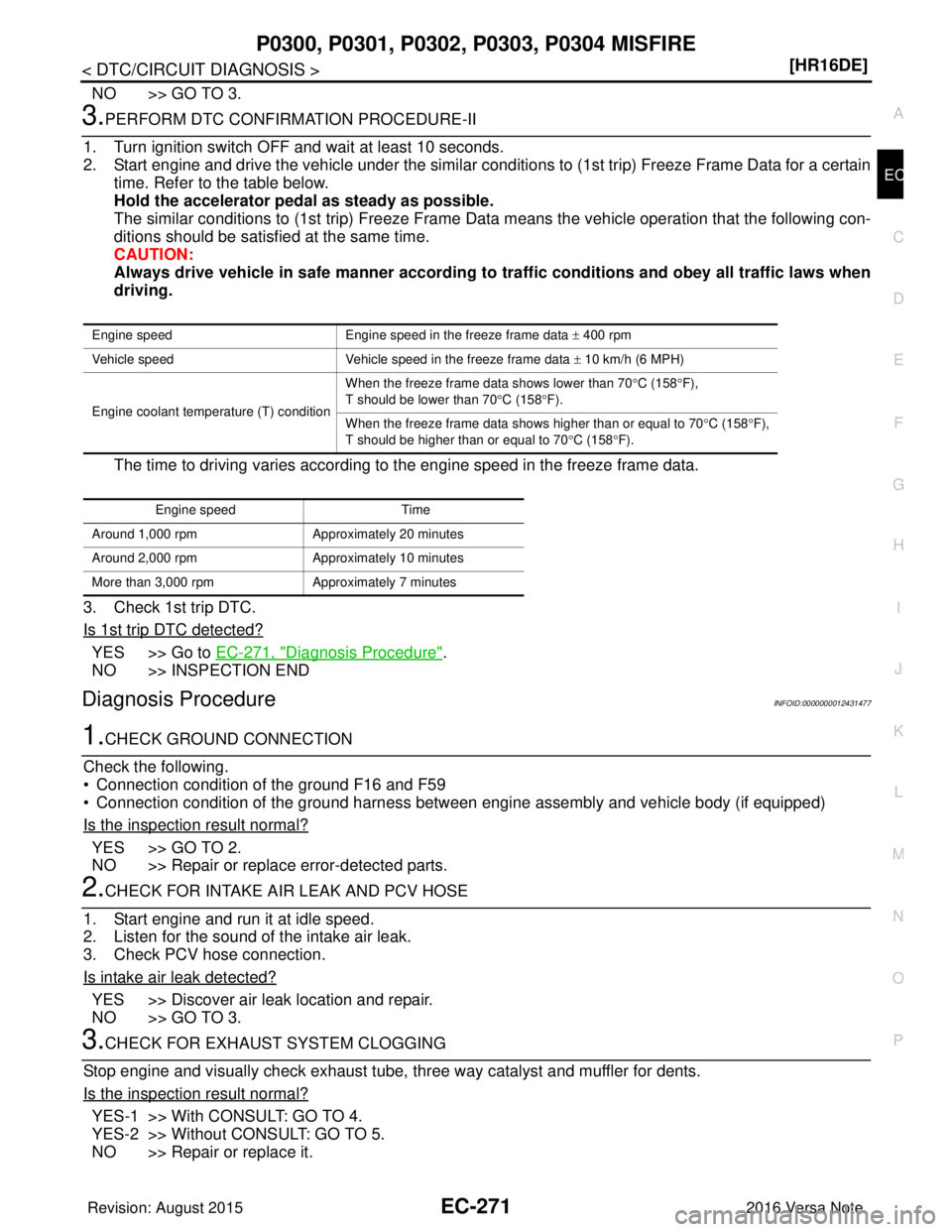
3.PERFORM DTC CONFIRMATION PROCEDURE-II
1. Turn ignition switch OFF and wait at least 10 seconds.
2. Start engine and drive the vehicle under the similar conditi ons to (1st trip) Freeze Frame Data for a certain
time. Refer to the table below.
Hold the accelerator pedal as steady as possible.
The similar conditions to (1st trip) Freeze Frame Da ta means the vehicle operation that the following con-
ditions should be satisfied at the same time.
CAUTION:
Always drive vehicle in safe manner according to traffic conditions and obey all traffic laws when
driving.
The time to driving varies according to the engine speed in the freeze frame data.
3. Check 1st trip DTC.
Is 1st trip DTC detected?
YES >> Go to EC-271, "Diagnosis Procedure".
NO >> INSPECTION END
Diagnosis ProcedureINFOID:0000000012431477
1.CHECK GROUND CONNECTION
Check the following.
• Connection condition of the ground F16 and F59
• Connection condition of the ground harness between engine assembly and vehicle body (if equipped)
Is the inspection result normal?
YES >> GO TO 2.
NO >> Repair or replace error-detected parts.
2.CHECK FOR INTAKE AIR LEAK AND PCV HOSE
1. Start engine and run it at idle speed.
2. Listen for the sound of the intake air leak.
3. Check PCV hose connection.
Is intake air leak detected?
YES >> Discover air leak location and repair.
NO >> GO TO 3.
3.CHECK FOR EXHAUST SYSTEM CLOGGING
Stop engine and visually check exhaust tube, three way catalyst and muffler for dents.
Is the inspection result normal?
YES-1 >> With CONSULT: GO TO 4.
YES-2 >> Without CONSULT: GO TO 5.
NO >> Repair or replace it.
Engine speed Engine speed in the freeze frame data ± 400 rpm
Vehicle speed Vehicle speed in the freeze frame data ± 10 km/h (6 MPH)
Engine coolant temperature (T) condition When the freeze frame data shows lower than 70°
C (158°F),
T should be lower than 70 °C (158 °F).
When the freeze frame data shows higher than or equal to 70 °C (158 °F),
T should be higher than or equal to 70° C (158°F).
Engine speed Time
Around 1,000 rpm Approximately 20 minutes
Around 2,000 rpm Approximately 10 minutes
More than 3,000 rpm Approximately 7 minutes
Revision: August 2015 2016 Versa Note
cardiagn.com
Page 1413 of 3641
EC-286
< DTC/CIRCUIT DIAGNOSIS >[HR16DE]
P0420 THREE WAY CATALYST FUNCTION
10. Check the indication of “CATALYST”.
Which is displayed on CONSULT screen?
CMPLT >> GO TO 6.
INCMP >> GO TO 4.
4.PERFORM DTC CONFIRMATION PROCEDURE-II
1. Wait 5 seconds at idle.
2. Rev engine up to 2,000 to 3,000 rpm and maintain it unt il “INCMP” of “CATALYST” changes to “CMPLT” (It
will take approximately 5 minutes).
Does the indication change to
“CMPLT”?
YES >> GO TO 6.
NO >> GO TO 5.
5.PERFORM DTC CONFIRMATION PROCEDURE AGAIN
1. Stop engine and cool it down to less than 70 °C (158° F).
2. Perform DTC CONFIRMATION PROCEDURE again.
>> GO TO 3.
6.PERFORM DTC CONFIRMATION PROCEDURE-III
Check 1st trip DTC.
Is 1st trip DTC detected?
YES >> Go to EC-287, "Diagnosis Procedure".
NO >> INSPECTION END
7.PERFORM COMPONENT FUNCTION CHECK
Perform component function check. Refer to EC-286, "
Component Function Check".
NOTE:
Use component function check to check the overall functi on of the three way catalyst (manifold). During this
check, a 1st trip DTC might not be confirmed.
Is the inspection result normal?
YES >> INSPECTION END
NO >> Go to EC-287, "
Diagnosis Procedure".
Component Function CheckINFOID:0000000012431488
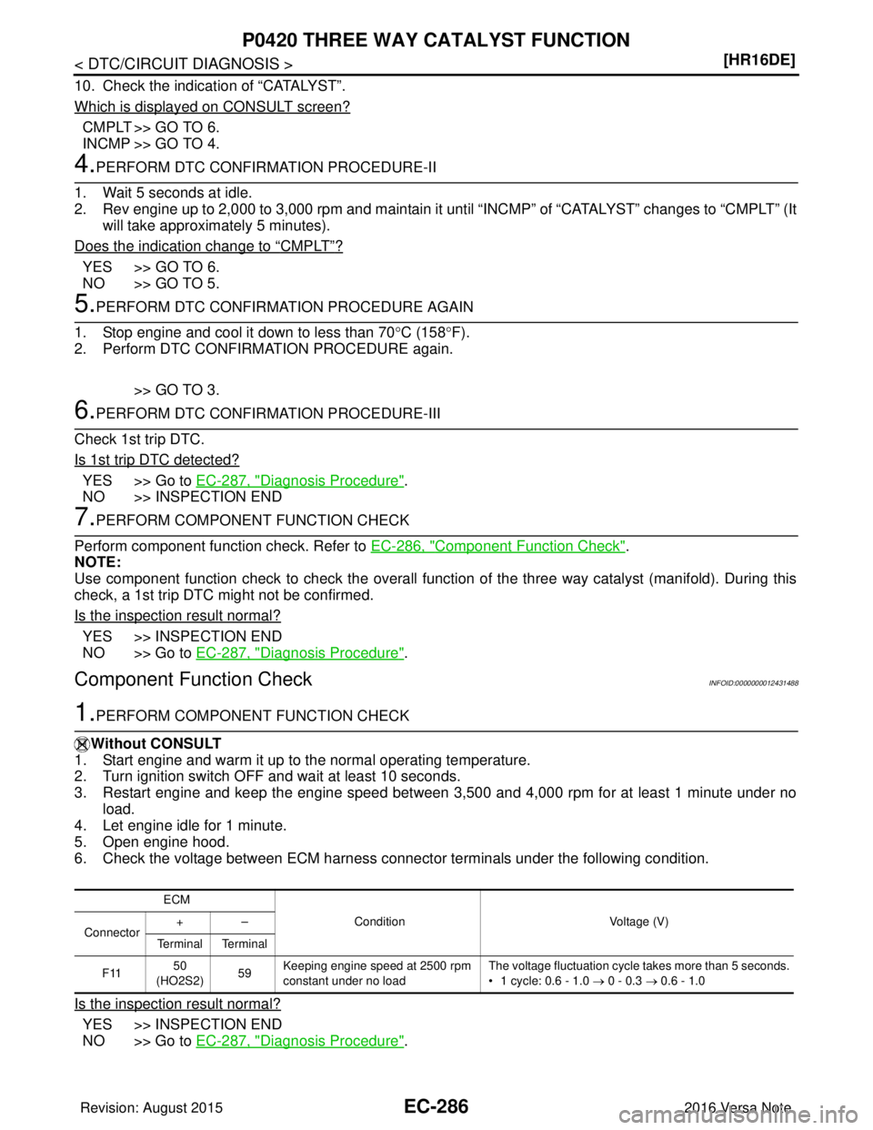
1.PERFORM COMPONENT FUNCTION CHECK
Without CONSULT
1. Start engine and warm it up to the normal operating temperature.
2. Turn ignition switch OFF and wait at least 10 seconds.
3. Restart engine and keep the engine speed between 3,500 and 4,000 rpm for at least 1 minute under no load.
4. Let engine idle for 1 minute.
5. Open engine hood.
6. Check the voltage between ECM harness connector terminals under the following condition.
Is the inspection result normal?
YES >> INSPECTION END
NO >> Go to EC-287, "
Diagnosis Procedure".
ECM
Condition Voltage (V)
Connector +–
Te r m i n a l Te r m i n a l
F11 50
(HO2S2) 59Keeping engine speed at 2500 rpm
constant under no load The voltage fluctuation cycle takes more than 5 seconds.
• 1 cycle: 0.6 - 1.0
→ 0 - 0.3 → 0.6 - 1.0
Revision: August 2015 2016 Versa Note
cardiagn.com
Page 1414 of 3641
P0420 THREE WAY CATALYST FUNCTIONEC-287
< DTC/CIRCUIT DIAGNOSIS > [HR16DE]
C
D
E
F
G H
I
J
K L
M A
EC
NP
O
Diagnosis ProcedureINFOID:0000000012431489
1.CHECK EXHAUST SYSTEM
Visually check exhaust tubes and muffler for dent.
Is the inspection result normal?
YES >> GO TO 2.
NO >> Repair or replace.
2.CHECK EXHAUST GAS LEAK
1. Start engine and run it at idle.
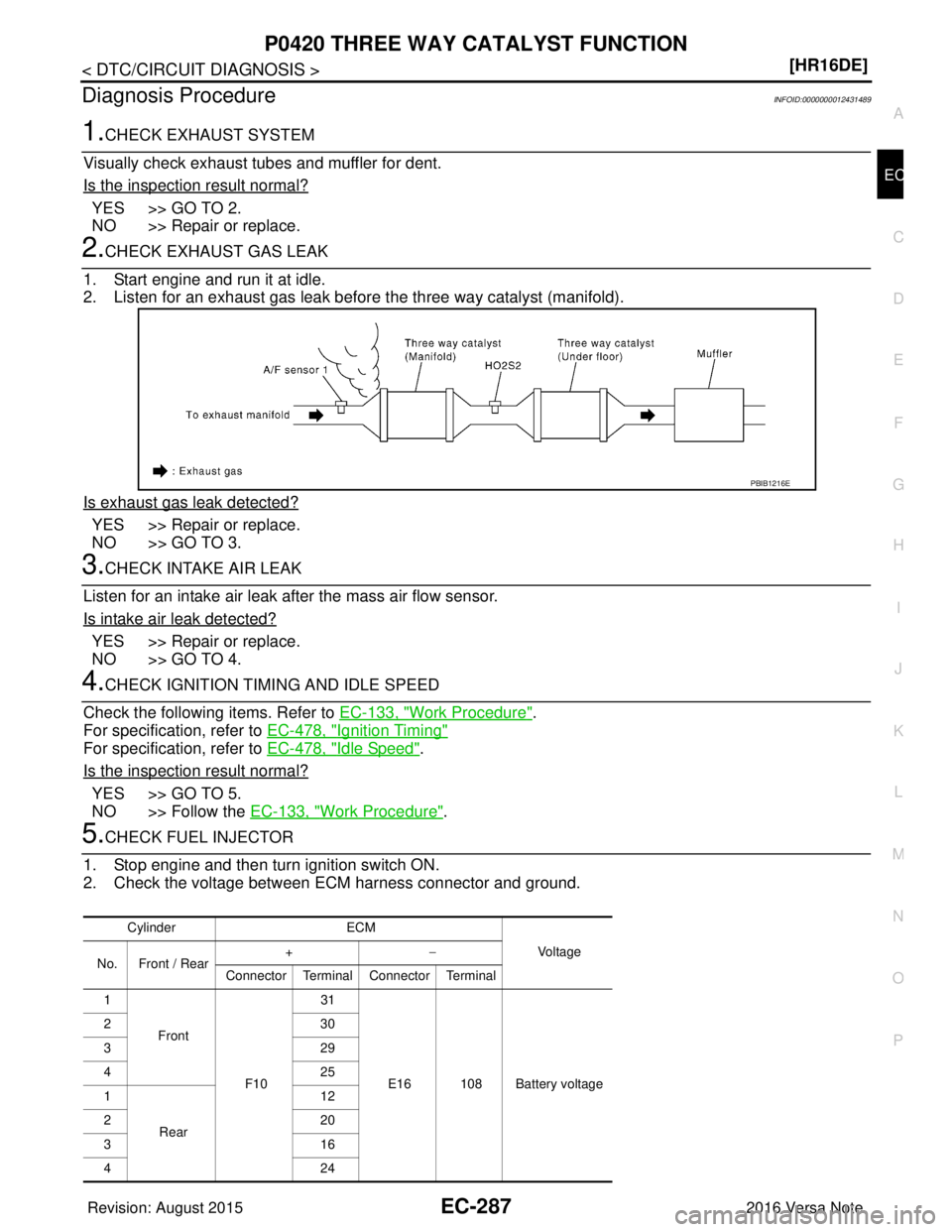
2. Listen for an exhaust gas leak before the three way catalyst (manifold).
Is exhaust gas leak detected?
YES >> Repair or replace.
NO >> GO TO 3.
3.CHECK INTAKE AIR LEAK
Listen for an intake air leak after the mass air flow sensor.
Is intake air leak detected?
YES >> Repair or replace.
NO >> GO TO 4.
4.CHECK IGNITION TIMI NG AND IDLE SPEED
Check the following items. Refer to EC-133, "
Work Procedure".
For specification, refer to EC-478, "
Ignition Timing"
For specification, refer to EC-478, "Idle Speed".
Is the inspection result normal?
YES >> GO TO 5.
NO >> Follow the EC-133, "
Work Procedure".
5.CHECK FUEL INJECTOR
1. Stop engine and then turn ignition switch ON.
2. Check the voltage between ECM harness connector and ground.
PBIB1216E
Cylinder ECM
Vol tag e
No. Front / Rear +
−
Connector Terminal Connector Terminal
1
Front
F1031
E16 108 Battery voltage
23
0
32 9
42 5
1
Rear 12
22 0
31 6
42 4
Revision: August 2015 2016 Versa Note
cardiagn.com
Page 1419 of 3641
EC-292
< DTC/CIRCUIT DIAGNOSIS >[HR16DE]
P0441 EVAP CONTROL SYSTEM
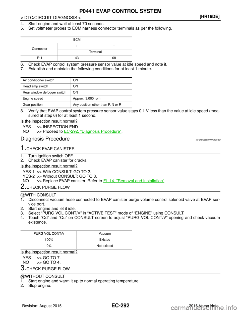
4. Start engine and wait at least 70 seconds.
5. Set voltmeter probes to ECM harness connector terminals as per the following.
6. Check EVAP control system pressure sensor value at idle speed and note it.
7. Establish and maintain the following conditions for at least 1 minute.
8. Verify that EVAP control system pressure sensor value stays 0.1 V less than the value at idle speed (mea-
sured at step 6) for at least 1 second.
Is the inspection result normal?
YES >> INSPECTION END
NO >> Proceed to EC-292, "
Diagnosis Procedure".
Diagnosis ProcedureINFOID:0000000012431492
1.CHECK EVAP CANISTER
1. Turn ignition switch OFF.
2. Check EVAP canister for cracks.
Is the inspection result normal?
YES-1 >> With CONSULT: GO TO 2.
YES-2 >> Without CONSULT: GO TO 3.
NO >> Replace EVAP canister. Refer to FL-14, "
Removal and Installation".
2.CHECK PURGE FLOW
WITH CONSULT
1. Disconnect vacuum hose connected to EVAP canister purge volume control solenoid valve at EVAP ser-
vice port.
2. Start engine and let it idle.
3. Select “PURG VOL CONT/V” in “ACTIVE TEST” mode of “ENGINE” using CONSULT.
4. Touch “Qd” and “Qu” on CONSULT screen to adjust “PURG VOL CONT/V” opening and check vacuum existence.
Is the inspection result normal?
YES >> GO TO 7.
NO >> GO TO 4.
3.CHECK PURGE FLOW
WITHOUT CONSULT
1. Start engine and warm it up to normal operating temperature.
2. Stop engine.
ECM
Connector +–
Te r m i n a l
F11 4368
Air conditioner switch ON
Headlamp switch ON
Rear window defogger switch ON
Engine speed Approx. 3,000 rpm
Gear position Any position other than P, N or R
PURG VOL CONT/V Vacuum
100% Existed
0% Not existed
Revision: August 2015 2016 Versa Note
cardiagn.com
Page 1422 of 3641
P0443 EVAP CANISTER PURGE VOLUME CONTROL SOLENOID VALVE
EC-295
< DTC/CIRCUIT DIAGNOSIS > [HR16DE]
C
D
E
F
G H
I
J
K L
M A
EC
NP
O
P0443 EVAP CANISTER PURGE VOLU
ME CONTROL SOLENOID VALVE
DTC LogicINFOID:0000000012431493
DTC DETECTION LOGIC
DTC CONFIRMATION PROCEDURE
1.PRECONDITIONING
If DTC Confirmation Procedure has been previously conducted, always perform the following procedure
before conducting the next test.
1. Turn ignition switch OFF and wait at least 10 seconds.
2. Turn ignition switch ON.
3. Turn ignition switch OFF and wait at least 10 seconds.
TESTING CONDITION:
• Perform DTC CONFIRMATION PROCEDURE when the fu el is between 1/4 and 3/4 full, and vehicle is
placed on flat level surface.
• Always perform test at a temperature of 5 to 60 °C (41 to 140 °F).
• Cool the vehicle so that engi ne coolant temperature becomes same level as ambient temperature.
Do you have CONSULT
YES >> GO TO 2.
NO >> GO TO 4.
2.PERFORM DTC CONFIRMATION PROCEDURE A
With CONSULT
1. Turn ignition switch ON.
2. Select “DATA MONITOR” mode of “ENGINE” using CONSULT.
3. Check that the following condition are met. FUEL T/TMP SE: 0 - 35 °C (32 - 95° F)
4. Start engine and wait at least 60 seconds.
5. Check 1st trip DTC.
Is 1st trip DTC detected?
YES >> Proceed to EC-296, "Diagnosis Procedure".
NO >> GO TO 3.
3.PERFORM DTC CONFIRMATION PROCEDURE B
With CONSULT
1. Start engine and warm it up to normal operating temperature.
2. Turn ignition switch OFF and wait at least 10 seconds.
3. Turn ignition switch ON.
4. Select “PURG VOL CN/V P1444” of “EVAPORATI VE SYSTEM” in “DTC WORK SUPPORT” mode of
“ENGINE” using CONSULT.
5. Touch “START”.
6. Start engine and let it idle until “TESTING” on CONSUL T changes to “COMPLETED”. (It will take approxi-
mately 10 seconds.)
If “TESTING” is not displayed afte r 5 minutes, retry from step 2.
7. Touch “SELF-DIAG RESULT”.
DTC No. CONSULT screen terms
(Trouble diagnosis content) DTC detecting condition
Possible cause
P0443 PURG VOLUME CONT/V
(EVAP canister purge volume
control solenoid valve) A
The canister purge flow is detected during
the vehicle is stopped while the engine is
running, even when EVAP canister purge
volume control solenoid valve is completely
closed. • EVAP control system pressure sensor
• EVAP canister purge volume control
solenoid valve
(The valve is stuck open.)
• EVAP canister vent control valve
• EVAP canister
• Hoses (Hoses are connected incorrectly or
clogged.)
B The canister purge flow is detected during
the specified driving conditions, even when
EVAP canister purge volume control sole-
noid valve is completely closed.
Revision: August 2015
2016 Versa Note
cardiagn.com
Page 1452 of 3641
P0456 EVAP CONTROL SYSTEMEC-325
< DTC/CIRCUIT DIAGNOSIS > [HR16DE]
C
D
E
F
G H
I
J
K L
M A
EC
NP
O
1. Remove EVAP canister (1) wit
h EVAP canister vent control
valve (2) and EVAP control syst em pressure sensor attached.
2. Check if water will drain from the EVAP canister.
Does water drain from EVAP canister?
YES >> GO TO 8.
NO-1 >> With CONSULT: GO TO 10.
NO-2 >> Without CONSULT: GO TO 11.
8.CHECK EVAP CANISTER
Weigh the EVAP canister assembly with the EVAP canist er vent control valve and EVAP control system pres-
sure sensor attached. Refer to FL-17, "
Removal and Installation".
The weight should be less than 1.6 kg (3.5 lb).
Is the inspection result normal?
YES-1 >> With CONSULT: GO TO 10.
YES-2 >> Without CONSULT: GO TO 11.
NO >> GO TO 9.
9.DETECT MALFUNCTIONING PART
Check the following.
• EVAP canister for damage
• EVAP hose between EVAP canister and vehi cle frame for clogging or poor connection
>> Repair hose or replace EVAP canister. Refer to FL-14, "
Removal and Installation".
10.CHECK EVAP CANISTER PURGE VOLUME CONTROL SOLENOID VALVE OPERATION
With CONSULT
1. Disconnect vacuum hose to EVAP canister purge volu me control solenoid valve at EVAP service port.
2. Start engine and let it idle.
3. Select “PURG VOL CONT/V” in “ACTIVE TEST” mode of “ENGINE” using CONSULT.
4. Touch “Qu” on CONSULT screen to in crease “PURG VOL CONT/V” opening to 100%.
5. Check vacuum hose for vacuum.
Is the inspection result normal?
YES >> GO TO 13.
NO >> GO TO 12.
11 .CHECK EVAP CANISTER PURGE VOLUME CONTROL SOLENOID VALVE OPERATION
Without CONSULT
1. Start engine and warm it up to normal operating temperature.
2. Stop engine.
3. Disconnect vacuum hose to EVAP canister purge volu me control solenoid valve at EVAP service port.
4. Start engine and let it idle for at least 80 seconds.
5. Check vacuum hose for vacuum when revving engine up to 2,000 rpm.
Is the inspection result normal?
YES >> GO TO 13.
NO >> GO TO 12.
12.CHECK VACUUM HOSE
Check vacuum hoses for clogging or disconnection. Refer to FL-14, "
Exploded View".
Is the inspection result normal?
PBIB2731E
Vacuum should exist.
Vacuum should exist.
Revision: August 2015 2016 Versa Note
cardiagn.com