ECU NISSAN PATROL 1998 Y61 / 5.G Body Workshop Manual
[x] Cancel search | Manufacturer: NISSAN, Model Year: 1998, Model line: PATROL, Model: NISSAN PATROL 1998 Y61 / 5.GPages: 55, PDF Size: 2.76 MB
Page 5 of 55
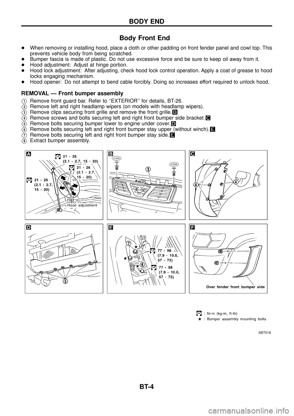
Body Front End
+When removing or installing hood, place a cloth or other padding on front fender panel and cowl top. This
prevents vehicle body from being scratched.
+Bumper fascia is made of plastic. Do not use excessive force and be sure to keep oil away from it.
+Hood adjustment: Adjust at hinge portion.
+Hood lock adjustment: After adjusting, check hood lock control operation. Apply a coat of grease to hood
locks engaging mechanism.
+Hood opener: Do not attempt to bend cable forcibly. Doing so increases effort required to unlock hood.
REMOVAL Ð Front bumper assembly
V1Remove front guard bar. Refer to ``EXTERIOR'' for details, BT-26.
V2Remove left and right headlamp wipers (on models with headlamp wipers).
V3Remove clips securing front grille and remove the front grille.
V4Remove screws and bolts securing left and right front bumper side bracket.
V5Remove bolts securing bumper lower to engine under cover.
V6Remove bolts securing left and right front bumper stay upper (without winch).
V7Remove bolts securing left and right front bumper stay side.
V8Extract bumper assembly.
SBT518
BODY END
BT-4
Page 7 of 55
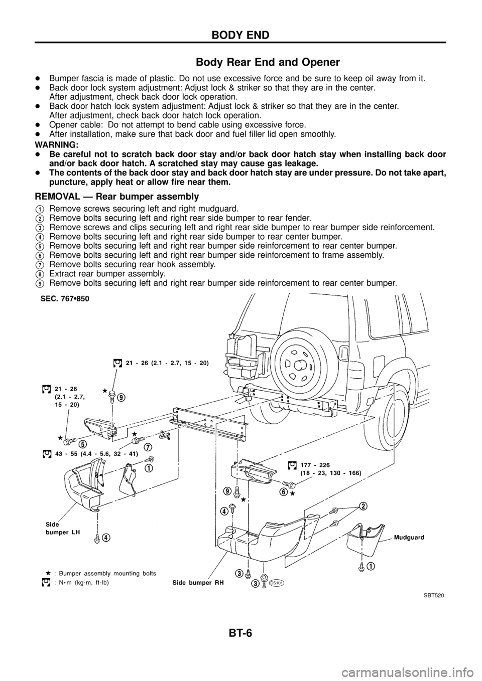
Body Rear End and Opener
+Bumper fascia is made of plastic. Do not use excessive force and be sure to keep oil away from it.
+Back door lock system adjustment: Adjust lock & striker so that they are in the center.
After adjustment, check back door lock operation.
+Back door hatch lock system adjustment: Adjust lock & striker so that they are in the center.
After adjustment, check back door hatch lock operation.
+Opener cable: Do not attempt to bend cable using excessive force.
+After installation, make sure that back door and fuel ®ller lid open smoothly.
WARNING:
+Be careful not to scratch back door stay and/or back door hatch stay when installing back door
and/or back door hatch. A scratched stay may cause gas leakage.
+The contents of the back door stay and back door hatch stay are under pressure. Do not take apart,
puncture, apply heat or allow ®re near them.
REMOVAL Ð Rear bumper assembly
V1Remove screws securing left and right mudguard.
V2Remove bolts securing left and right rear side bumper to rear fender.
V3Remove screws and clips securing left and right rear side bumper to rear bumper side reinforcement.
V4Remove bolts securing left and right rear side bumper to rear center bumper.
V5Remove bolts securing left and right rear bumper side reinforcement to rear center bumper.
V6Remove bolts securing left and right rear bumper side reinforcement to frame assembly.
V7Remove bolts securing rear hook assembly.
V8Extract rear bumper assembly.
V9Remove bolts securing left and right rear bumper side reinforcement to rear center bumper.
SBT520
BODY END
BT-6
Page 17 of 55
CAUTION:
Wrap the tip of ¯at-bladed screwdriver with a cloth when removing metal clips from garnishes.
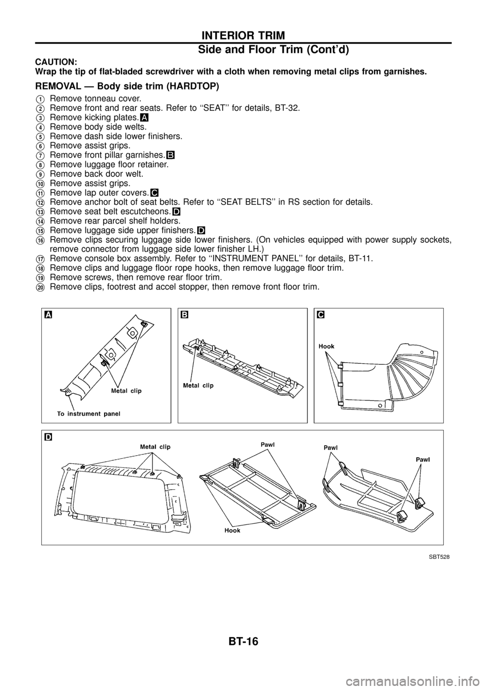
REMOVAL Ð Body side trim (HARDTOP)
V1Remove tonneau cover.
V2Remove front and rear seats. Refer to ``SEAT'' for details, BT-32.
V3Remove kicking plates.
V4Remove body side welts.
V5Remove dash side lower ®nishers.
V6Remove assist grips.
V7Remove front pillar garnishes.
V8Remove luggage ¯oor retainer.
V9Remove back door welt.
V10Remove assist grips.
V11Remove lap outer covers.
V12Remove anchor bolt of seat belts. Refer to ``SEAT BELTS'' in RS section for details.
V13Remove seat belt escutcheons.
V14Remove rear parcel shelf holders.
V15Remove luggage side upper ®nishers.
V16Remove clips securing luggage side lower ®nishers. (On vehicles equipped with power supply sockets,
remove connector from luggage side lower ®nisher LH.)
V17Remove console box assembly. Refer to ``INSTRUMENT PANEL'' for details, BT-11.
V18Remove clips and luggage ¯oor rope hooks, then remove luggage ¯oor trim.
V19Remove screws, then remove rear ¯oor trim.
V20Remove clips, footrest and accel stopper, then remove front ¯oor trim.
SBT528
INTERIOR TRIM
Side and Floor Trim (Cont'd)
BT-16
Page 19 of 55
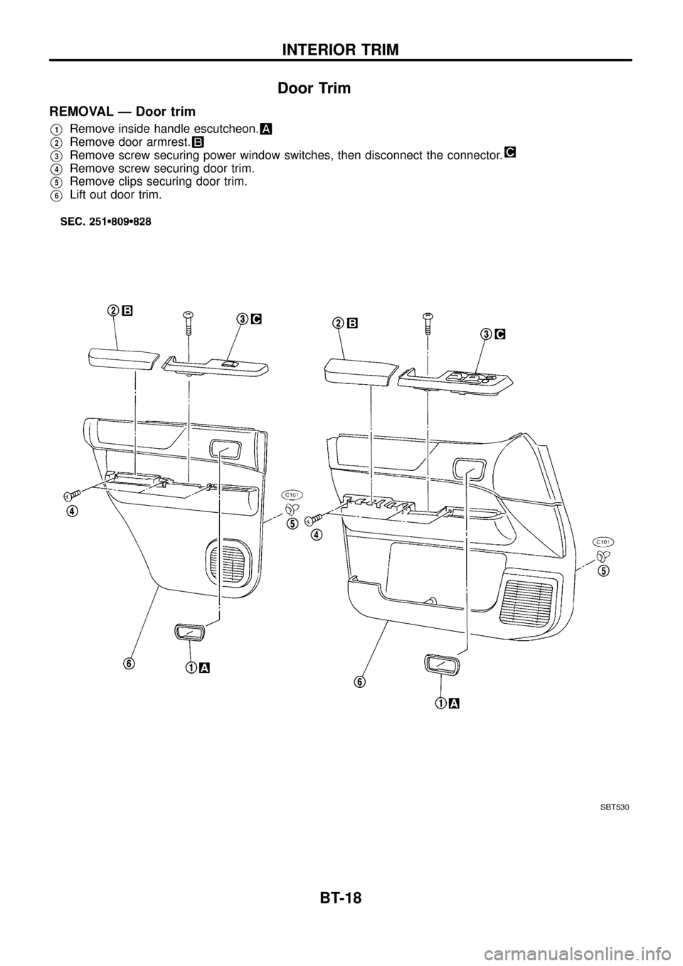
Door Trim
REMOVAL Ð Door trim
V1Remove inside handle escutcheon.
V2Remove door armrest.
V3Remove screw securing power window switches, then disconnect the connector.
V4Remove screw securing door trim.
V5Remove clips securing door trim.
V6Lift out door trim.
SBT530
INTERIOR TRIM
BT-18
Page 21 of 55
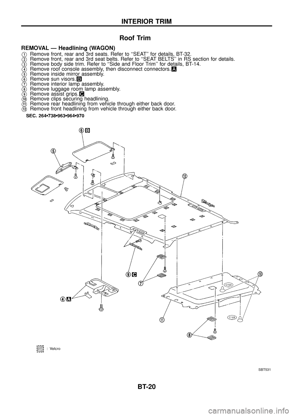
Roof Trim
REMOVAL Ð Headlining (WAGON)
V1Remove front, rear and 3rd seats. Refer to ``SEAT'' for details, BT-32.
V2Remove front, rear and 3rd seat belts. Refer to ``SEAT BELTS'' in RS section for details.
V3Remove body side trim. Refer to ``Side and Floor Trim'' for details, BT-14.
V4Remove roof console assembly, then disconnect connectors.
V5Remove inside mirror assembly.
V6Remove sun visors.
V7Remove interior lamp assembly.
V8Remove luggage room lamp assembly.
V9Remove assist grips.
V10Remove clips securing headlining.
V11Remove rear headlining from vehicle through either back door.
V12Remove front headlining from vehicle through either back door.
SBT531
INTERIOR TRIM
BT-20
Page 23 of 55
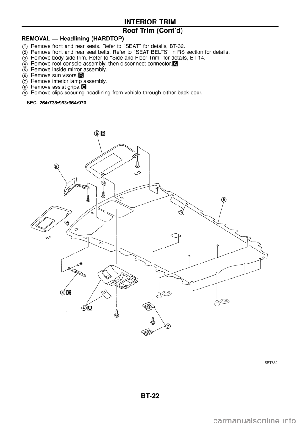
REMOVAL Ð Headlining (HARDTOP)
V1Remove front and rear seats. Refer to ``SEAT'' for details, BT-32.
V2Remove front and rear seat belts. Refer to ``SEAT BELTS'' in RS section for details.
V3Remove body side trim. Refer to ``Side and Floor Trim'' for details, BT-14.
V4Remove roof console assembly, then disconnect connector.
V5Remove inside mirror assembly.
V6Remove sun visors.
V7Remove interior lamp assembly.
V8Remove assist grips.
V9Remove clips securing headlining from vehicle through either back door.
SBT532
INTERIOR TRIM
Roof Trim (Cont'd)
BT-22
Page 25 of 55
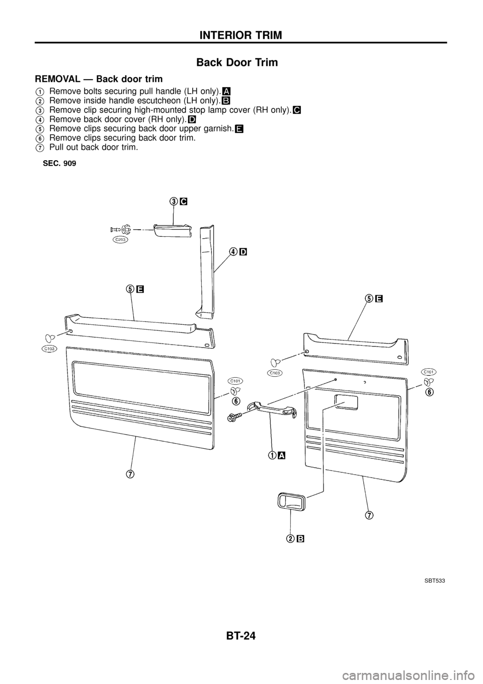
Back Door Trim
REMOVAL Ð Back door trim
V1Remove bolts securing pull handle (LH only).
V2Remove inside handle escutcheon (LH only).
V3Remove clip securing high-mounted stop lamp cover (RH only).
V4Remove back door cover (RH only).
V5Remove clips securing back door upper garnish.
V6Remove clips securing back door trim.
V7Pull out back door trim.
SBT533
INTERIOR TRIM
BT-24
Page 43 of 55
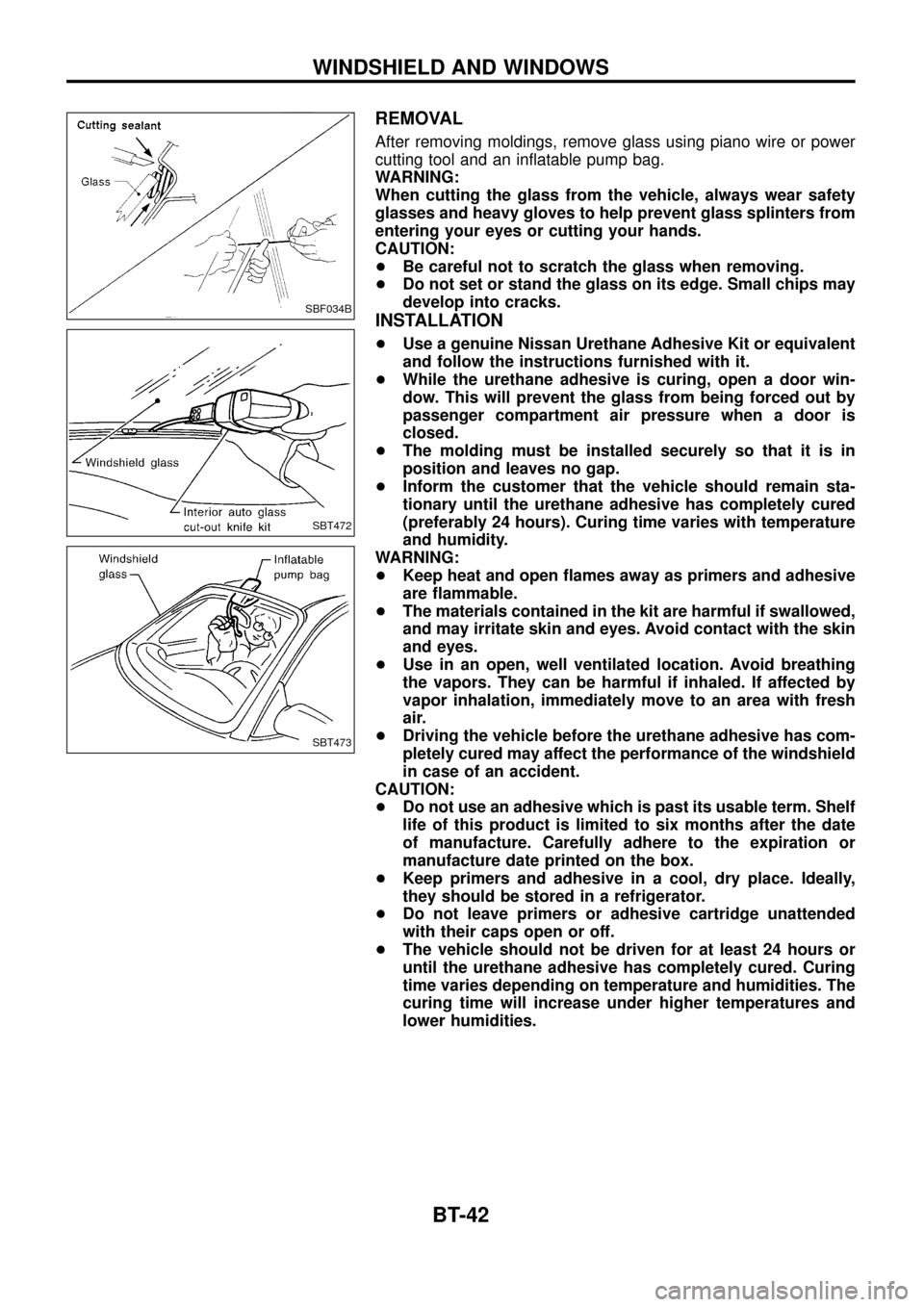
REMOVAL
After removing moldings, remove glass using piano wire or power
cutting tool and an in¯atable pump bag.
WARNING:
When cutting the glass from the vehicle, always wear safety
glasses and heavy gloves to help prevent glass splinters from
entering your eyes or cutting your hands.
CAUTION:
+Be careful not to scratch the glass when removing.
+Do not set or stand the glass on its edge. Small chips may
develop into cracks.
INSTALLATION
+Use a genuine Nissan Urethane Adhesive Kit or equivalent
and follow the instructions furnished with it.
+While the urethane adhesive is curing, open a door win-
dow. This will prevent the glass from being forced out by
passenger compartment air pressure when a door is
closed.
+The molding must be installed securely so that it is in
position and leaves no gap.
+Inform the customer that the vehicle should remain sta-
tionary until the urethane adhesive has completely cured
(preferably 24 hours). Curing time varies with temperature
and humidity.
WARNING:
+Keep heat and open ¯ames away as primers and adhesive
are ¯ammable.
+The materials contained in the kit are harmful if swallowed,
and may irritate skin and eyes. Avoid contact with the skin
and eyes.
+Use in an open, well ventilated location. Avoid breathing
the vapors. They can be harmful if inhaled. If affected by
vapor inhalation, immediately move to an area with fresh
air.
+Driving the vehicle before the urethane adhesive has com-
pletely cured may affect the performance of the windshield
in case of an accident.
CAUTION:
+Do not use an adhesive which is past its usable term. Shelf
life of this product is limited to six months after the date
of manufacture. Carefully adhere to the expiration or
manufacture date printed on the box.
+Keep primers and adhesive in a cool, dry place. Ideally,
they should be stored in a refrigerator.
+Do not leave primers or adhesive cartridge unattended
with their caps open or off.
+The vehicle should not be driven for at least 24 hours or
until the urethane adhesive has completely cured. Curing
time varies depending on temperature and humidities. The
curing time will increase under higher temperatures and
lower humidities.
SBF034B
SBT472
SBT473
WINDSHIELD AND WINDOWS
BT-42
Page 47 of 55

Door Mirror
CAUTION:
Be careful not to scratch door rearview mirror body.
.For Wiring Diagram, refer to ``POWER DOOR MIRROR'' in EL section.
REMOVAL Ð Door mirror
V1Remove door trim. Refer to ``Door Trim'' for details, BT-18.
V2Remove clip securing inner cover, then remove inner cover.
V3Roll back sealing screen and remove door mirror harness connector.
V4Remove door mirror harness clip.
V5Remove bolts securing door mirror, then remove door mirror assembly.
SBT559
MIRROR
BT-46