sen NISSAN PATROL 1998 Y61 / 5.G Electrical System Owner's Guide
[x] Cancel search | Manufacturer: NISSAN, Model Year: 1998, Model line: PATROL, Model: NISSAN PATROL 1998 Y61 / 5.GPages: 326, PDF Size: 11.36 MB
Page 247 of 326
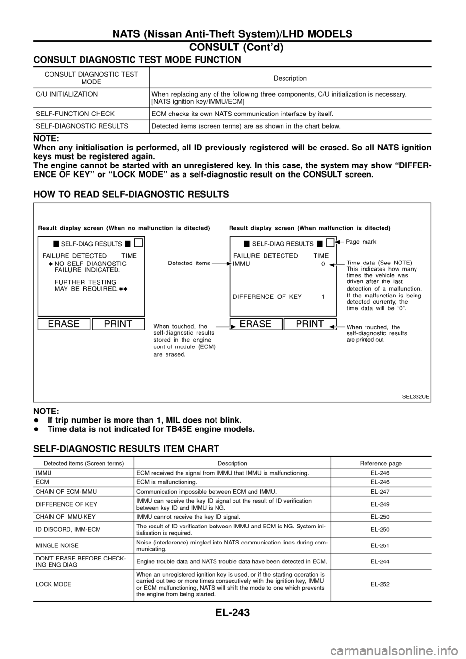
CONSULT DIAGNOSTIC TEST MODE FUNCTION
CONSULT DIAGNOSTIC TEST
MODEDescription
C/U INITIALIZATION When replacing any of the following three components, C/U initialization is necessary.
[NATS ignition key/IMMU/ECM]
SELF-FUNCTION CHECK ECM checks its own NATS communication interface by itself.
SELF-DIAGNOSTIC RESULTS Detected items (screen terms) are as shown in the chart below.
NOTE:
When any initialisation is performed, all ID previously registered will be erased. So all NATS ignition
keys must be registered again.
The engine cannot be started with an unregistered key. In this case, the system may show ``DIFFER-
ENCE OF KEY'' or ``LOCK MODE'' as a self-diagnostic result on the CONSULT screen.
HOW TO READ SELF-DIAGNOSTIC RESULTS
NOTE:
+If trip number is more than 1, MIL does not blink.
+Time data is not indicated for TB45E engine models.
SELF-DIAGNOSTIC RESULTS ITEM CHART
Detected items (Screen terms) Description Reference page
IMMU ECM received the signal from IMMU that IMMU is malfunctioning. EL-246
ECM ECM is malfunctioning. EL-246
CHAIN OF ECM-IMMU Communication impossible between ECM and IMMU. EL-247
DIFFERENCE OF KEYIMMU can receive the key ID signal but the result of ID veri®cation
between key ID and IMMU is NG.EL-249
CHAIN OF IMMU-KEY IMMU cannot receive the key ID signal. EL-250
ID DISCORD, IMM-ECMThe result of ID veri®cation between IMMU and ECM is NG. System ini-
tialisation is required.EL-250
MINGLE NOISENoise (interference) mingled into NATS communication lines during com-
municating.EL-251
DON'T ERASE BEFORE CHECK-
ING ENG DIAGEngine trouble data and NATS trouble data have been detected in ECM. EL-244
LOCK MODEWhen an unregistered ignition key is used, or if the starting operation is
carried out two or more times consecutively with the ignition key, IMMU
or ECM malfunctioning, NATS will shift the mode to one which prevents
the engine from being started.EL-252
SEL332UE
NATS (Nissan Anti-Theft System)/LHD MODELS
CONSULT (Cont'd)
EL-243
Page 262 of 326
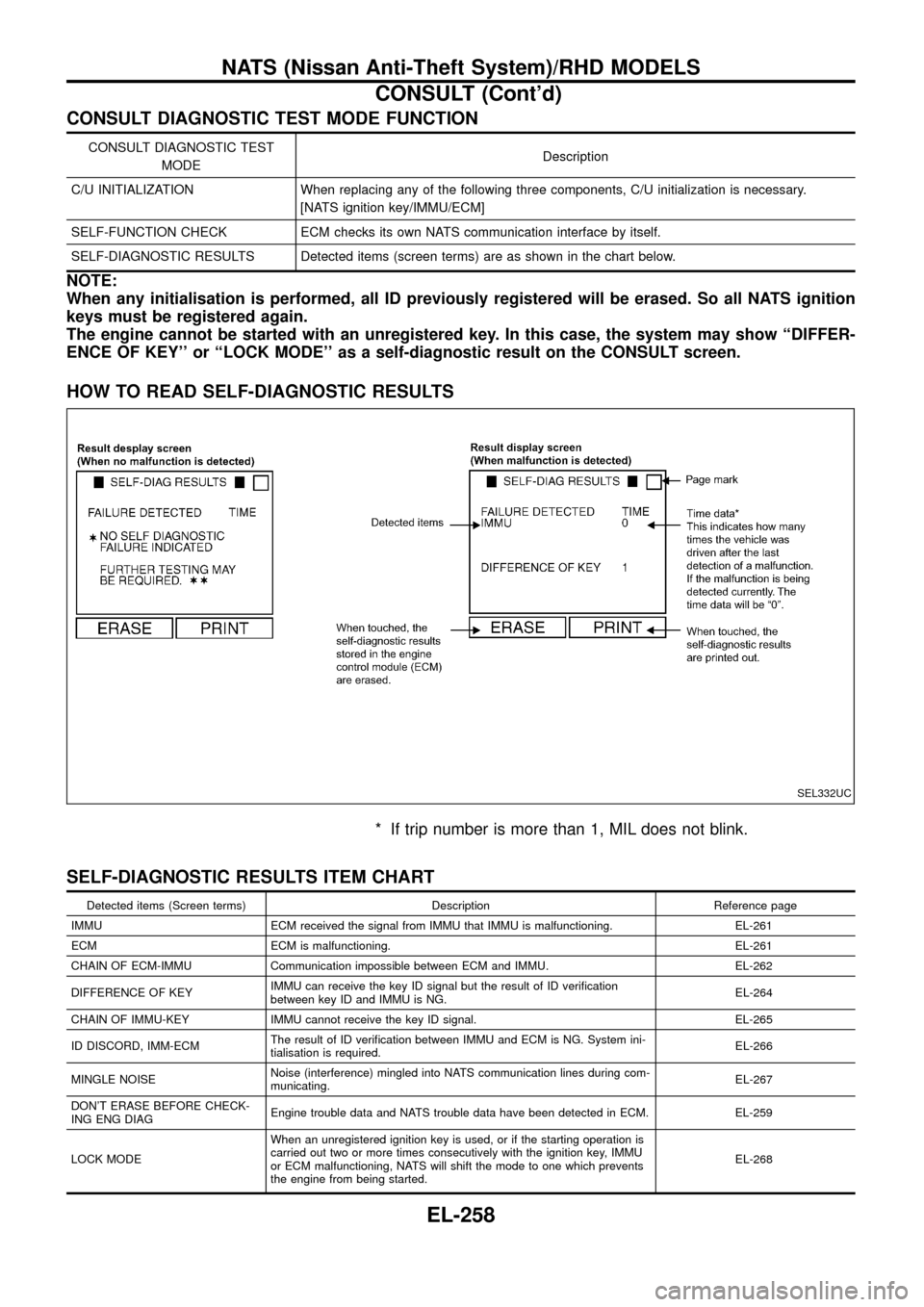
CONSULT DIAGNOSTIC TEST MODE FUNCTION
CONSULT DIAGNOSTIC TEST
MODEDescription
C/U INITIALIZATION When replacing any of the following three components, C/U initialization is necessary.
[NATS ignition key/IMMU/ECM]
SELF-FUNCTION CHECK ECM checks its own NATS communication interface by itself.
SELF-DIAGNOSTIC RESULTS Detected items (screen terms) are as shown in the chart below.
NOTE:
When any initialisation is performed, all ID previously registered will be erased. So all NATS ignition
keys must be registered again.
The engine cannot be started with an unregistered key. In this case, the system may show ``DIFFER-
ENCE OF KEY'' or ``LOCK MODE'' as a self-diagnostic result on the CONSULT screen.
HOW TO READ SELF-DIAGNOSTIC RESULTS
* If trip number is more than 1, MIL does not blink.
SELF-DIAGNOSTIC RESULTS ITEM CHART
Detected items (Screen terms) Description Reference page
IMMU ECM received the signal from IMMU that IMMU is malfunctioning. EL-261
ECM ECM is malfunctioning. EL-261
CHAIN OF ECM-IMMU Communication impossible between ECM and IMMU. EL-262
DIFFERENCE OF KEYIMMU can receive the key ID signal but the result of ID veri®cation
between key ID and IMMU is NG.EL-264
CHAIN OF IMMU-KEY IMMU cannot receive the key ID signal. EL-265
ID DISCORD, IMM-ECMThe result of ID veri®cation between IMMU and ECM is NG. System ini-
tialisation is required.EL-266
MINGLE NOISENoise (interference) mingled into NATS communication lines during com-
municating.EL-267
DON'T ERASE BEFORE CHECK-
ING ENG DIAGEngine trouble data and NATS trouble data have been detected in ECM. EL-259
LOCK MODEWhen an unregistered ignition key is used, or if the starting operation is
carried out two or more times consecutively with the ignition key, IMMU
or ECM malfunctioning, NATS will shift the mode to one which prevents
the engine from being started.EL-268
SEL332UC
NATS (Nissan Anti-Theft System)/RHD MODELS
CONSULT (Cont'd)
EL-258
Page 274 of 326
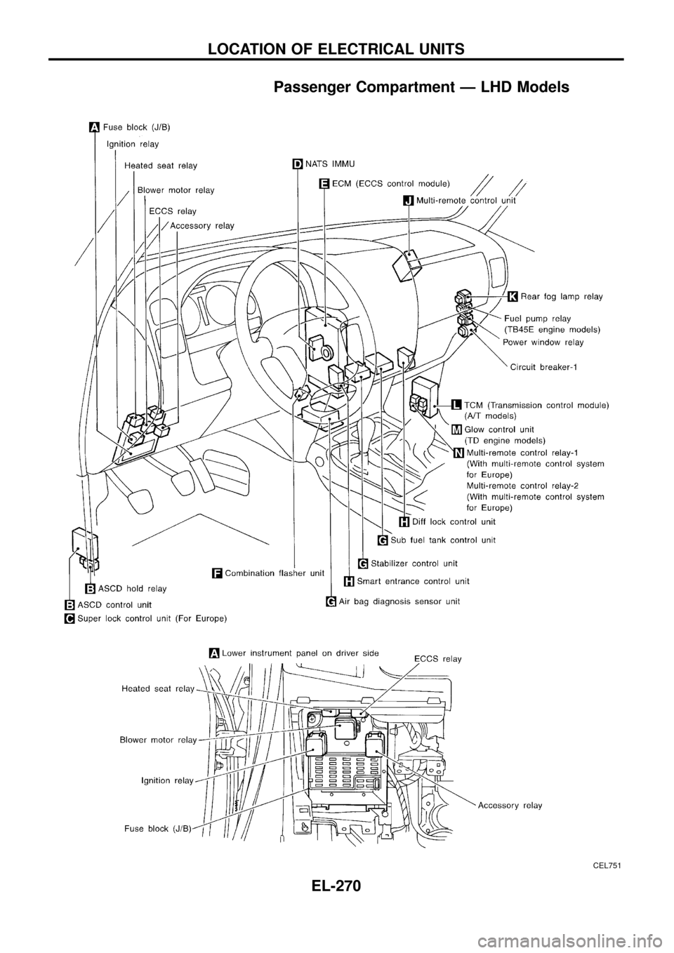
Passenger Compartment Ð LHD Models
CEL751
LOCATION OF ELECTRICAL UNITS
EL-270
Page 275 of 326
CEL752
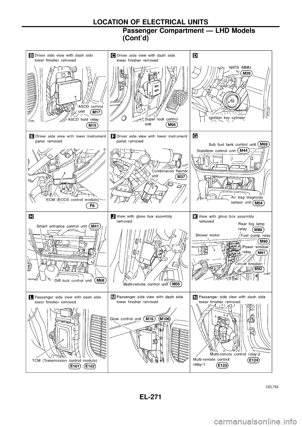
LOCATION OF ELECTRICAL UNITS
Passenger Compartment Ð LHD Models
(Cont'd)
EL-271
Page 276 of 326
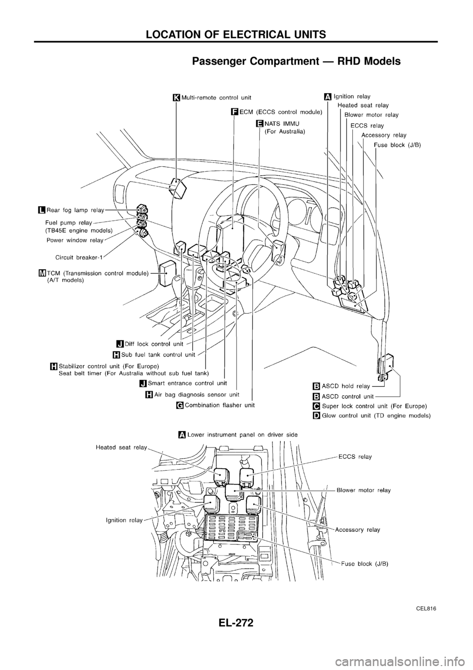
Passenger Compartment Ð RHD Models
CEL816
LOCATION OF ELECTRICAL UNITS
EL-272
Page 277 of 326
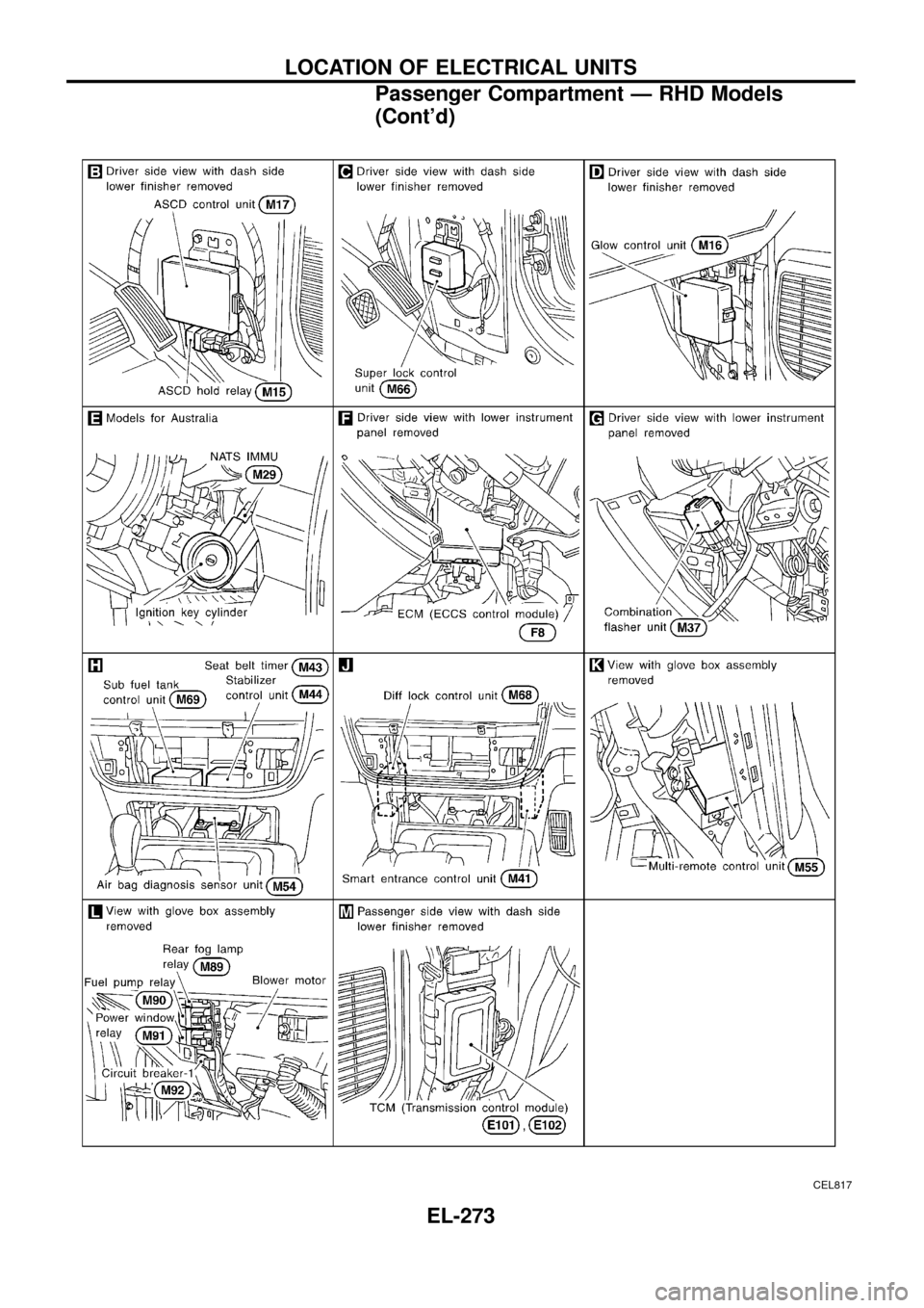
CEL817
LOCATION OF ELECTRICAL UNITS
Passenger Compartment Ð RHD Models
(Cont'd)
EL-273
Page 292 of 326
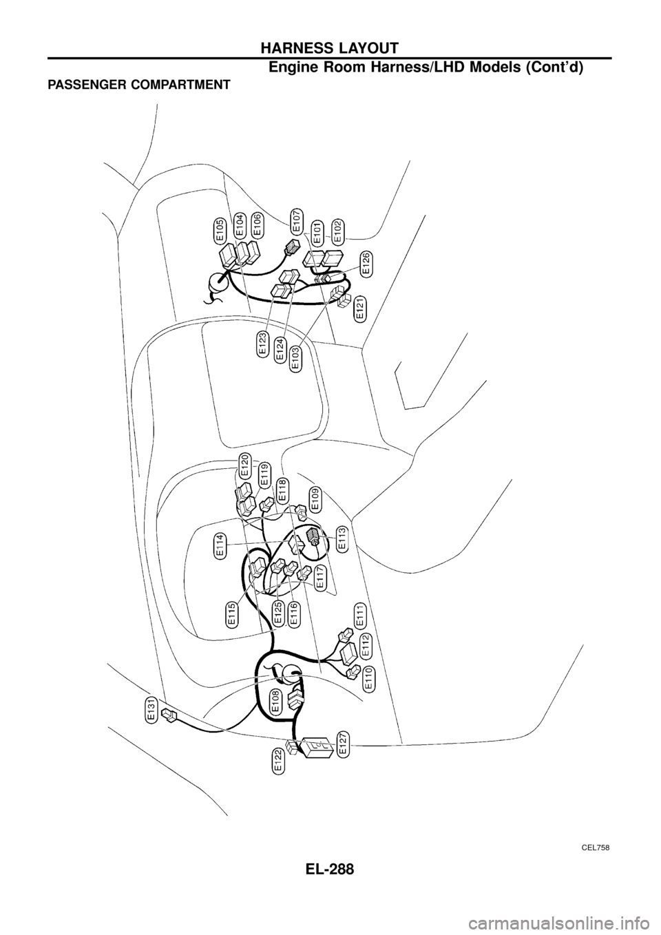
PASSENGER COMPARTMENT
CEL758
HARNESS LAYOUT
Engine Room Harness/LHD Models (Cont'd)
EL-288
Page 296 of 326
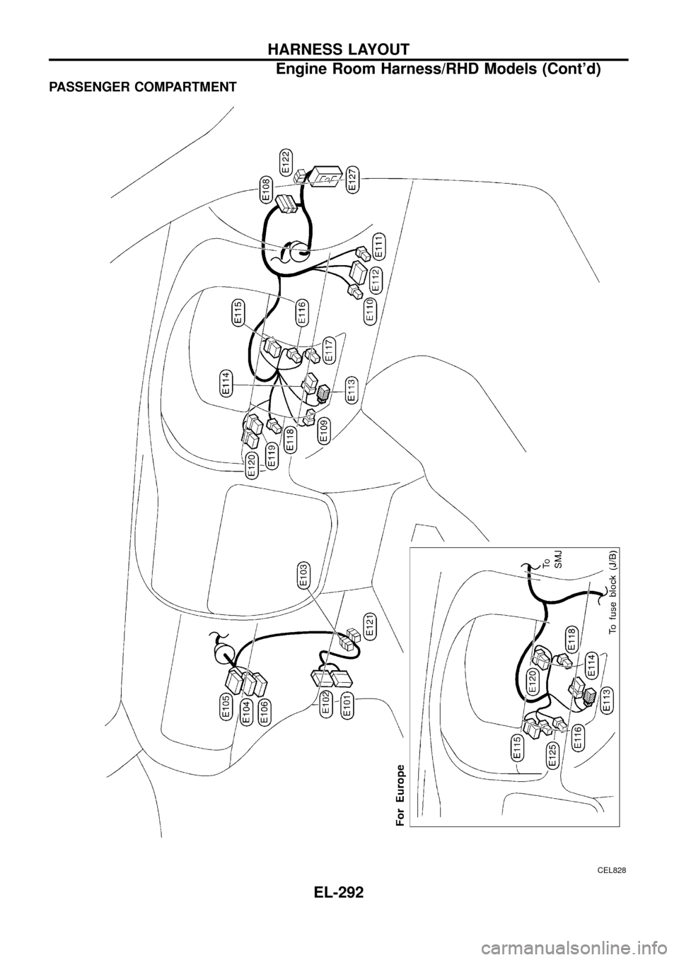
PASSENGER COMPARTMENT
CEL828
HARNESS LAYOUT
Engine Room Harness/RHD Models (Cont'd)
EL-292
Page 315 of 326
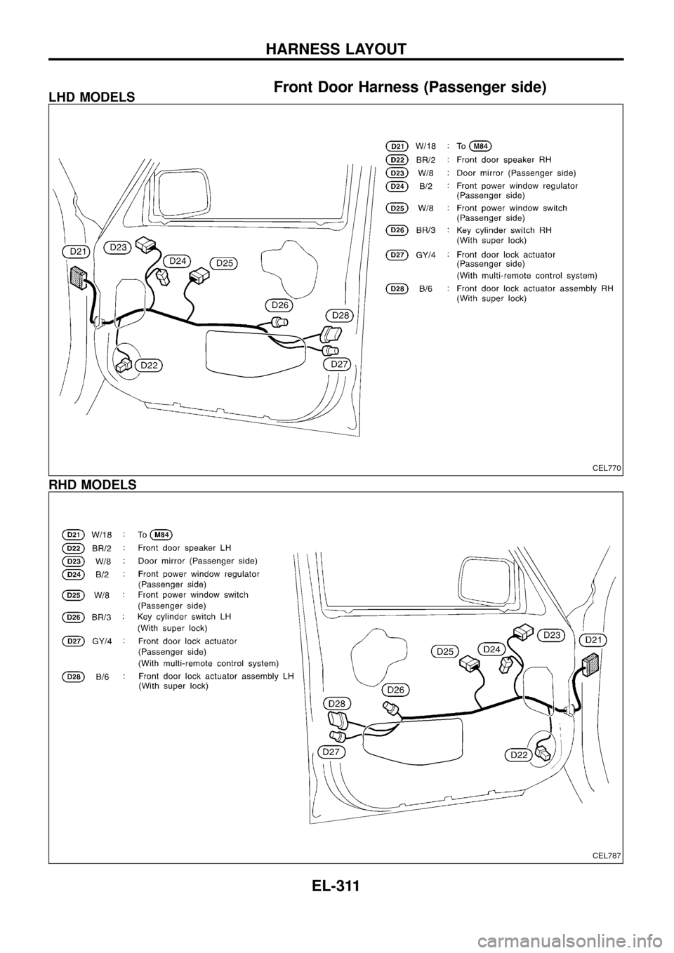
Front Door Harness (Passenger side)LHD MODELS
RHD MODELS
CEL770
CEL787
HARNESS LAYOUT
EL-311
Page 319 of 326
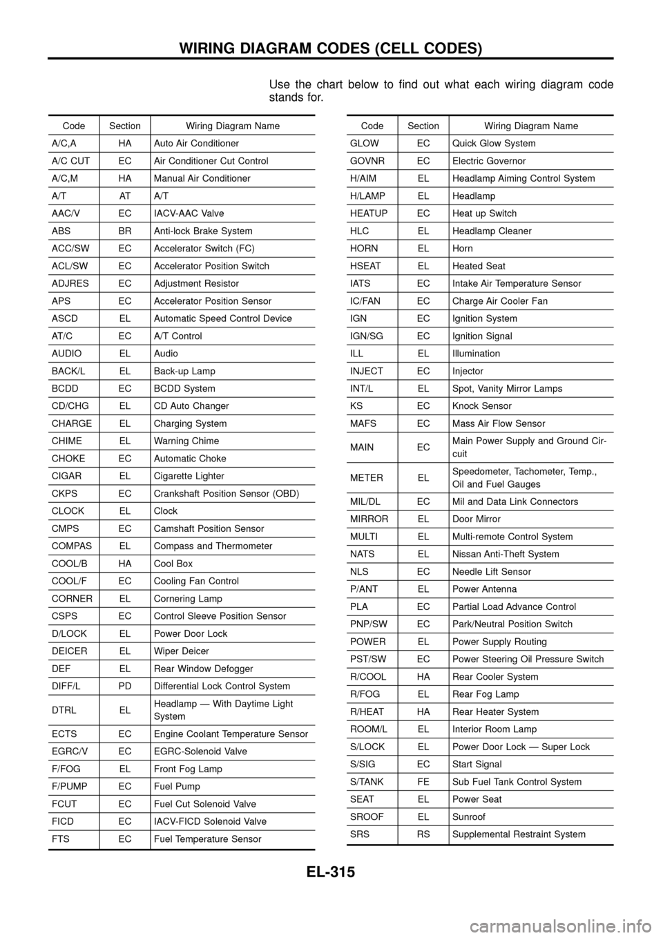
Use the chart below to ®nd out what each wiring diagram code
stands for.
Code Section Wiring Diagram Name
A/C,A HA Auto Air Conditioner
A/C CUT EC Air Conditioner Cut Control
A/C,M HA Manual Air Conditioner
A/T AT A/T
AAC/V EC IACV-AAC Valve
ABS BR Anti-lock Brake System
ACC/SW EC Accelerator Switch (FC)
ACL/SW EC Accelerator Position Switch
ADJRES EC Adjustment Resistor
APS EC Accelerator Position Sensor
ASCD EL Automatic Speed Control Device
AT/C EC A/T Control
AUDIO EL Audio
BACK/L EL Back-up Lamp
BCDD EC BCDD System
CD/CHG EL CD Auto Changer
CHARGE EL Charging System
CHIME EL Warning Chime
CHOKE EC Automatic Choke
CIGAR EL Cigarette Lighter
CKPS EC Crankshaft Position Sensor (OBD)
CLOCK EL Clock
CMPS EC Camshaft Position Sensor
COMPAS EL Compass and Thermometer
COOL/B HA Cool Box
COOL/F EC Cooling Fan Control
CORNER EL Cornering Lamp
CSPS EC Control Sleeve Position Sensor
D/LOCK EL Power Door Lock
DEICER EL Wiper Deicer
DEF EL Rear Window Defogger
DIFF/L PD Differential Lock Control System
DTRL ELHeadlamp Ð With Daytime Light
System
ECTS EC Engine Coolant Temperature Sensor
EGRC/V EC EGRC-Solenoid Valve
F/FOG EL Front Fog Lamp
F/PUMP EC Fuel Pump
FCUT EC Fuel Cut Solenoid Valve
FICD EC IACV-FICD Solenoid Valve
FTS EC Fuel Temperature SensorCode Section Wiring Diagram Name
GLOW EC Quick Glow System
GOVNR EC Electric Governor
H/AIM EL Headlamp Aiming Control System
H/LAMP EL Headlamp
HEATUP EC Heat up Switch
HLC EL Headlamp Cleaner
HORN EL Horn
HSEAT EL Heated Seat
IATS EC Intake Air Temperature Sensor
IC/FAN EC Charge Air Cooler Fan
IGN EC Ignition System
IGN/SG EC Ignition Signal
ILL EL Illumination
INJECT EC Injector
INT/L EL Spot, Vanity Mirror Lamps
KS EC Knock Sensor
MAFS EC Mass Air Flow Sensor
MAIN ECMain Power Supply and Ground Cir-
cuit
METER ELSpeedometer, Tachometer, Temp.,
Oil and Fuel Gauges
MIL/DL EC Mil and Data Link Connectors
MIRROR EL Door Mirror
MULTI EL Multi-remote Control System
NATS EL Nissan Anti-Theft System
NLS EC Needle Lift Sensor
P/ANT EL Power Antenna
PLA EC Partial Load Advance Control
PNP/SW EC Park/Neutral Position Switch
POWER EL Power Supply Routing
PST/SW EC Power Steering Oil Pressure Switch
R/COOL HA Rear Cooler System
R/FOG EL Rear Fog Lamp
R/HEAT HA Rear Heater System
ROOM/L EL Interior Room Lamp
S/LOCK EL Power Door Lock Ð Super Lock
S/SIG EC Start Signal
S/TANK FE Sub Fuel Tank Control System
SEAT EL Power Seat
SROOF EL Sunroof
SRS RS Supplemental Restraint System
WIRING DIAGRAM CODES (CELL CODES)
EL-315