PAGE 211 NISSAN PATROL 1998 Y61 / 5.G Electrical System Workshop Manual
[x] Cancel search | Manufacturer: NISSAN, Model Year: 1998, Model line: PATROL, Model: NISSAN PATROL 1998 Y61 / 5.GPages: 326, PDF Size: 11.36 MB
Page 241 of 326

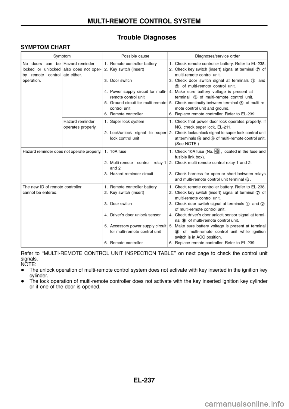
Trouble Diagnoses
SYMPTOM CHART
Symptom Possible cause Diagnoses/service order
No doors can be
locked or unlocked
by remote control
operation.Hazard reminder
also does not oper-
ate either.1. Remote controller battery
2. Key switch (insert)
3. Door switch
4. Power supply circuit for multi-
remote control unit
5. Ground circuit for multi-remote
control unit
6. Remote controller1. Check remote controller battery. Refer to EL-238.
2. Check key switch (insert) signal at terminalj
7of
multi-remote control unit.
3. Check door switch signal at terminalsj
1and
j
2of multi-remote control unit.
4. Make sure battery voltage is present at
terminalj
3of multi-remote control unit.
5. Check continuity between terminalj
5of multi-re-
mote control unit and ground.
6. Replace remote controller. Refer to EL-239.
Hazard reminder
operates properly.1. Super lock system
2. Lock/unlock signal to super
lock control unit1. Check that power door lock operates properly. If
NG, check super lock, EL-211.
2. Check lock/unlock signal to super lock control unit
at terminalsj
10andj11of multi-remote control unit.
(See NOTE.)
Hazard reminder does not operate properly. 1. 10A fuse
2. Multi-remote control relay-1
and 2
3. Hazard reminder circuit1. Check 10A fuse (No.
48, located in the fuse and
fusible link box).
2. Check multi-remote control relay-1 and 2.
3. Check harness for open or short between relays
and multi-remote control unit terminalj
12.
The new ID of remote controller
cannot be entered.1. Remote controller battery
2. Key switch (insert)
3. Door switch
4. Driver's door unlock sensor
5. Accessory power supply circuit
for multi-remote control unit
6. Remote controller1. Check remote controller battery. Refer to EL-238.
2. Check key switch (insert) signal at terminalj
7of
multi-remote control unit.
3. Check door switch signal at terminalsj
1andj2
of multi-remote control unit.
4. Check driver's door unlock sensor signal at termi-
nalj
6of multi-remote control unit.
5. Make sure battery voltage is present at terminal
j
8of multi-remote control unit while ignition
switch is in ACC position.
6. Replace remote controller. Refer to EL-239.
Refer to ``MULTI-REMOTE CONTROL UNIT INSPECTION TABLE'' on next page to check the control unit
signals.
NOTE:
+The unlock operation of multi-remote control system does not activate with key inserted in the ignition key
cylinder.
+The lock operation of multi-remote controller does not activate with the key inserted ignition key cylinder
or if one of the door is opened.
MULTI-REMOTE CONTROL SYSTEM
EL-237