reset NISSAN PATROL 1998 Y61 / 5.G Engine Control Workshop Manual
[x] Cancel search | Manufacturer: NISSAN, Model Year: 1998, Model line: PATROL, Model: NISSAN PATROL 1998 Y61 / 5.GPages: 192, PDF Size: 4.28 MB
Page 17 of 192

Fuel Injection System
SYSTEM DESCRIPTION
Three types of fuel injection control are provided to accommodate engine operating conditions; normal control,
idle control and start control. The ECM determines the appropriate fuel injection control. Under each control,
the amount of fuel injected is compensated to improve engine performance. The ECM performs duty control
on the electric governor (built into the fuel injection pump) according to sensor signals to compensate the
amount of fuel injected to the preset value.
START CONTROL
Input/output signal line
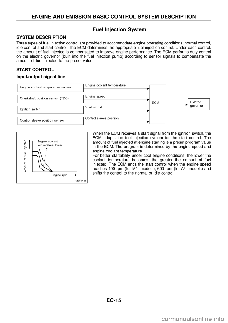
Engine coolant temperature sensorcEngine coolant temperature
ECM
cElectric
governorCrankshaft position sensor (TDC)cEngine speed
Ignition switch
cStart signal
Control sleeve position sensor
cControl sleeve position
When the ECM receives a start signal from the ignition switch, the
ECM adapts the fuel injection system for the start control. The
amount of fuel injected at engine starting is a preset program value
in the ECM. The program is determined by the engine speed and
engine coolant temperature.
For better startability under cool engine conditions, the lower the
coolant temperature becomes, the greater the amount of fuel
injected. The ECM ends the start control when the engine speed
reaches 400 rpm (for M/T models), 600 rpm (for A/T models) and
shifts the control to the normal or idle control.
SEF648S
ENGINE AND EMISSION BASIC CONTROL SYSTEM DESCRIPTION
EC-15
Page 43 of 192

REAL TIME DIAGNOSIS IN DATA MONITOR MODE
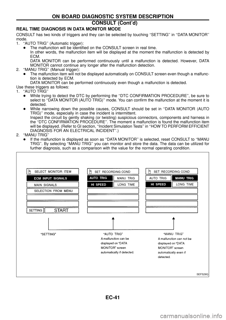
CONSULT has two kinds of triggers and they can be selected by touching ``SETTING'' in ``DATA MONITOR''
mode.
1. ``AUTO TRIG'' (Automatic trigger):
+The malfunction will be identi®ed on the CONSULT screen in real time.
In other words, the malfunction item will be displayed at the moment the malfunction is detected by
ECM.
DATA MONITOR can be performed continuously until a malfunction is detected. However, DATA
MONITOR cannot continue any longer after the malfunction detection.
2. ``MANU TRIG'' (Manual trigger):
+The malfunction item will not be displayed automatically on CONSULT screen even though a malfunc-
tion is detected by ECM.
DATA MONITOR can be performed continuously even though a malfunction is detected.
Use these triggers as follows:
1. ``AUTO TRIG''
+While trying to detect the DTC by performing the ``DTC CONFIRMATION PROCEDURE'', be sure to
select to ``DATA MONITOR (AUTO TRIG)'' mode. You can con®rm the malfunction at the moment it is
detected.
+While narrowing down the possible causes, CONSULT should be set in ``DATA MONITOR (AUTO
TRIG)'' mode, especially in case the incident is intermittent.
Inspect the circuit by gently shaking (or twisting) suspicious connectors, components and harness in
the ``DTC CONFIRMATION PROCEDURE''. The moment a malfunction is found the malfunction item
will be displayed. (Refer to GI section, ``Incident Simulation Tests'' in ``HOW TO PERFORM EFFICIENT
DIAGNOSIS FOR AN ELECTRICAL INCIDENT''.)
2. ``MANU TRIG''
+If the malfunction is displayed as soon as ``DATA MONITOR'' is selected, reset CONSULT to ``MANU
TRIG''. By selecting ``MANU TRIG'' you can monitor and store the data. The data can be utilized for
further diagnosis, such as a comparison with the value for the normal operating condition.
SEF529Q
ON BOARD DIAGNOSTIC SYSTEM DESCRIPTION
CONSULT (Cont'd)
EC-41