check engine NISSAN PATROL 1998 Y61 / 5.G Engine Mechanical Workshop Manual
[x] Cancel search | Manufacturer: NISSAN, Model Year: 1998, Model line: PATROL, Model: NISSAN PATROL 1998 Y61 / 5.GPages: 65, PDF Size: 2.4 MB
Page 1 of 65
ENGINE MECHANICAL
SECTION
EM
CONTENTS
PRECAUTIONS...............................................................1
Parts Requiring Angular Tightening .............................1
Liquid Gasket Application Procedure ..........................1
PREPARATION................................................................2
NOISE, VIBRATION AND HARSHNESS (NVH)
TROUBLESHOOTING.....................................................6
NVH Troubleshooting Chart Ð Engine Noise .............7
OUTER COMPONENT PARTS.......................................8
COMPRESSION PRESSURE........................................10
Measurement of Compression Pressure ...................10
OIL PAN.........................................................................13
Removal .....................................................................13
Installation ..................................................................14
TIMING BELT.................................................................15
Removal .....................................................................15
Inspection...................................................................17
Installation ..................................................................18
OIL SEAL REPLACEMENT..........................................20
TURBOCHARGER.........................................................23
Removal and Installation ...........................................23
Inspection...................................................................24CHARGE AIR COOLERS..............................................27
CYLINDER HEAD..........................................................28
Removal .....................................................................29
Disassembly...............................................................30
Inspection...................................................................31
Assembly ...................................................................37
Installation ..................................................................37
VALVE CLEARANCE....................................................40
Checking ....................................................................40
Adjusting ....................................................................41
ENGINE REMOVAL.......................................................43
Removal .....................................................................44
Installation ..................................................................44
CYLINDER BLOCK.......................................................45
Disassembly...............................................................46
Inspection...................................................................46
Assembly ...................................................................53
SERVICE DATA AND SPECIFICATIONS (SDS)..........56
General Speci®cations ...............................................56
Inspection and Adjustment ........................................56
EM
Page 9 of 65
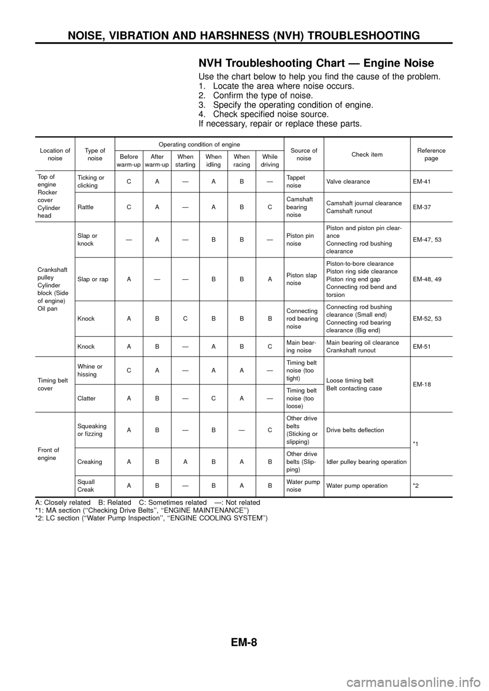
NVH Troubleshooting Chart Ð Engine Noise
Use the chart below to help you ®nd the cause of the problem.
1. Locate the area where noise occurs.
2. Con®rm the type of noise.
3. Specify the operating condition of engine.
4. Check speci®ed noise source.
If necessary, repair or replace these parts.
Location of
noiseType of
noiseOperating condition of engine
Source of
noiseCheck itemReference
page Before
warm-upAfter
warm-upWhen
startingWhen
idlingWhen
racingWhile
driving
To p o f
engine
Rocker
cover
Cylinder
headTicking or
clickingCAÐABÐTappet
noiseValve clearance EM-41
Rattle C A Ð A B CCamshaft
bearing
noiseCamshaft journal clearance
Camshaft runoutEM-37
Crankshaft
pulley
Cylinder
block (Side
of engine)
Oil panSlap or
knockÐAÐB BÐPiston pin
noisePiston and piston pin clear-
ance
Connecting rod bushing
clearanceEM-47, 53
Slap or rap A Ð Ð B B APiston slap
noisePiston-to-bore clearance
Piston ring side clearance
Piston ring end gap
Connecting rod bend and
torsionEM-48, 49
Knock A B C B B BConnecting
rod bearing
noiseConnecting rod bushing
clearance (Small end)
Connecting rod bearing
clearance (Big end)EM-52, 53
Knock A B Ð A B CMain bear-
ing noiseMain bearing oil clearance
Crankshaft runoutEM-51
Timing belt
coverWhine or
hissingCAÐAAÐTiming belt
noise (too
tight)
Loose timing belt
Belt contacting caseEM-18
Clatter A B Ð C A ÐTiming belt
noise (too
loose)
Front of
engineSqueaking
or ®zzingABÐBÐCOther drive
belts
(Sticking or
slipping)Drive belts de¯ection
*1
CreakingABABABOther drive
belts (Slip-
ping)Idler pulley bearing operation
Squall
CreakABÐBABWater pump
noiseWater pump operation *2
A: Closely related B: Related C: Sometimes related Ð: Not related
*1: MA section (``Checking Drive Belts'', ``ENGINE MAINTENANCE'')
*2: LC section (``Water Pump Inspection'', ``ENGINE COOLING SYSTEM'')
NOISE, VIBRATION AND HARSHNESS (NVH) TROUBLESHOOTING
EM-8
Page 19 of 65
Inspection
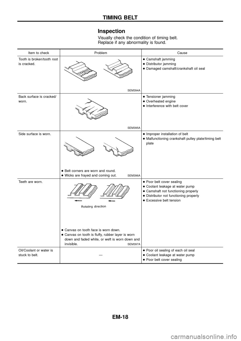
Visually check the condition of timing belt.
Replace if any abnormality is found.
Item to check Problem Cause
Tooth is broken/tooth root
is cracked.
SEM394A
+Camshaft jamming
+Distributor jamming
+Damaged camshaft/crankshaft oil seal
Back surface is cracked/
worn.
SEM395A
+Tensioner jamming
+Overheated engine
+Interference with belt cover
Side surface is worn.
+Belt corners are worn and round.
+Wicks are frayed and coming out.
SEM396A
+Improper installation of belt
+Malfunctioning crankshaft pulley plate/timing belt
plate
Teeth are worn.
+Canvas on tooth face is worn down.
+Canvas on tooth is ¯uffy, rubber layer is worn
down and faded white, or weft is worn down and
invisible.
SEM397A
+Poor belt cover sealing
+Coolant leakage at water pump
+Camshaft not functioning properly
+Distributor not functioning properly
+Excessive belt tension
Oil/Coolant or water is
stuck to belt. Ð+Poor oil sealing of each oil seal
+Coolant leakage at water pump
+Poor belt cover sealing
TIMING BELT
EM-18
Page 33 of 65
Inspection
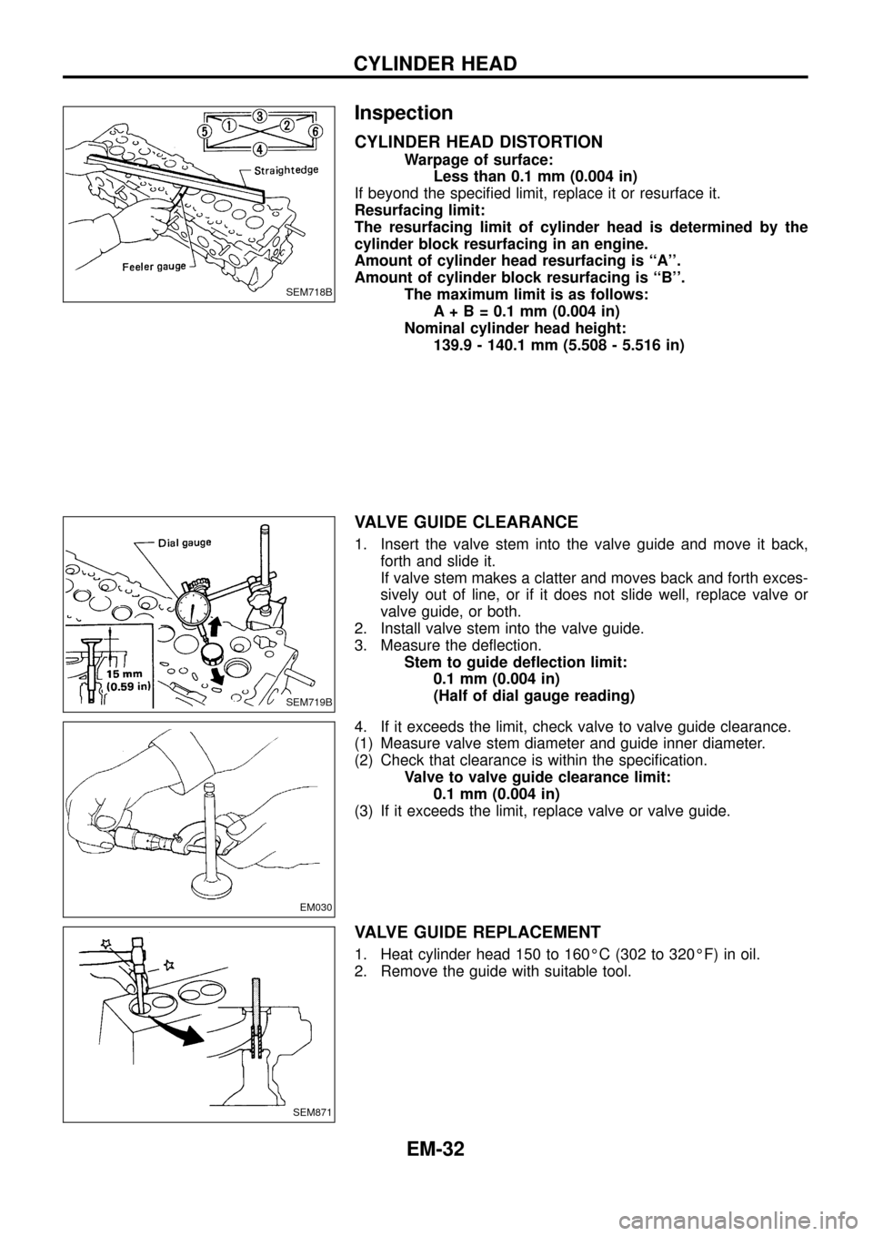
CYLINDER HEAD DISTORTION
Warpage of surface:
Less than 0.1 mm (0.004 in)
If beyond the speci®ed limit, replace it or resurface it.
Resurfacing limit:
The resurfacing limit of cylinder head is determined by the
cylinder block resurfacing in an engine.
Amount of cylinder head resurfacing is ``A''.
Amount of cylinder block resurfacing is ``B''.
The maximum limit is as follows:
A + B = 0.1 mm (0.004 in)
Nominal cylinder head height:
139.9 - 140.1 mm (5.508 - 5.516 in)
VALVE GUIDE CLEARANCE
1. Insert the valve stem into the valve guide and move it back,
forth and slide it.
If valve stem makes a clatter and moves back and forth exces-
sively out of line, or if it does not slide well, replace valve or
valve guide, or both.
2. Install valve stem into the valve guide.
3. Measure the de¯ection.
Stem to guide de¯ection limit:
0.1 mm (0.004 in)
(Half of dial gauge reading)
4. If it exceeds the limit, check valve to valve guide clearance.
(1) Measure valve stem diameter and guide inner diameter.
(2) Check that clearance is within the speci®cation.
Valve to valve guide clearance limit:
0.1 mm (0.004 in)
(3) If it exceeds the limit, replace valve or valve guide.
VALVE GUIDE REPLACEMENT
1. Heat cylinder head 150 to 160ÉC (302 to 320ÉF) in oil.
2. Remove the guide with suitable tool.
SEM718B
SEM719B
EM030
SEM871
CYLINDER HEAD
EM-32
Page 37 of 65
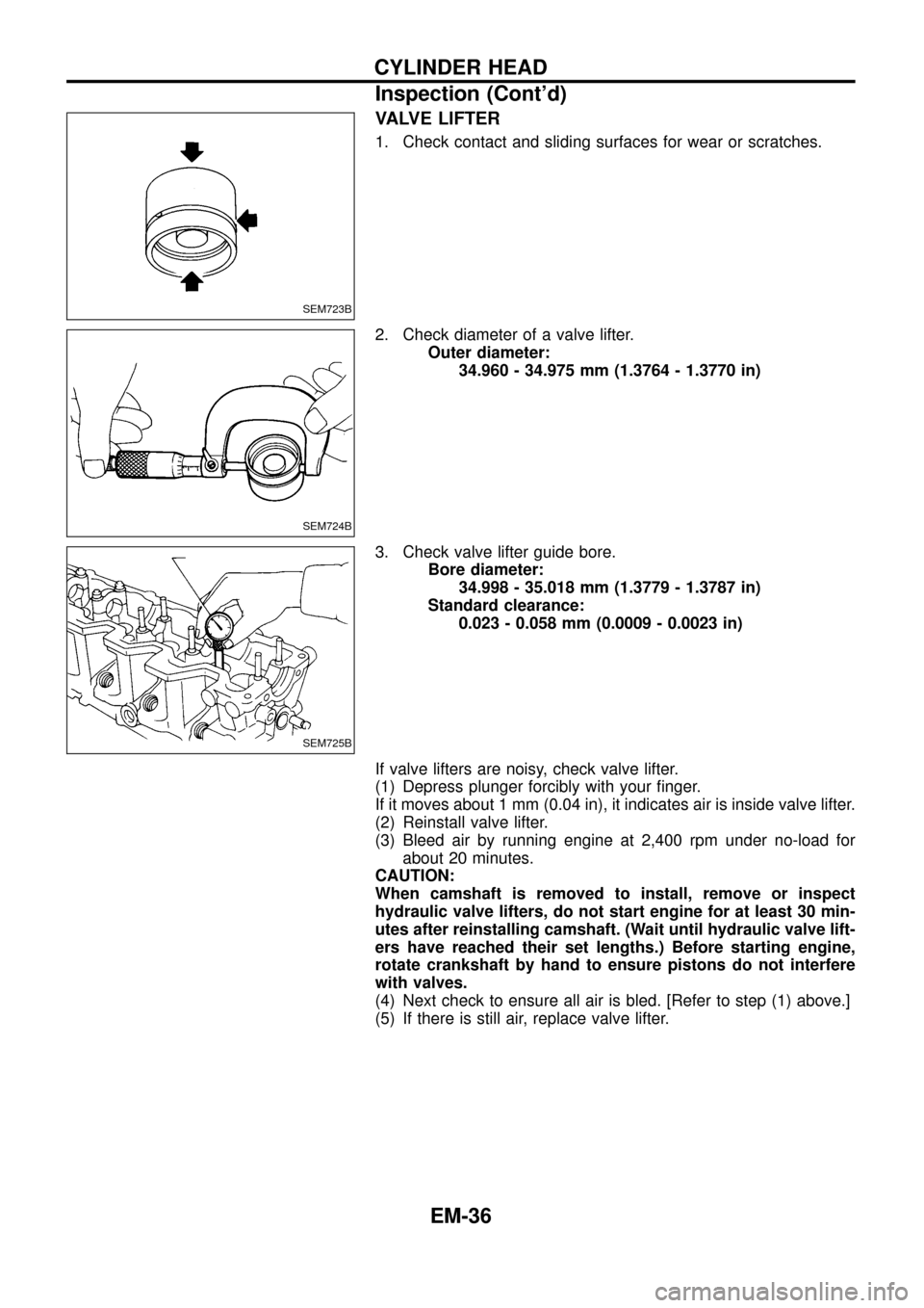
VALVE LIFTER
1. Check contact and sliding surfaces for wear or scratches.
2. Check diameter of a valve lifter.
Outer diameter:
34.960 - 34.975 mm (1.3764 - 1.3770 in)
3. Check valve lifter guide bore.
Bore diameter:
34.998 - 35.018 mm (1.3779 - 1.3787 in)
Standard clearance:
0.023 - 0.058 mm (0.0009 - 0.0023 in)
If valve lifters are noisy, check valve lifter.
(1) Depress plunger forcibly with your ®nger.
If it moves about 1 mm (0.04 in), it indicates air is inside valve lifter.
(2) Reinstall valve lifter.
(3) Bleed air by running engine at 2,400 rpm under no-load for
about 20 minutes.
CAUTION:
When camshaft is removed to install, remove or inspect
hydraulic valve lifters, do not start engine for at least 30 min-
utes after reinstalling camshaft. (Wait until hydraulic valve lift-
ers have reached their set lengths.) Before starting engine,
rotate crankshaft by hand to ensure pistons do not interfere
with valves.
(4) Next check to ensure all air is bled. [Refer to step (1) above.]
(5) If there is still air, replace valve lifter.
SEM723B
SEM724B
SEM725B
CYLINDER HEAD
Inspection (Cont'd)
EM-36
Page 39 of 65
Assembly
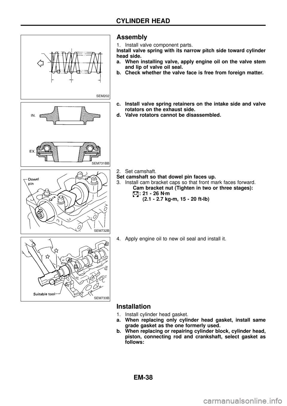
1. Install valve component parts.
Install valve spring with its narrow pitch side toward cylinder
head side.
a. When installing valve, apply engine oil on the valve stem
and lip of valve oil seal.
b. Check whether the valve face is free from foreign matter.
c. Install valve spring retainers on the intake side and valve
rotators on the exhaust side.
d. Valve rotators cannot be disassembled.
2. Set camshaft.
Set camshaft so that dowel pin faces up.
3. Install cam bracket caps so that front mark faces forward.
Cam bracket nut (Tighten in two or three stages):
:21-26Nzm
(2.1 - 2.7 kg-m, 15 - 20 ft-lb)
4. Apply engine oil to new oil seal and install it.
Installation
1. Install cylinder head gasket.
a. When replacing only cylinder head gasket, install same
grade gasket as the one formerly used.
b. When replacing or repairing cylinder block, cylinder head,
piston, connecting rod and crankshaft, select gasket as
follows:
SEM202
SEM731BB
SEM732B
SEM733B
CYLINDER HEAD
EM-38
Page 42 of 65
Checking
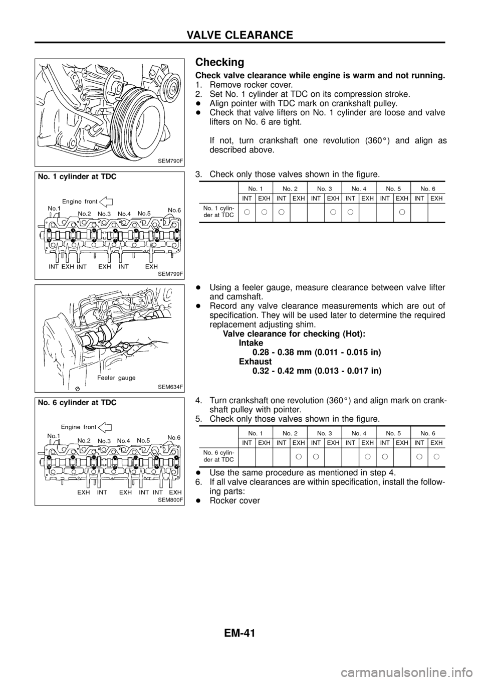
Check valve clearance while engine is warm and not running.
1. Remove rocker cover.
2. Set No. 1 cylinder at TDC on its compression stroke.
+Align pointer with TDC mark on crankshaft pulley.
+Check that valve lifters on No. 1 cylinder are loose and valve
lifters on No. 6 are tight.
If not, turn crankshaft one revolution (360É) and align as
described above.
3. Check only those valves shown in the ®gure.
No. 1 No. 2 No. 3 No. 4 No. 5 No. 6
INT EXH INT EXH INT EXH INT EXH INT EXH INT EXH
No. 1 cylin-
der at TDCjjj jj j
+Using a feeler gauge, measure clearance between valve lifter
and camshaft.
+Record any valve clearance measurements which are out of
speci®cation. They will be used later to determine the required
replacement adjusting shim.
Valve clearance for checking (Hot):
Intake
0.28 - 0.38 mm (0.011 - 0.015 in)
Exhaust
0.32 - 0.42 mm (0.013 - 0.017 in)
4. Turn crankshaft one revolution (360É) and align mark on crank-
shaft pulley with pointer.
5. Check only those valves shown in the ®gure.
No. 1 No. 2 No. 3 No. 4 No. 5 No. 6
INT EXH INT EXH INT EXH INT EXH INT EXH INT EXH
No. 6 cylin-
der at TDCjj jj jj
+Use the same procedure as mentioned in step 4.
6. If all valve clearances are within speci®cation, install the follow-
ing parts:
+Rocker cover
SEM790F
SEM799F
SEM634F
SEM800F
VALVE CLEARANCE
EM-41