engine coolant NISSAN PATROL 1998 Y61 / 5.G Engine Mechanical Workshop Manual
[x] Cancel search | Manufacturer: NISSAN, Model Year: 1998, Model line: PATROL, Model: NISSAN PATROL 1998 Y61 / 5.GPages: 65, PDF Size: 2.4 MB
Page 2 of 65
Parts Requiring Angular Tightening
+Some important engine parts are tightened using an angular-
tightening method rather than a torque setting method.
+If these parts are tightened using a torque setting method, dis-
persal of the tightening force (axial bolt force) will be two or
three times that of the dispersal produced by using the correct
angular-tightening method.
+Although the torque setting values (described in this manual)
are equivalent to those used when bolts and nuts are tightened
with an angular-tightening method, they should be used for
reference only.
+To assure the satisfactory maintenance of the engine, bolts and
nuts must be tightened using an angular-tightening method.
+Before tightening the bolts and nuts, ensure that the thread and
seating surfaces are clean and then coated with engine oil.
+The bolts and nuts which require the angular-tightening method
are cylinder head bolts.
Liquid Gasket Application Procedure
a. Before applying liquid gasket, use a scraper to remove all
traces of old liquid gasket from mating surface.
b. Apply a continuous bead of liquid gasket to mating sur-
faces. (Use Genuine Liquid Gasket or equivalent.)
+Be sure liquid gasket is speci®ed width (for oil pan) 3.5
to 4.5 mm (0.138 to 0.177 in) for gasoline engine.
+Be sure liquid gasket is 2.0 to 3.0 mm (0.079 to 0.118
in) wide in areas except oil pan for TB and RD series
engines and 2.5 to 3.5 mm (0.098 to 0.138 in) for TD
series engine.
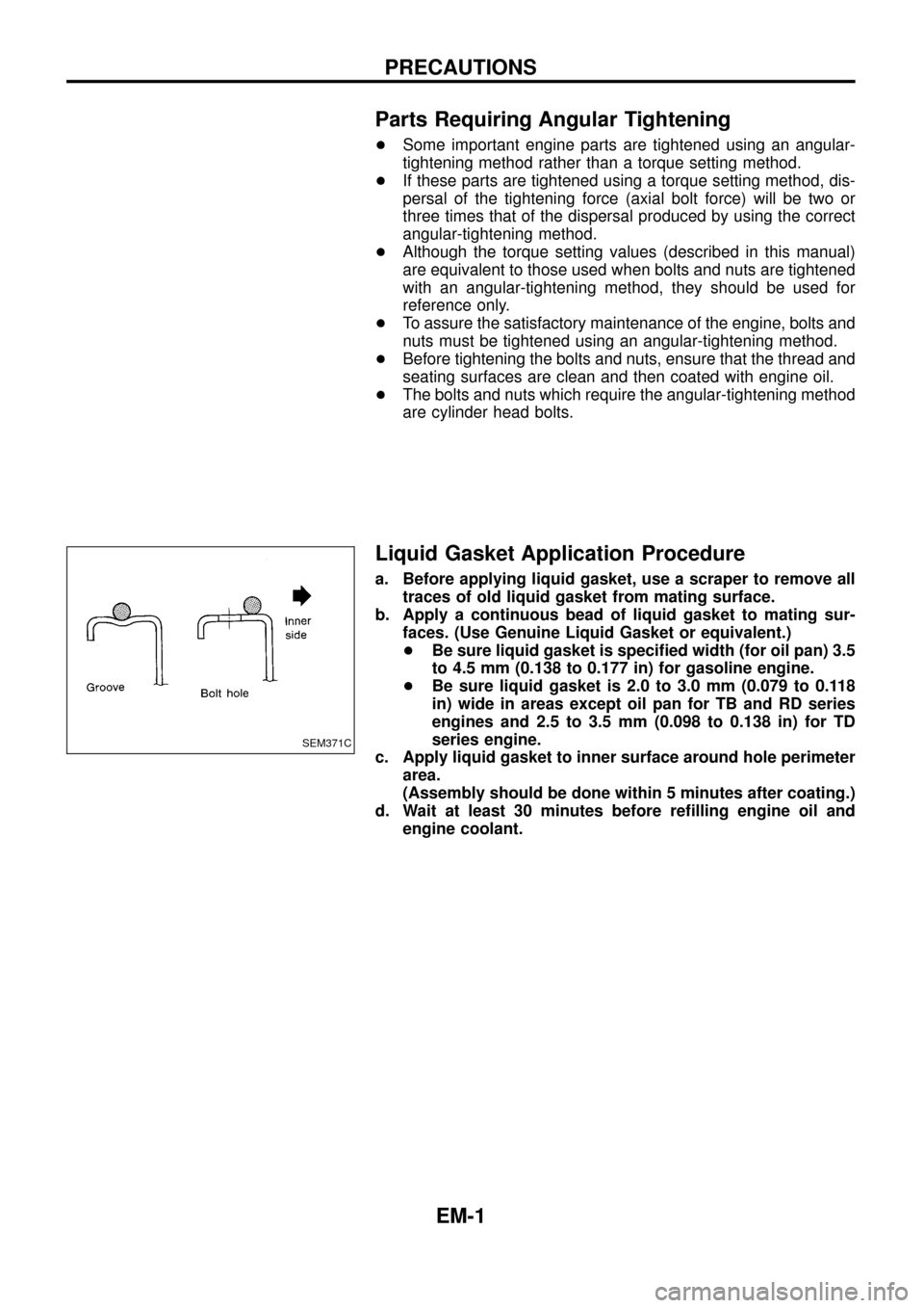
c. Apply liquid gasket to inner surface around hole perimeter
area.
(Assembly should be done within 5 minutes after coating.)
d. Wait at least 30 minutes before re®lling engine oil and
engine coolant.
SEM371C
PRECAUTIONS
EM-1
Page 19 of 65
Inspection
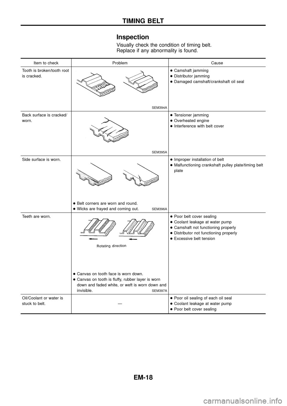
Visually check the condition of timing belt.
Replace if any abnormality is found.
Item to check Problem Cause
Tooth is broken/tooth root
is cracked.
SEM394A
+Camshaft jamming
+Distributor jamming
+Damaged camshaft/crankshaft oil seal
Back surface is cracked/
worn.
SEM395A
+Tensioner jamming
+Overheated engine
+Interference with belt cover
Side surface is worn.
+Belt corners are worn and round.
+Wicks are frayed and coming out.
SEM396A
+Improper installation of belt
+Malfunctioning crankshaft pulley plate/timing belt
plate
Teeth are worn.
+Canvas on tooth face is worn down.
+Canvas on tooth is ¯uffy, rubber layer is worn
down and faded white, or weft is worn down and
invisible.
SEM397A
+Poor belt cover sealing
+Coolant leakage at water pump
+Camshaft not functioning properly
+Distributor not functioning properly
+Excessive belt tension
Oil/Coolant or water is
stuck to belt. Ð+Poor oil sealing of each oil seal
+Coolant leakage at water pump
+Poor belt cover sealing
TIMING BELT
EM-18
Page 25 of 65
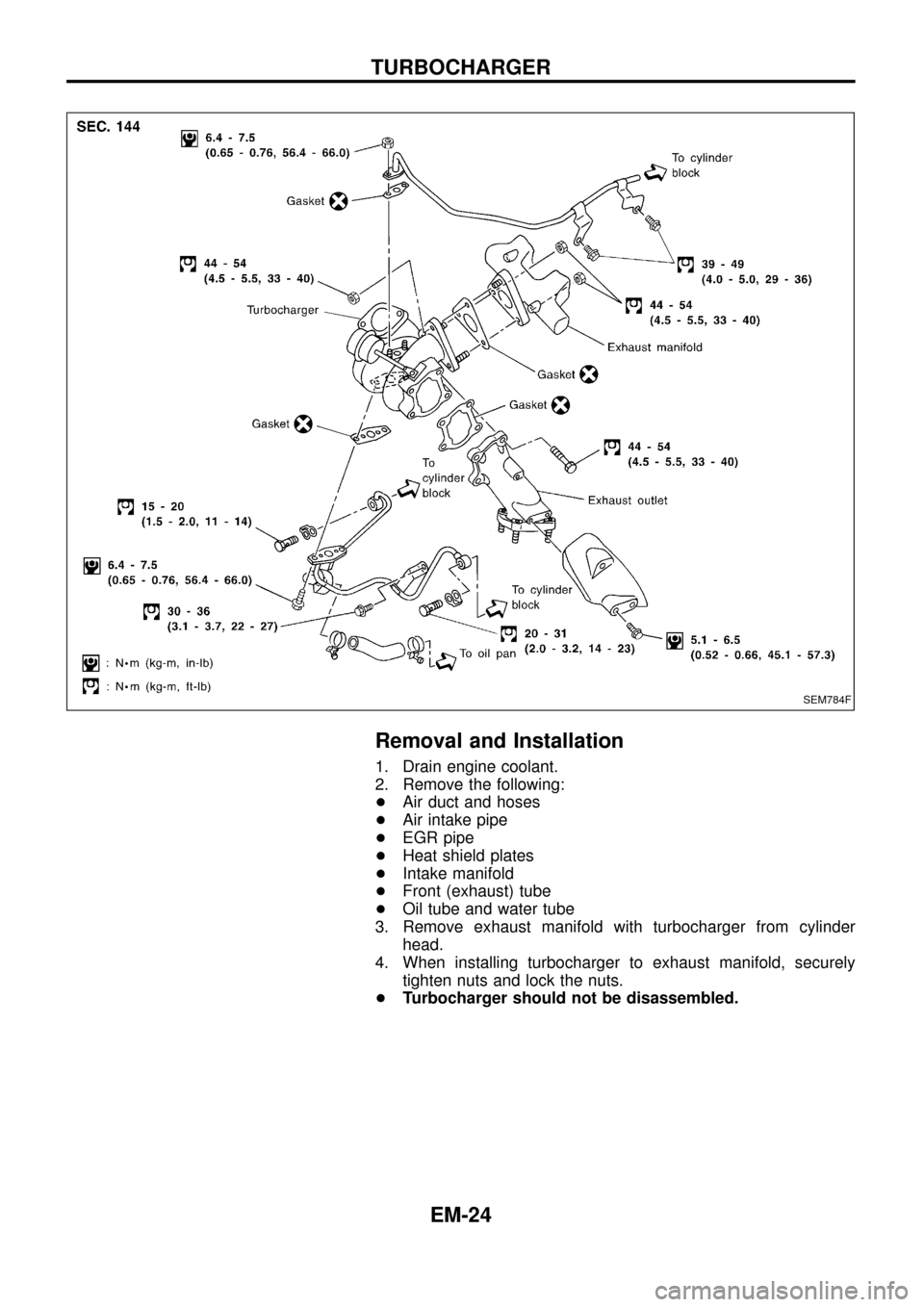
Removal and Installation
1. Drain engine coolant.
2. Remove the following:
+Air duct and hoses
+Air intake pipe
+EGR pipe
+Heat shield plates
+Intake manifold
+Front (exhaust) tube
+Oil tube and water tube
3. Remove exhaust manifold with turbocharger from cylinder
head.
4. When installing turbocharger to exhaust manifold, securely
tighten nuts and lock the nuts.
+Turbocharger should not be disassembled.
SEM784F
TURBOCHARGER
EM-24
Page 31 of 65
CAUTION:
+When installing sliding parts such as camshaft and oil
seal, be sure to apply new engine oil on their sliding sur-
faces.
+When tightening cylinder head bolts, apply new engine oil
to thread portions and seat surfaces of bolts.
Removal
1. Remove charge air cooler assembly.
2. Set No. 1 cylinder at BDC on its expansion stroke.
3. Drain engine coolant from drain plugs on cylinder block and
radiator.
4. Remove air cleaner and/or air duct.
5. Remove timing belt.
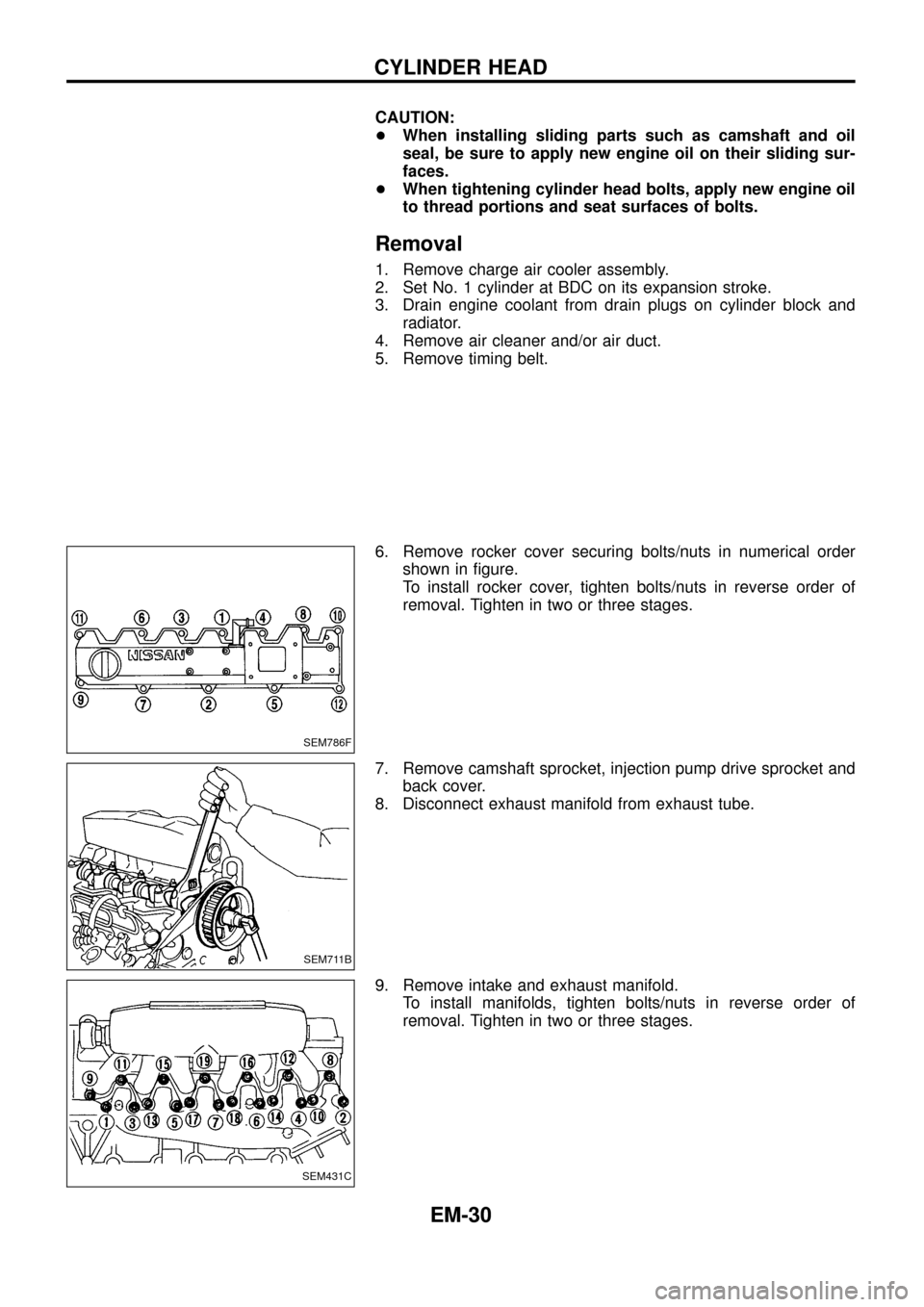
6. Remove rocker cover securing bolts/nuts in numerical order
shown in ®gure.
To install rocker cover, tighten bolts/nuts in reverse order of
removal. Tighten in two or three stages.
7. Remove camshaft sprocket, injection pump drive sprocket and
back cover.
8. Disconnect exhaust manifold from exhaust tube.
9. Remove intake and exhaust manifold.
To install manifolds, tighten bolts/nuts in reverse order of
removal. Tighten in two or three stages.
SEM786F
SEM711B
SEM431C
CYLINDER HEAD
EM-30
Page 46 of 65
Removal
1. Remove engine, transmission and transfer's undercovers, oil
pan guard and hood.
2. Drain engine coolant.
3. Remove charge air cooler assembly.
4. Remove vacuum hoses, fuel tubes, harnesses, and connectors
and so on.
5. Remove radiator assembly.
6. Remove drive belts.
7. Remove power steering oil pump, alternator and air conditioner
compressor.
8. Remove starter motor assembly.
9. Remove front exhaust tube.
10. Remove transmission from vehicle.
Refer to MT section.
11. Hoist engine with engine slingers and remove engine mounting
bolts from both sides.
12. Remove engine from vehicle.
Installation
+Install in reverse order of removal.
ENGINE REMOVAL
EM-45
Page 48 of 65
CAUTION:
+When installing sliding parts such as bearings and
pistons, apply engine oil to the sliding surfaces.
+Place removed parts, such as bearings and bearing caps,
in their proper order and direction.
+When installing connecting rod bolts and main bearing cap
bolts, apply new engine oil to threads and seating surfaces
of nuts.
+Do not allow any magnetic materials to contact the ring
gear teeth of drive plate.
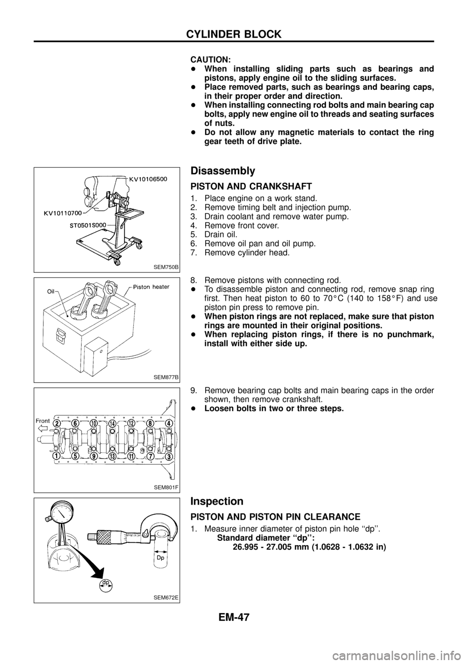
Disassembly
PISTON AND CRANKSHAFT
1. Place engine on a work stand.
2. Remove timing belt and injection pump.
3. Drain coolant and remove water pump.
4. Remove front cover.
5. Drain oil.
6. Remove oil pan and oil pump.
7. Remove cylinder head.
8. Remove pistons with connecting rod.
+To disassemble piston and connecting rod, remove snap ring
®rst. Then heat piston to 60 to 70ÉC (140 to 158ÉF) and use
piston pin press to remove pin.
+When piston rings are not replaced, make sure that piston
rings are mounted in their original positions.
+When replacing piston rings, if there is no punchmark,
install with either side up.
9. Remove bearing cap bolts and main bearing caps in the order
shown, then remove crankshaft.
+Loosen bolts in two or three steps.
Inspection
PISTON AND PISTON PIN CLEARANCE
1. Measure inner diameter of piston pin hole ``dp''.
Standard diameter ``dp'':
26.995 - 27.005 mm (1.0628 - 1.0632 in)
SEM750B
SEM877B
SEM801F
SEM672E
CYLINDER BLOCK
EM-47