torque NISSAN PATROL 1998 Y61 / 5.G Engine Mechanical Workshop Manual
[x] Cancel search | Manufacturer: NISSAN, Model Year: 1998, Model line: PATROL, Model: NISSAN PATROL 1998 Y61 / 5.GPages: 65, PDF Size: 2.4 MB
Page 2 of 65

Parts Requiring Angular Tightening
+Some important engine parts are tightened using an angular-
tightening method rather than a torque setting method.
+If these parts are tightened using a torque setting method, dis-
persal of the tightening force (axial bolt force) will be two or
three times that of the dispersal produced by using the correct
angular-tightening method.
+Although the torque setting values (described in this manual)
are equivalent to those used when bolts and nuts are tightened
with an angular-tightening method, they should be used for
reference only.
+To assure the satisfactory maintenance of the engine, bolts and
nuts must be tightened using an angular-tightening method.
+Before tightening the bolts and nuts, ensure that the thread and
seating surfaces are clean and then coated with engine oil.
+The bolts and nuts which require the angular-tightening method
are cylinder head bolts.
Liquid Gasket Application Procedure
a. Before applying liquid gasket, use a scraper to remove all
traces of old liquid gasket from mating surface.
b. Apply a continuous bead of liquid gasket to mating sur-
faces. (Use Genuine Liquid Gasket or equivalent.)
+Be sure liquid gasket is speci®ed width (for oil pan) 3.5
to 4.5 mm (0.138 to 0.177 in) for gasoline engine.
+Be sure liquid gasket is 2.0 to 3.0 mm (0.079 to 0.118
in) wide in areas except oil pan for TB and RD series
engines and 2.5 to 3.5 mm (0.098 to 0.138 in) for TD
series engine.
c. Apply liquid gasket to inner surface around hole perimeter
area.
(Assembly should be done within 5 minutes after coating.)
d. Wait at least 30 minutes before re®lling engine oil and
engine coolant.
SEM371C
PRECAUTIONS
EM-1
Page 41 of 65

2. Install cylinder head.
(1) Make sure that No. 1 cylinder is at Bottom Dead Center.
(2) Make sure that No. 1 cam of camshaft is at BDC on its expan-
sion stroke.
(3) Tighten cylinder head bolts to the speci®ed torque in the
sequence as follows:
+Tightening procedure.
M12 bolt
1st Tighten all bolts to 29 Nzm (3.0 kg-m, 22 ft-lb).
2nd Tighten all bolts to 113 Nzm (11.5 kg-m, 83 ft-lb).
3rd Loosen all bolts completely.
4th Tighten all bolts to 29 Nzm (3.0 kg-m, 22 ft-lb).
5th Tighten all bolts to 108 to 118 Nzm (11 to 12 kg-m, 80 to
87 ft-lb) or if you have an angle wrench, turn all bolts 89
to 92 degrees clockwise.
M8 bolt
16-21Nzm (1.6 - 2.1 kg-m, 12 - 15 ft-lb)
3. Install front back cover and camshaft pulley.
Front back cover:
:3-5Nzm
(0.3 - 0.5 kg-m, 26 - 43 in-lb)
Camshaft pulley:
: 123 - 132 Nzm
(12.5 - 13.5 kg-m, 90 - 98 ft-lb)
4. Install timing belt. Refer to ``Replacing Timing Belt'' in section
MA.
5. Install rocker cover. Refer to EM-30.
Apply sealant to rocker cover gasket as shown.
Do not apply too much sealant.
6. Install intake and exhaust manifold. Refer to EM-30.
SEM732B
SEM737BA
SEM711B
SEM738B
CYLINDER HEAD
Installation (Cont'd)
EM-40
Page 53 of 65

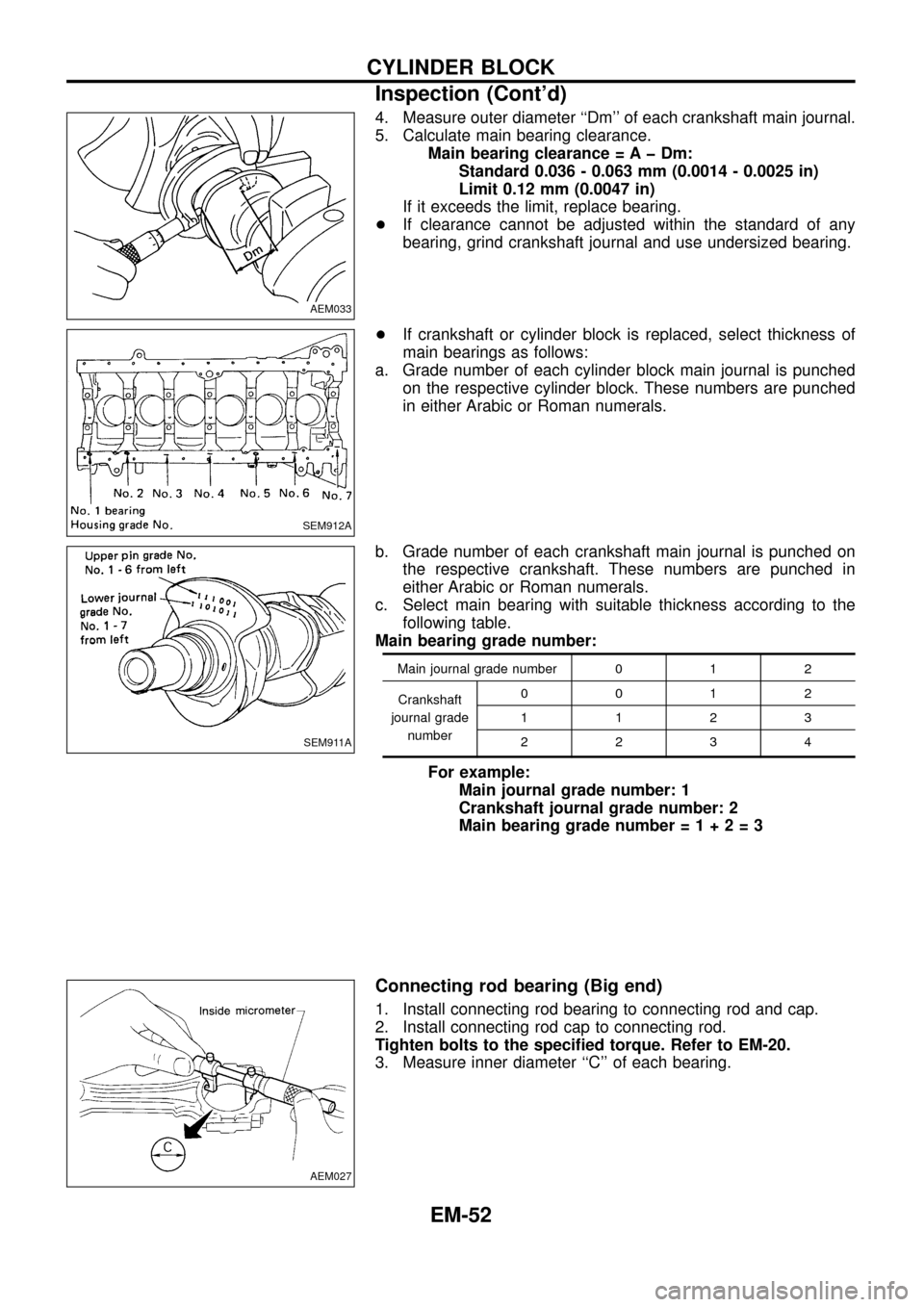
4. Measure outer diameter ``Dm'' of each crankshaft main journal.
5. Calculate main bearing clearance.
Main bearing clearance = A þ Dm:
Standard 0.036 - 0.063 mm (0.0014 - 0.0025 in)
Limit 0.12 mm (0.0047 in)
If it exceeds the limit, replace bearing.
+If clearance cannot be adjusted within the standard of any
bearing, grind crankshaft journal and use undersized bearing.
+If crankshaft or cylinder block is replaced, select thickness of
main bearings as follows:
a. Grade number of each cylinder block main journal is punched
on the respective cylinder block. These numbers are punched
in either Arabic or Roman numerals.
b. Grade number of each crankshaft main journal is punched on
the respective crankshaft. These numbers are punched in
either Arabic or Roman numerals.
c. Select main bearing with suitable thickness according to the
following table.
Main bearing grade number:
Main journal grade number 0 1 2
Crankshaft
journal grade
number0012
1123
2234
For example:
Main journal grade number: 1
Crankshaft journal grade number: 2
Main bearing grade number=1+2=3
Connecting rod bearing (Big end)
1. Install connecting rod bearing to connecting rod and cap.
2. Install connecting rod cap to connecting rod.
Tighten bolts to the speci®ed torque. Refer to EM-20.
3. Measure inner diameter ``C'' of each bearing.
AEM033
SEM912A
SEM911A
AEM027
CYLINDER BLOCK
Inspection (Cont'd)
EM-52
Page 56 of 65

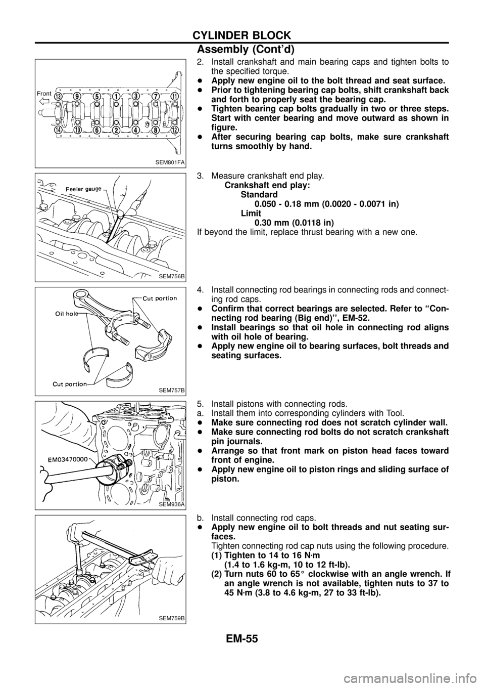
2. Install crankshaft and main bearing caps and tighten bolts to
the speci®ed torque.
+Apply new engine oil to the bolt thread and seat surface.
+Prior to tightening bearing cap bolts, shift crankshaft back
and forth to properly seat the bearing cap.
+Tighten bearing cap bolts gradually in two or three steps.
Start with center bearing and move outward as shown in
®gure.
+After securing bearing cap bolts, make sure crankshaft
turns smoothly by hand.
3. Measure crankshaft end play.
Crankshaft end play:
Standard
0.050 - 0.18 mm (0.0020 - 0.0071 in)
Limit
0.30 mm (0.0118 in)
If beyond the limit, replace thrust bearing with a new one.
4. Install connecting rod bearings in connecting rods and connect-
ing rod caps.
+Con®rm that correct bearings are selected. Refer to ``Con-
necting rod bearing (Big end)'', EM-52.
+Install bearings so that oil hole in connecting rod aligns
with oil hole of bearing.
+Apply new engine oil to bearing surfaces, bolt threads and
seating surfaces.
5. Install pistons with connecting rods.
a. Install them into corresponding cylinders with Tool.
+Make sure connecting rod does not scratch cylinder wall.
+Make sure connecting rod bolts do not scratch crankshaft
pin journals.
+Arrange so that front mark on piston head faces toward
front of engine.
+Apply new engine oil to piston rings and sliding surface of
piston.
b. Install connecting rod caps.
+Apply new engine oil to bolt threads and nut seating sur-
faces.
Tighten connecting rod cap nuts using the following procedure.
(1) Tighten to 14 to 16 Nzm
(1.4 to 1.6 kg-m, 10 to 12 ft-lb).
(2) Turn nuts 60 to 65É clockwise with an angle wrench. If
an angle wrench is not available, tighten nuts to 37 to
45 Nzm (3.8 to 4.6 kg-m, 27 to 33 ft-lb).
SEM801FA
SEM756B
SEM757B
SEM936A
SEM759B
CYLINDER BLOCK
Assembly (Cont'd)
EM-55