NISSAN PATROL 2000 Electronic Repair Manual
Manufacturer: NISSAN, Model Year: 2000, Model line: PATROL, Model: NISSAN PATROL 2000Pages: 1033, PDF Size: 30.71 MB
Page 261 of 1033
![NISSAN PATROL 2000 Electronic Repair Manual c. Install the tightening bolt [Part No.: 81-20620-28, thread
diameter: M6, under head: 20 mm (0.79 in), pitch: 1.0 mm
(0.039 in)] to the idler gear tightening bolt hole, and tighten
to the specified NISSAN PATROL 2000 Electronic Repair Manual c. Install the tightening bolt [Part No.: 81-20620-28, thread
diameter: M6, under head: 20 mm (0.79 in), pitch: 1.0 mm
(0.039 in)] to the idler gear tightening bolt hole, and tighten
to the specified](/img/5/57367/w960_57367-260.png)
c. Install the tightening bolt [Part No.: 81-20620-28, thread
diameter: M6, under head: 20 mm (0.79 in), pitch: 1.0 mm
(0.039 in)] to the idler gear tightening bolt hole, and tighten
to the specified torque:
: 2.5 - 3.4 Nzm (0.25 - 0.35 kg-m, 22 - 30 in-lb)
CAUTION:
+To protect the idler gear from damage, do not use the
substitute part for the tightening bolt.
+Hereafter, do not turn the crankshaft to avoid hitting
tightening bolt head against the gear case.
+Do not remove the idler gear tightening bolt before
installations of the timing chain and related parts are
completed.
7. Make mating marks on the cam sprocket, fuel injection pump
sprocket, and timing chain with paint.
8. Make mating marks on the fuel injection pump gear and idler
gear with paint.
9. Remove the chain tensioner.
(1) Loosen the upper and lower installation bolts.
(2) While holding the chain tensioner by hand, remove the upper
installation bolt to release the spring tension.
(3) Remove the lower installation bolt first, and then the chain
tensioner.
+Since the chain tensioner does not have a mechanism to
prevent the plunger pop-out, watch out for the fall of the
plunger and spring. (Return prevention mechanism is avail-
able.)
10. Remove the timing chain slack guide.
11. Remove the cam sprocket and timing chain at the same time.
+Make mating marks on each sprocket and timing chain.
+Hold the hexagon head of the camshaft on the exhaust mani-
fold side, and loosen the cam sprocket installation bolt.
CAUTION:
Do not loosen the installation bolt using a chain tension.
12. Remove the fuel injection pump sprocket and gear as an
assembly.
+Fix the fuel injection pump gear with the pulley holder (SST),
and loosen the installation bolt for removal.
+Try not to move the pump shaft when removing.
+Connect the sprocket and gear with a dowel pin, and tighten
them together with the installation bolt.
JEF263Z
JEF264Z
JEF265Z
JEF266Z
JEF267Z
BASIC SERVICE PROCEDUREZD30DDTi
Electronic Control Fuel Injection Pump (Cont'd)
EC-1028
Page 262 of 1033
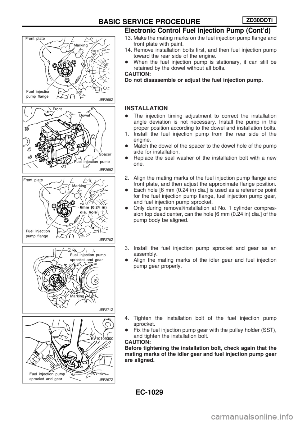
13. Make the mating marks on the fuel injection pump flange and
front plate with paint.
14. Remove installation bolts first, and then fuel injection pump
toward the rear side of the engine.
+When the fuel injection pump is stationary, it can still be
retained by the dowel without all bolts.
CAUTION:
Do not disassemble or adjust the fuel injection pump.
INSTALLATION
+The injection timing adjustment to correct the installation
angle deviation is not necessary. Install the pump in the
proper position according to the dowel and installation bolts.
1. Install the fuel injection pump from the rear side of the
engine.
+Match the dowel of the spacer to the dowel hole of the pump
side for installation.
+Replace the seal washer of the installation bolt with a new
one.
2. Align the mating marks of the fuel injection pump flange and
front plate, and then adjust the approximate flange position.
+Each hole [6 mm (0.24 in) dia.] is used as a reference point
for the fuel injection pump flange, fuel injection pump gear,
and fuel injection pump sprocket.
+Only during removal/installation at No. 1 cylinder compres-
sion top dead center, can the hole [6 mm (0.24 in) dia.] of the
pump body be aligned.
3. Install the fuel injection pump sprocket and gear as an
assembly.
+Align the mating marks of the idler gear and fuel injection
pump gear properly.
4. Tighten the installation bolt of the fuel injection pump
sprocket.
+Fix the fuel injection pump gear with the pulley holder (SST),
and tighten the installation bolt.
CAUTION:
Before tightening the installation bolt, check again that the
mating marks of the idler gear and fuel injection pump gear
are aligned.
JEF268Z
JEF269Z
JEF270Z
JEF271Z
JEF267Z
BASIC SERVICE PROCEDUREZD30DDTi
Electronic Control Fuel Injection Pump (Cont'd)
EC-1029
Page 263 of 1033
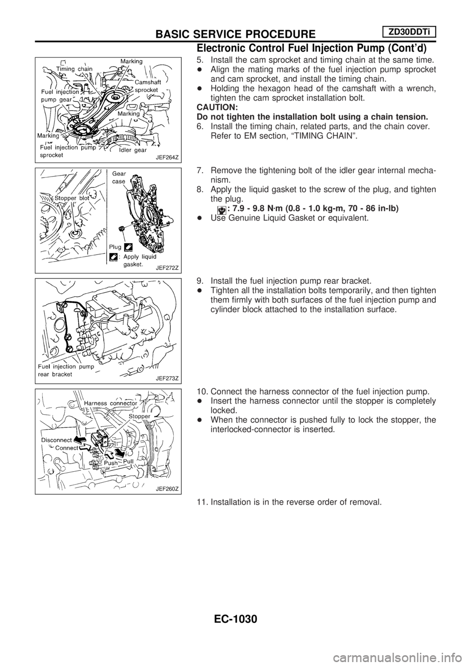
5. Install the cam sprocket and timing chain at the same time.
+Align the mating marks of the fuel injection pump sprocket
and cam sprocket, and install the timing chain.
+Holding the hexagon head of the camshaft with a wrench,
tighten the cam sprocket installation bolt.
CAUTION:
Do not tighten the installation bolt using a chain tension.
6. Install the timing chain, related parts, and the chain cover.
Refer to EM section, ªTIMING CHAINº.
7. Remove the tightening bolt of the idler gear internal mecha-
nism.
8. Apply the liquid gasket to the screw of the plug, and tighten
the plug.
: 7.9 - 9.8 Nzm (0.8 - 1.0 kg-m, 70 - 86 in-lb)
+Use Genuine Liquid Gasket or equivalent.
9. Install the fuel injection pump rear bracket.
+Tighten all the installation bolts temporarily, and then tighten
them firmly with both surfaces of the fuel injection pump and
cylinder block attached to the installation surface.
10. Connect the harness connector of the fuel injection pump.
+Insert the harness connector until the stopper is completely
locked.
+When the connector is pushed fully to lock the stopper, the
interlocked-connector is inserted.
11. Installation is in the reverse order of removal.
JEF264Z
JEF272Z
JEF273Z
JEF260Z
BASIC SERVICE PROCEDUREZD30DDTi
Electronic Control Fuel Injection Pump (Cont'd)
EC-1030
Page 264 of 1033
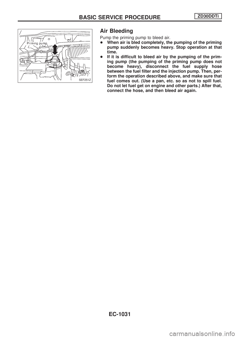
Air Bleeding
Pump the priming pump to bleed air.
+When air is bled completely, the pumping of the priming
pump suddenly becomes heavy. Stop operation at that
time.
+If it is difficult to bleed air by the pumping of the prim-
ing pump (the pumping of the priming pump does not
become heavy), disconnect the fuel supply hose
between the fuel filter and the injection pump. Then, per-
form the operation described above, and make sure that
fuel comes out. (Use a pan, etc. so as not to spill fuel.
Do not let fuel get on engine and other parts.) After that,
connect the hose, and then bleed air again.
SEF251Z
BASIC SERVICE PROCEDUREZD30DDTi
EC-1031
Page 265 of 1033
DTC and MI Detection Logic
When a malfunction is detected, the malfunction (DTC) is stored in the ECM memory.
The MI will light up each time the ECM detects malfunction. For diagnostic items causing the MI to light up,
refer to ªTROUBLE DIAGNOSIS Ð INDEXº, EC-1006.
Diagnostic Trouble Code (DTC)
HOW TO READ DTC
The DTC can be read by the following methods.
Without CONSULT-II
ECM displays the DTC by a set of four digit numbers with MI illumination in the diagnostic test mode II
(Self-diagnostic results). Example: 0102, 0407, 1004, etc.
With CONSULT-II
CONSULT-II displays the DTC in ªSELF-DIAG RESULTSº mode. Examples: ªCRANK POS SEN (TDC)º, etc.
+Output of the trouble code means that the indicated circuit has a malfunction. However, in the
Mode II it does not indicate whether the malfunction is still occurring or occurred in the past and
returned to normal.
CONSULT-II can identify them. Therefore, using CONSULT-II (if available) is recommended.
HOW TO ERASE DTC
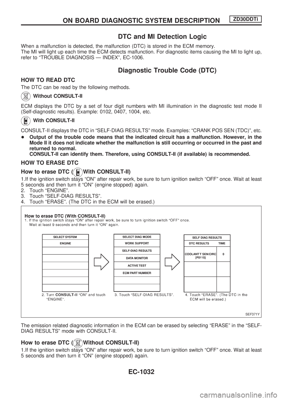
How to erase DTC (
With CONSULT-II)
1.If the ignition switch stays ªONº after repair work, be sure to turn ignition switch ªOFFº once. Wait at least
5 seconds and then turn it ªONº (engine stopped) again.
2. Touch ªENGINEº.
3. Touch ªSELF-DIAG RESULTSº.
4. Touch ªERASEº. (The DTC in the ECM will be erased.)
The emission related diagnostic information in the ECM can be erased by selecting ªERASEº in the ªSELF-
DIAG RESULTSº mode with CONSULT-II.
How to erase DTC (Without CONSULT-II)
1.If the ignition switch stays ªONº after repair work, be sure to turn ignition switch ªOFFº once. Wait at least
5 seconds and then turn it ªONº (engine stopped) again.
SEF371Y
ON BOARD DIAGNOSTIC SYSTEM DESCRIPTIONZD30DDTi
EC-1032
Page 266 of 1033
2. Change the diagnostic test mode from Mode II to Mode I by using the data link connector. (See
EC-1035.)
The emission related diagnostic information in the ECM can be erased by changing the diagnostic test mode.
+If the battery is disconnected, the emission-related diagnostic information will be lost after
approx. 24 hours.
+Erasing the emission-related diagnostic information using CONSULT-II is easier and quicker than
switching the diagnostic test mode using the data link connector.
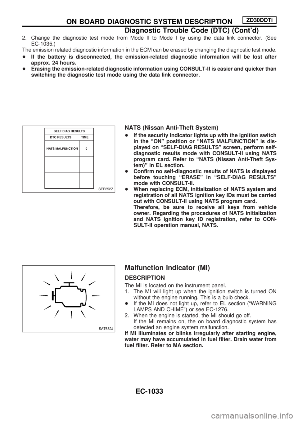
NATS (Nissan Anti-Theft System)
+If the security indicator lights up with the ignition switch
in the ªONº position or ªNATS MALFUNCTIONº is dis-
played on ªSELF-DIAG RESULTSº screen, perform self-
diagnostic results mode with CONSULT-II using NATS
program card. Refer to ªNATS (Nissan Anti-Theft Sys-
tem)º in EL section.
+Confirm no self-diagnostic results of NATS is displayed
before touching ªERASEº in ªSELF-DIAG RESULTSº
mode with CONSULT-II.
+When replacing ECM, initialization of NATS system and
registration of all NATS ignition key IDs must be carried
out with CONSULT-II using NATS program card.
Therefore, be sure to receive all keys from vehicle
owner. Regarding the procedures of NATS initialization
and NATS ignition key ID registration, refer to CON-
SULT-II operation manual, NATS.
Malfunction Indicator (MI)
DESCRIPTION
The MI is located on the instrument panel.
1. The MI will light up when the ignition switch is turned ON
without the engine running. This is a bulb check.
+If the MI does not light up, refer to EL section (ªWARNING
LAMPS AND CHIMEº) or see EC-1276.
2. When the engine is started, the MI should go off.
If the MI remains on, the on board diagnostic system has
detected an engine system malfunction.
If MI illuminates or blinks irregularly after starting engine,
water may have accumulated in fuel filter. Drain water from
fuel filter. Refer to MA section.
SEF252Z
SAT652J
ON BOARD DIAGNOSTIC SYSTEM DESCRIPTIONZD30DDTi
Diagnostic Trouble Code (DTC) (Cont'd)
EC-1033
Page 267 of 1033
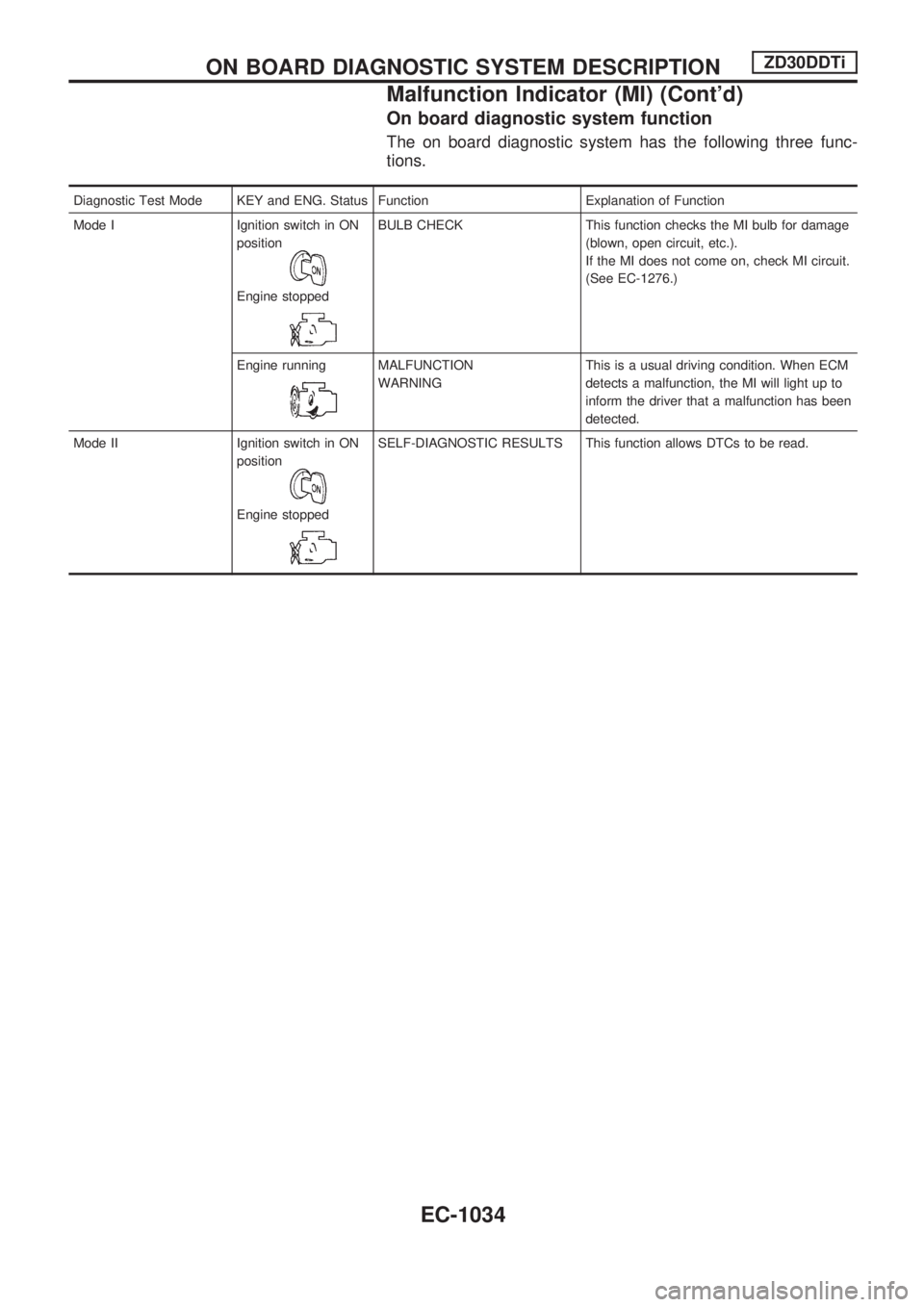
On board diagnostic system function
The on board diagnostic system has the following three func-
tions.
Diagnostic Test Mode KEY and ENG. Status Function Explanation of Function
Mode I Ignition switch in ON
position
Engine stopped
BULB CHECK This function checks the MI bulb for damage
(blown, open circuit, etc.).
If the MI does not come on, check MI circuit.
(See EC-1276.)
Engine running
MALFUNCTION
WARNINGThis is a usual driving condition. When ECM
detects a malfunction, the MI will light up to
inform the driver that a malfunction has been
detected.
Mode II Ignition switch in ON
position
Engine stopped
SELF-DIAGNOSTIC RESULTS This function allows DTCs to be read.
ON BOARD DIAGNOSTIC SYSTEM DESCRIPTIONZD30DDTi
Malfunction Indicator (MI) (Cont'd)
EC-1034
Page 268 of 1033
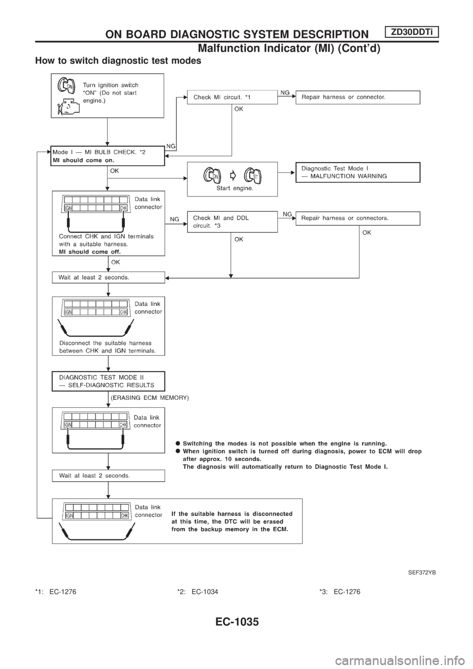
How to switch diagnostic test modes
*1: EC-1276 *2: EC-1034 *3: EC-1276
SEF372YB
ON BOARD DIAGNOSTIC SYSTEM DESCRIPTIONZD30DDTi
Malfunction Indicator (MI) (Cont'd)
EC-1035
Page 269 of 1033
Diagnostic test mode I Ð Bulb check
In this mode, the MI on the instrument panel should stay ON. If it remains OFF, check the bulb. Refer to EL
section, ªWARNING LAMPS AND CHIMEº or see EC-1276.
Diagnostic test mode I Ð Malfunction warning
MI Condition
ON When the malfunction is detected or the ECM's CPU is malfunctioning.
OFF No malfunction.
Diagnostic test mode II Ð Self-diagnostic results
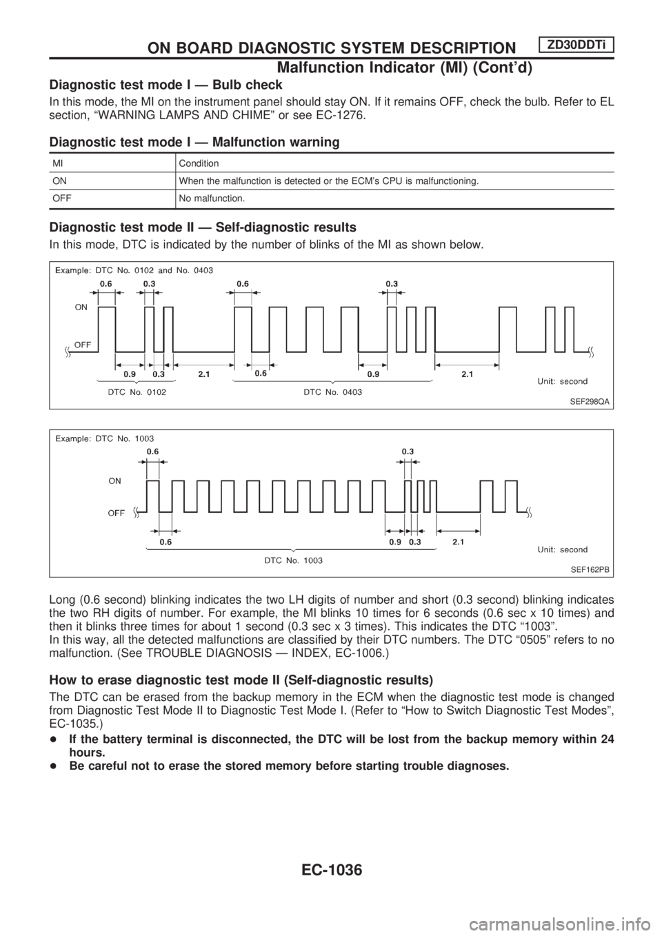
In this mode, DTC is indicated by the number of blinks of the MI as shown below.
Long (0.6 second) blinking indicates the two LH digits of number and short (0.3 second) blinking indicates
the two RH digits of number. For example, the MI blinks 10 times for 6 seconds (0.6 sec x 10 times) and
then it blinks three times for about 1 second (0.3 sec x 3 times). This indicates the DTC ª1003º.
In this way, all the detected malfunctions are classified by their DTC numbers. The DTC ª0505º refers to no
malfunction. (See TROUBLE DIAGNOSIS Ð INDEX, EC-1006.)
How to erase diagnostic test mode II (Self-diagnostic results)
The DTC can be erased from the backup memory in the ECM when the diagnostic test mode is changed
from Diagnostic Test Mode II to Diagnostic Test Mode I. (Refer to ªHow to Switch Diagnostic Test Modesº,
EC-1035.)
+If the battery terminal is disconnected, the DTC will be lost from the backup memory within 24
hours.
+Be careful not to erase the stored memory before starting trouble diagnoses.
SEF298QA
SEF162PB
ON BOARD DIAGNOSTIC SYSTEM DESCRIPTIONZD30DDTi
Malfunction Indicator (MI) (Cont'd)
EC-1036
Page 270 of 1033
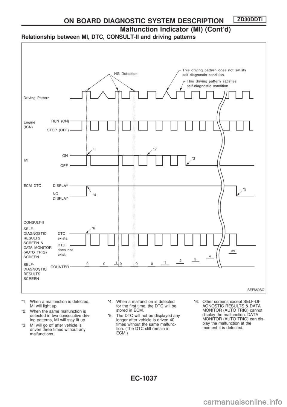
Relationship between MI, DTC, CONSULT-II and driving patterns
*1: When a malfunction is detected,
MI will light up.
*2: When the same malfunction is
detected in two consecutive driv-
ing patterns, MI will stay lit up.
*3: MI will go off after vehicle is
driven three times without any
malfunctions.*4: When a malfunction is detected
for the first time, the DTC will be
stored in ECM.
*5: The DTC will not be displayed any
longer after vehicle is driven 40
times without the same malfunc-
tion. (The DTC still remain in
ECM.)*6: Other screens except SELF-DI-
AGNOSTIC RESULTS & DATA
MONITOR (AUTO TRIG) cannot
display the malfunction. DATA
MONITOR (AUTO TRIG) can dis-
play the malfunction at the
moment it is detected.
SEF659SC
ON BOARD DIAGNOSTIC SYSTEM DESCRIPTIONZD30DDTi
Malfunction Indicator (MI) (Cont'd)
EC-1037