NISSAN PATROL 2000 Electronic Repair Manual
PATROL 2000
NISSAN
NISSAN
https://www.carmanualsonline.info/img/5/57367/w960_57367-0.png
NISSAN PATROL 2000 Electronic Repair Manual
Trending: rear break, check engine, Diff, automatic transmission, transmission oil, turn signal, alternator
Page 221 of 1033
VA
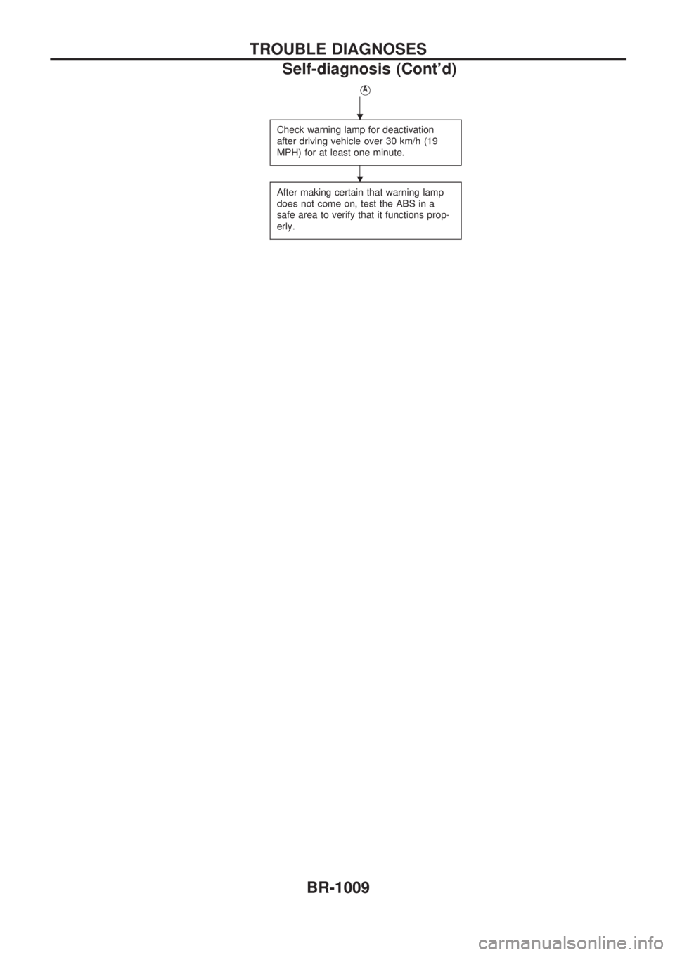
Check warning lamp for deactivation
after driving vehicle over 30 km/h (19
MPH) for at least one minute.
After making certain that warning lamp
does not come on, test the ABS in a
safe area to verify that it functions prop-
erly.
.
.
TROUBLE DIAGNOSES
Self-diagnosis (Cont'd)
BR-1009
Page 222 of 1033
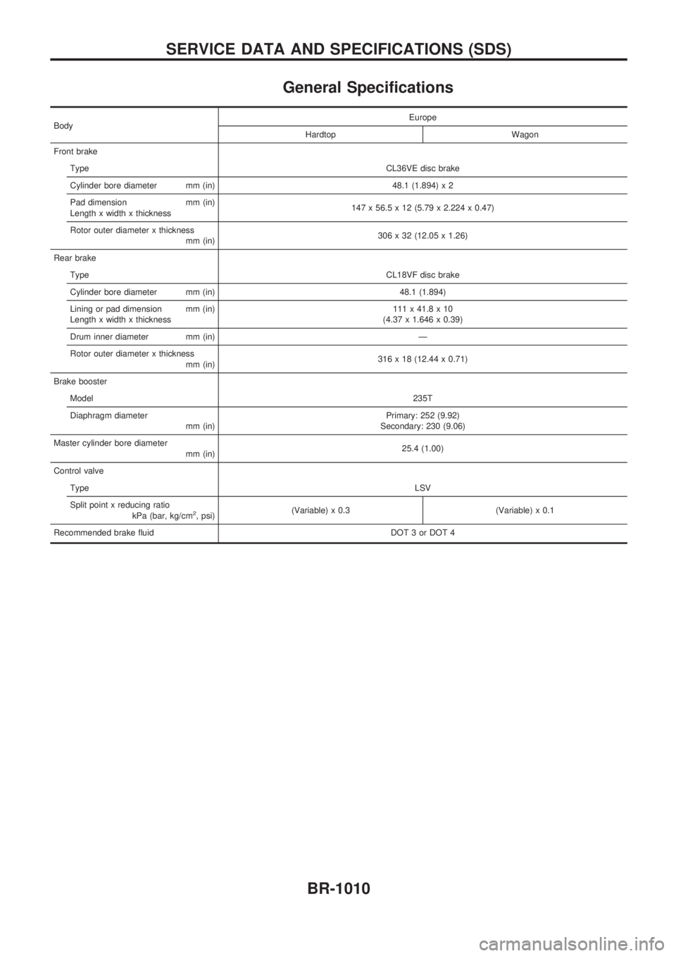
General Specifications
BodyEurope
Hardtop Wagon
Front brake
TypeCL36VE disc brake
Cylinder bore diameter mm (in) 48.1 (1.894) x 2
Pad dimension mm (in)
Length x width x thickness147 x 56.5 x 12 (5.79 x 2.224 x 0.47)
Rotor outer diameter x thickness
mm (in)306 x 32 (12.05 x 1.26)
Rear brake
TypeCL18VF disc brake
Cylinder bore diameter mm (in) 48.1 (1.894)
Lining or pad dimension mm (in)
Length x width x thickness111 x 41.8 x 10
(4.37 x 1.646 x 0.39)
Drum inner diameter mm (in) Ð
Rotor outer diameter x thickness
mm (in)316 x 18 (12.44 x 0.71)
Brake booster
Model235T
Diaphragm diameter
mm (in)Primary: 252 (9.92)
Secondary: 230 (9.06)
Master cylinder bore diameter
mm (in)25.4 (1.00)
Control valve
TypeLSV
Split point x reducing ratio
kPa (bar, kg/cm
2, psi)(Variable) x 0.3 (Variable) x 0.1
Recommended brake fluid DOT 3 or DOT 4
SERVICE DATA AND SPECIFICATIONS (SDS)
BR-1010
Page 223 of 1033
BODY & TRIM
SECTION
BT
MODIFICATION NOTICE:
+ The door trim has been changed.
+ The front seat with side air bag has been added.
+ An auto reverse function has been added to the driver's door window.
CONTENTS
PRECAUTIONS ................................................... 1002
Supplemental Restraint System (SRS) ªAIR
BAGº and ªSEAT BELT PRE-TENSIONERº ... 1002
DOOR ................................................................... 1003
Front Door Limit Switch Reset (Driver side
only) ................................................................. 1003 INTERIOR TRIM
.................................................. 1004
Door Trim ......................................................... 1004
SEAT .................................................................... 1006
Front Seat ........................................................ 1006
MIRROR ............................................................... 1007
Door Mirror ....................................................... 1007
BT
Page 224 of 1033
Supplemental Restraint System (SRS) ªAIR
BAGº and ªSEAT BELT PRE-TENSIONERº
The Supplemental Restraint System such as ªAIR BAGº and ªSEAT BELT PRE-TENSIONERº used along
with a seat belt, helps to reduce the risk or severity of injury to the driver and front passenger for certain
types of collision. The SRS system composition which is available to NISSAN MODEL Y61 is as follows (The
composition varies according to the destination and optional equipment.):
+For a frontal collision
The Supplemental Restraint System consists of driver air bag module (located in the center of the
steering wheel), front passenger air bag module (located on the instrument panel on passenger side),
seat belt pre-tensioners, a diagnosis sensor unit, warning lamp, wiring harness and spiral cable.
+ For a side collision
The Supplemental Restraint System consists of front side air bag module (located in the outer side of
front seat), satellite sensor, diagnosis sensor unit (one of components of air bags for a frontal collision),
wiring harness, warning lamp (one of components of air bags for a frontal collision).
Information necessary to service the system safely is included in the RS sectionof this Service Manual.
WARNING:
+ To avoid rendering the SRS inoperative, which could increase the risk of personal injury or death
in the event of a collision which would result in air bag inflation, all maintenance should be per-
formed by an authorized NISSAN dealer.
+ Improper maintenance, including incorrect removal and installation of the SRS, can lead to per-
sonal injury caused by intentional activation of the system. For removal of Spiral Cable and Air
Bag Module, see the RS section.
+ Do not use electrical test equipment on any circuit related to the SRS unless instructed to in this
Service Manual. Spiral cable and wiring harnesses covered with yellow insulation tape either just
before the harness connectors or for the complete harness are related to the SRS.
PRECAUTIONS
BT-1002
Page 225 of 1033
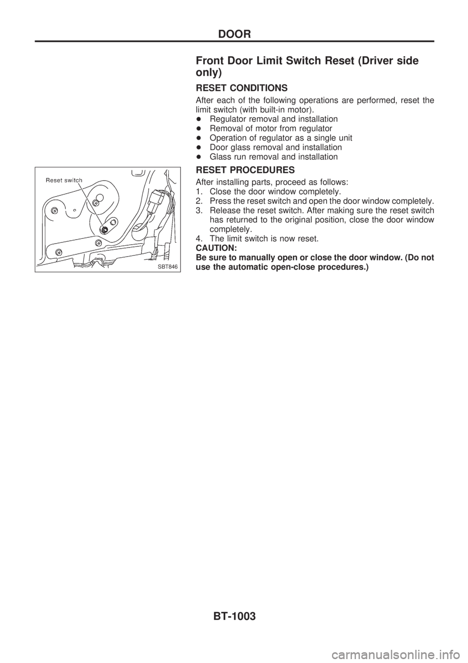
Front Door Limit Switch Reset (Driver side
only)
RESET CONDITIONS
After each of the following operations are performed, reset the
limit switch (with built-in motor).
+Regulator removal and installation
+ Removal of motor from regulator
+ Operation of regulator as a single unit
+ Door glass removal and installation
+ Glass run removal and installation
RESET PROCEDURES
After installing parts, proceed as follows:
1. Close the door window completely.
2. Press the reset switch and open the door window completely.
3. Release the reset switch. After making sure the reset switch
has returned to the original position, close the door window
completely.
4. The limit switch is now reset.
CAUTION:
Be sure to manually open or close the door window. (Do not
use the automatic open-close procedures.)
SBT846
DOOR
BT-1003
Page 226 of 1033
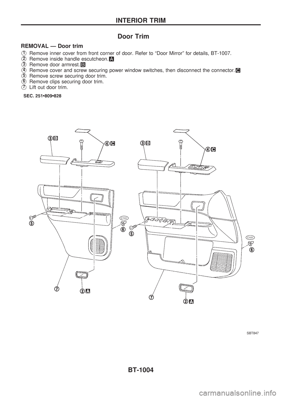
Door Trim
REMOVAL Ð Door trim
V1Remove inner cover from front corner of door. Refer to ªDoor Mirrorº for details, BT-1007.
V2Remove inside handle escutcheon.
V3Remove door armrest.
V4Remove cover and screw securing power window switches, then disconnect the connector.
V5Remove screw securing door trim.
V6Remove clips securing door trim.
V7Lift out door trim.
SBT847
INTERIOR TRIM
BT-1004
Page 227 of 1033
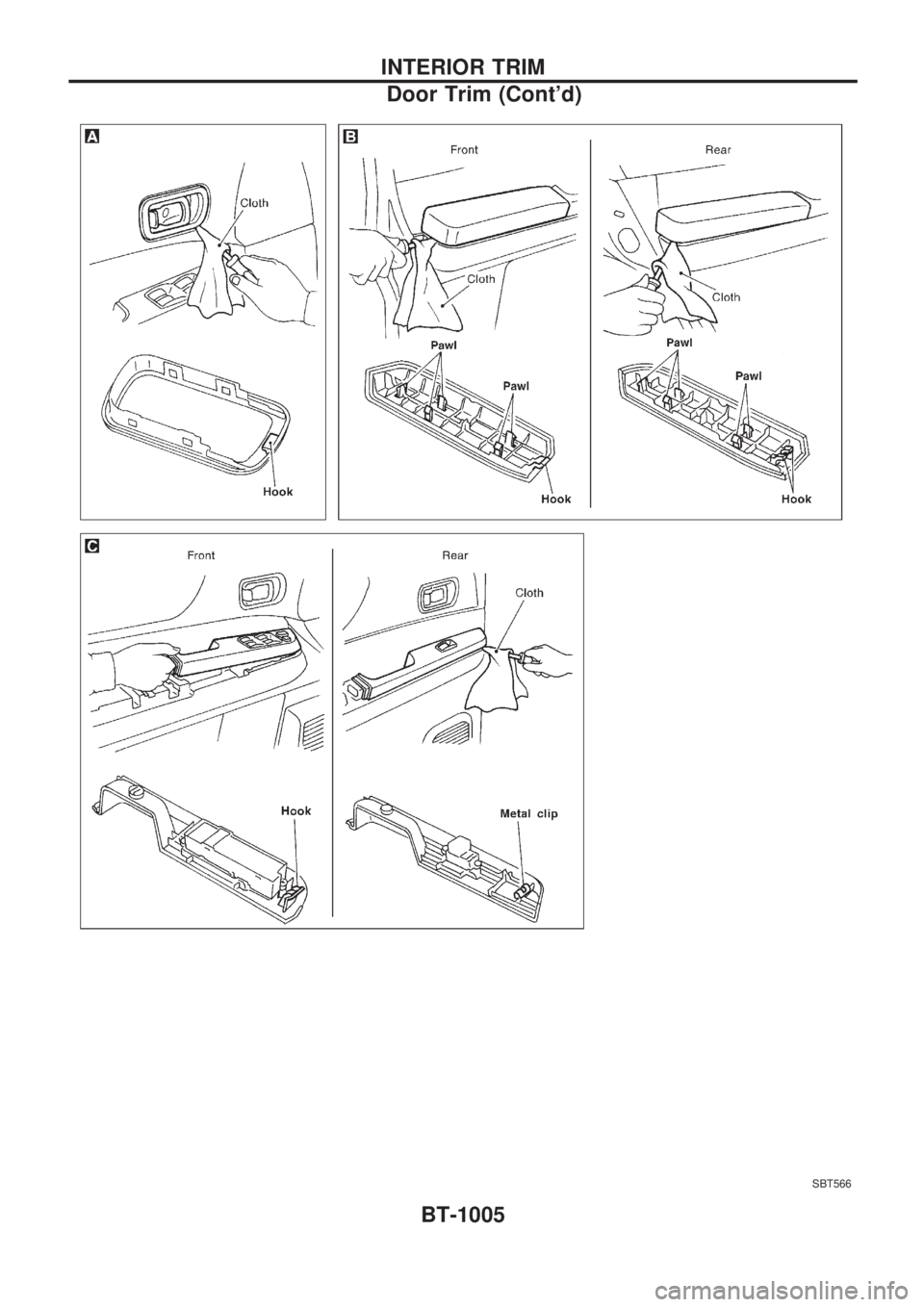
SBT566
INTERIOR TRIM
Door Trim (Cont'd)BT-1005
Page 228 of 1033
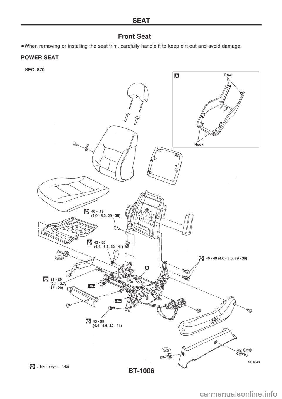
Front Seat
+When removing or installing the seat trim, carefully handle it to keep dirt out and avoid damage.
POWER SEAT
SBT848
SEAT
BT-1006
Page 229 of 1033
Door Mirror
CAUTION:
Be careful not to scratch door rearview mirror body.
HFor Wiring Diagram, refer to ªPOWER DOOR MIRRORº in EL section.
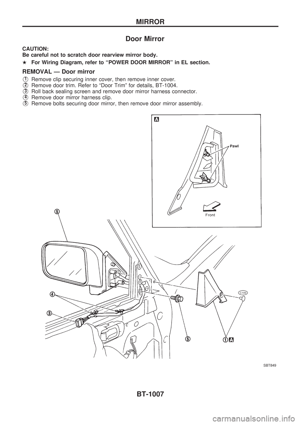
REMOVAL Ð Door mirror
V1Remove clip securing inner cover, then remove inner cover.
V2Remove door trim. Refer to ªDoor Trimº for details, BT-1004.
V3Roll back sealing screen and remove door mirror harness connector.
V4Remove door mirror harness clip.
V5Remove bolts securing door mirror, then remove door mirror assembly.
SBT849
MIRROR
BT-1007
Page 230 of 1033
CLUTCH
SECTION
CL
MODIFICATION NOTICE:
+The ZD30DDTi engine model has been added.
CONTENTS
CLUTCH SYSTEM............................................... 1002
HYDRAULIC CLUTCH CONTROL..................... 1003
Clutch Operating Cylinder................................ 1003
SERVICE DATA AND SPECIFICATIONS
(SDS).................................................................... 1004General Specifications ..................................... 1004
Inspection and Adjustment .............................. 1004
CL
Trending: Differential carrier, cooling, timing belt, airbag off, brake rotor, window, turn signal
