NISSAN PATROL 2006 Service Manual
PATROL 2006
NISSAN
NISSAN
https://www.carmanualsonline.info/img/5/57368/w960_57368-0.png
NISSAN PATROL 2006 Service Manual
Trending: fuse box location, transmission, tire type, oil reset, towing, brake pads replacement, low beam
Page 831 of 1226
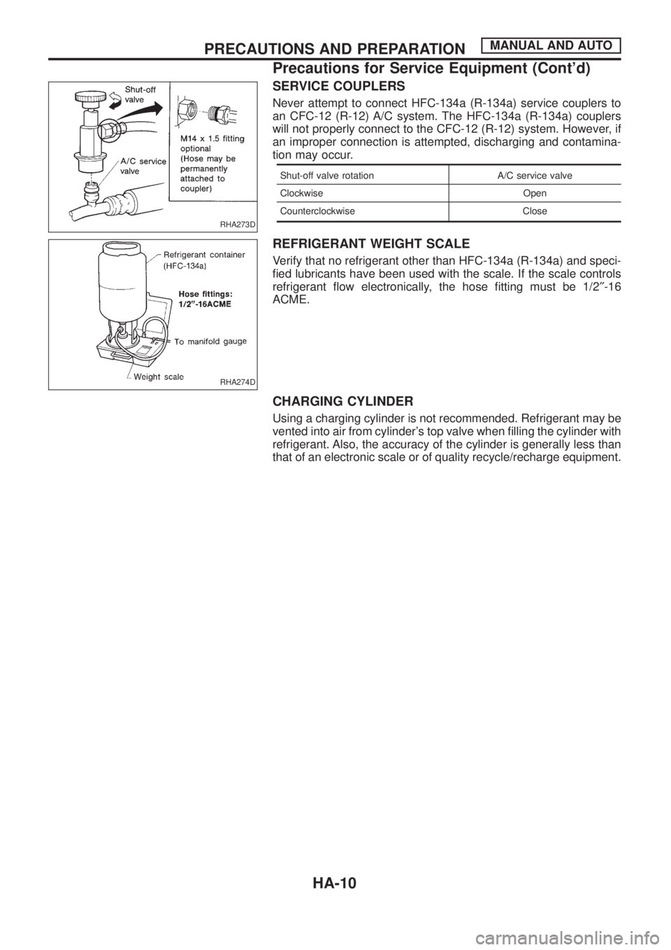
SERVICE COUPLERS
Never attempt to connect HFC-134a (R-134a) service couplers to
an CFC-12 (R-12) A/C system. The HFC-134a (R-134a) couplers
will not properly connect to the CFC-12 (R-12) system. However, if
an improper connection is attempted, discharging and contamina-
tion may occur.
Shut-off valve rotation A/C service valve
Clockwise Open
Counterclockwise Close
REFRIGERANT WEIGHT SCALE
Verify that no refrigerant other than HFC-134a (R-134a) and speci-
®ed lubricants have been used with the scale. If the scale controls
refrigerant ¯ow electronically, the hose ®tting must be 1/2²-16
ACME.
CHARGING CYLINDER
Using a charging cylinder is not recommended. Refrigerant may be
vented into air from cylinder's top valve when ®lling the cylinder with
refrigerant. Also, the accuracy of the cylinder is generally less than
that of an electronic scale or of quality recycle/recharge equipment.
RHA273D
RHA274D
PRECAUTIONS AND PREPARATIONMANUAL AND AUTO
Precautions for Service Equipment (Cont'd)
HA-10
Page 832 of 1226
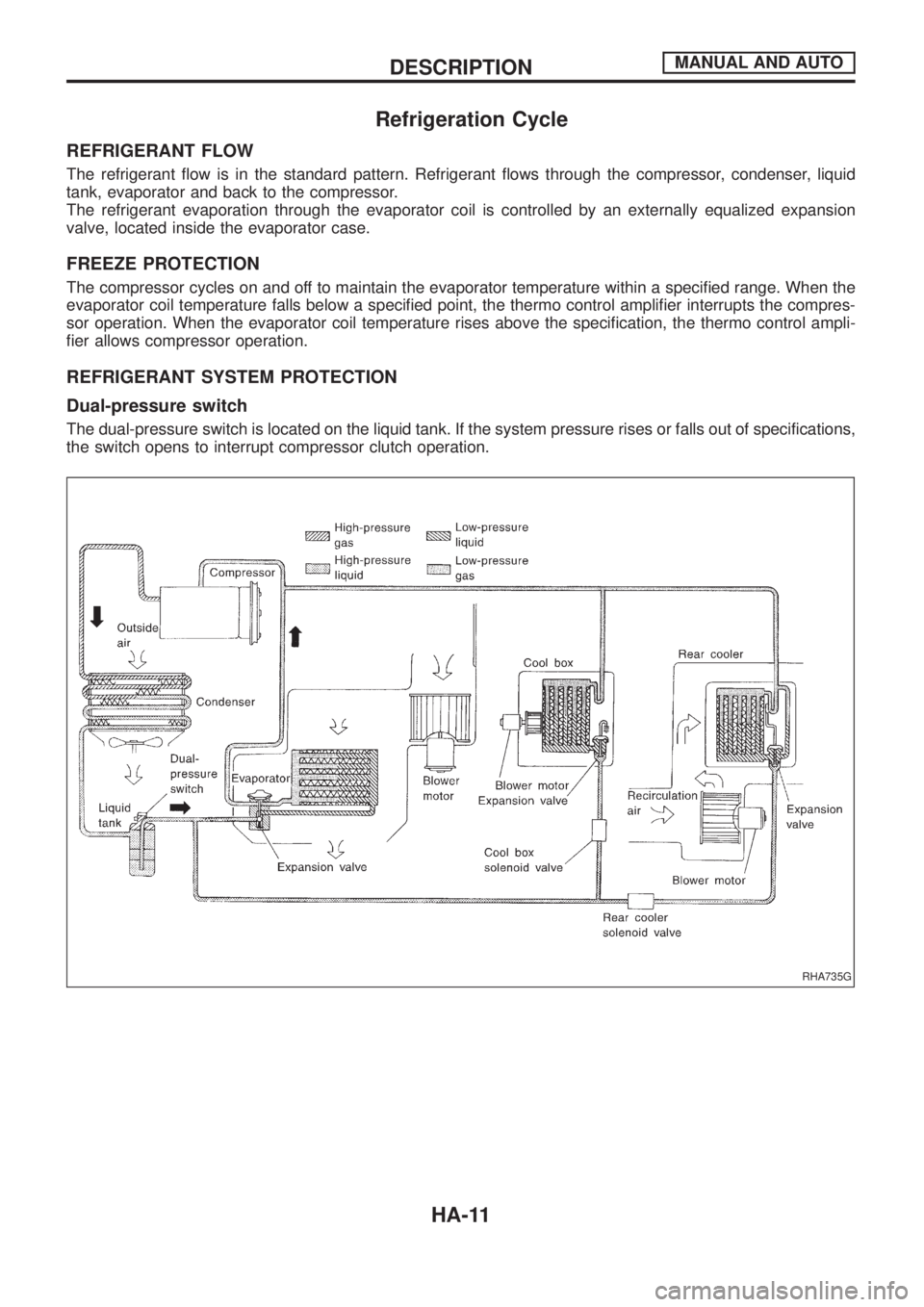
Refrigeration Cycle
REFRIGERANT FLOW
The refrigerant ¯ow is in the standard pattern. Refrigerant ¯ows through the compressor, condenser, liquid
tank, evaporator and back to the compressor.
The refrigerant evaporation through the evaporator coil is controlled by an externally equalized expansion
valve, located inside the evaporator case.
FREEZE PROTECTION
The compressor cycles on and off to maintain the evaporator temperature within a speci®ed range. When the
evaporator coil temperature falls below a speci®ed point, the thermo control ampli®er interrupts the compres-
sor operation. When the evaporator coil temperature rises above the speci®cation, the thermo control ampli-
®er allows compressor operation.
REFRIGERANT SYSTEM PROTECTION
Dual-pressure switch
The dual-pressure switch is located on the liquid tank. If the system pressure rises or falls out of specifications,
the switch opens to interrupt compressor clutch operation.
RHA735G
DESCRIPTIONMANUAL AND AUTO
HA-11
Page 833 of 1226
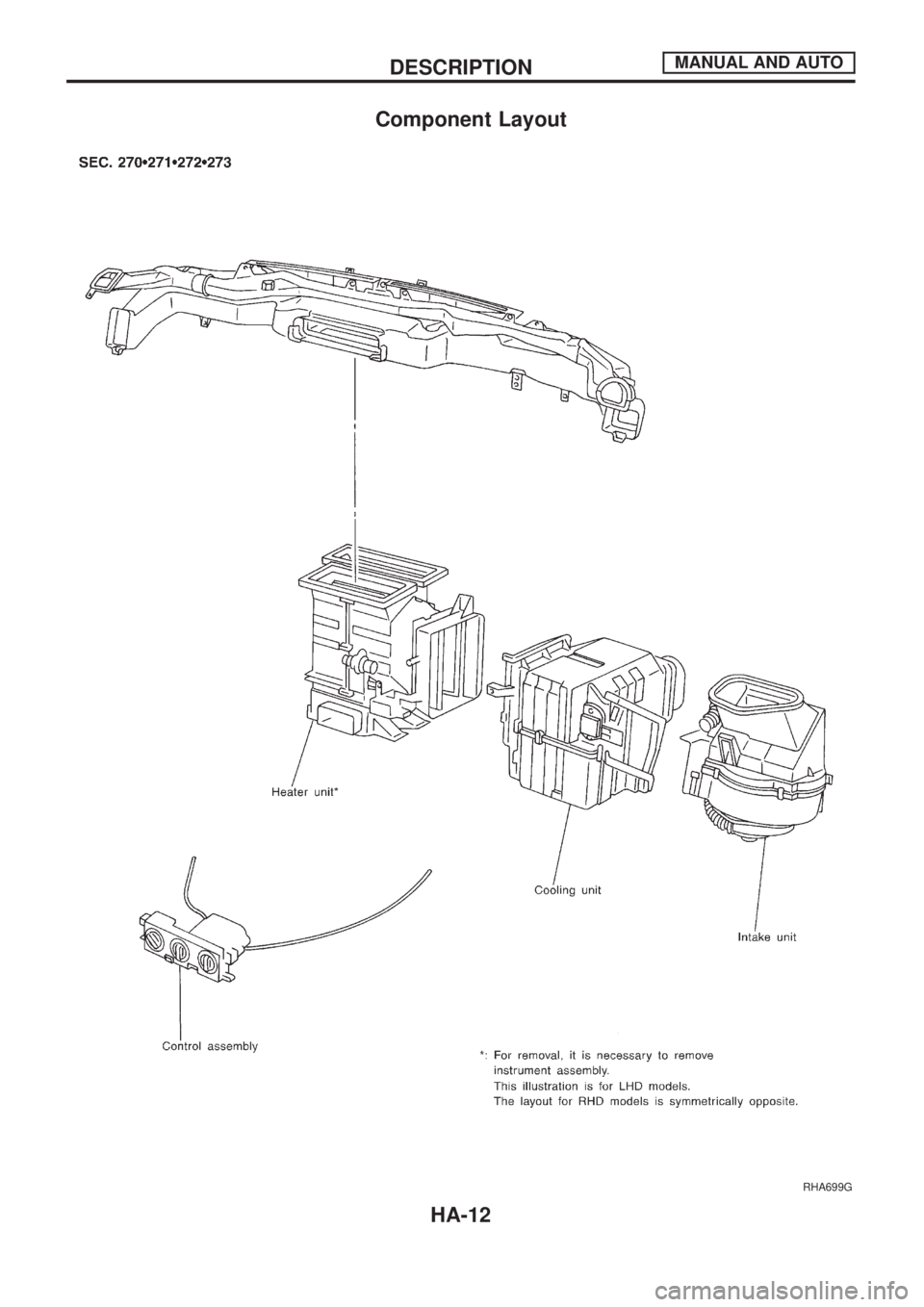
Component Layout
RHA699G
DESCRIPTIONMANUAL AND AUTO
HA-12
Page 834 of 1226
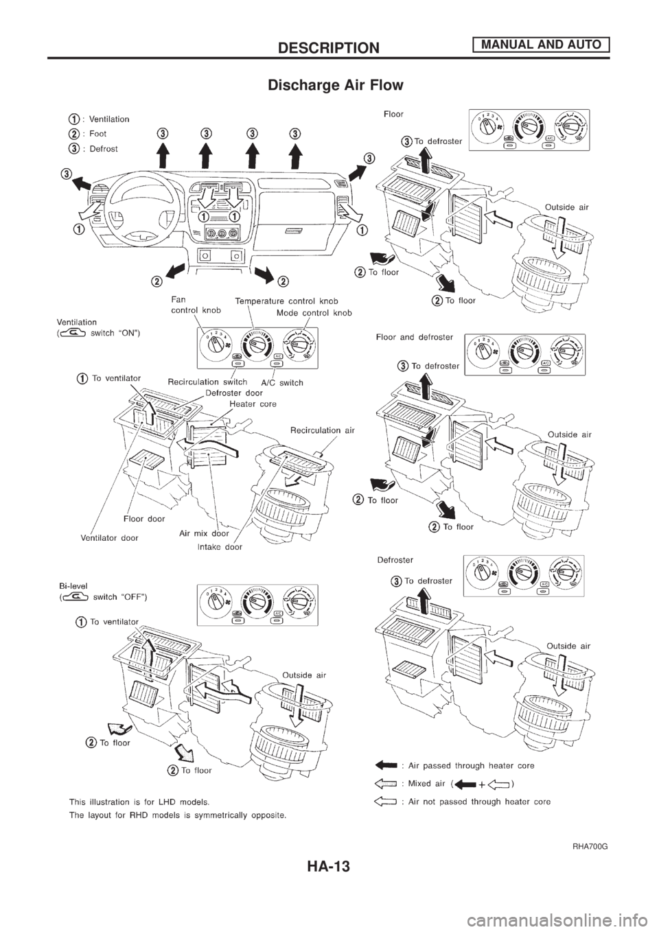
Discharge Air Flow
RHA700G
DESCRIPTIONMANUAL AND AUTO
HA-13
Page 835 of 1226
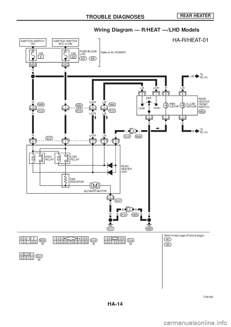
Wiring Diagram Ð R/HEAT Ð/LHD Models
THA165
TROUBLE DIAGNOSESREAR HEATER
HA-14
Page 836 of 1226
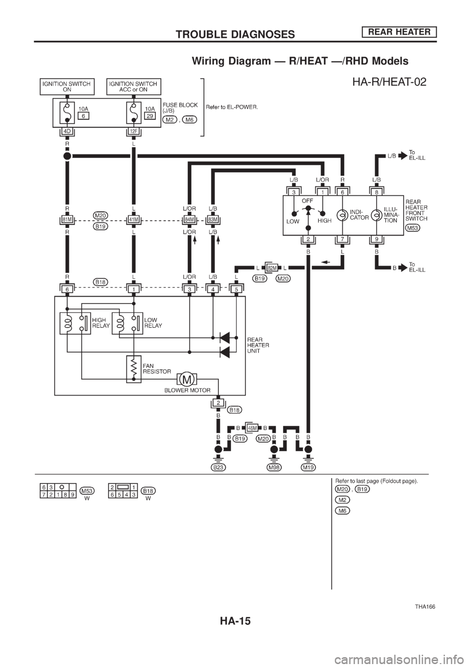
Wiring Diagram Ð R/HEAT Ð/RHD Models
THA166
TROUBLE DIAGNOSESREAR HEATER
HA-15
Page 837 of 1226
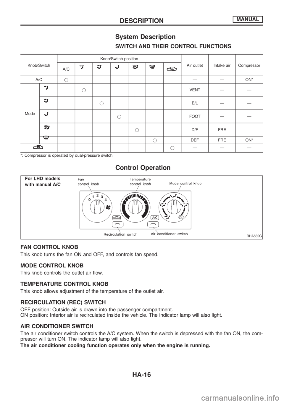
System Description
SWITCH AND THEIR CONTROL FUNCTIONS
Knob/SwitchKnob/Switch position
Air outlet Intake air Compressor
A/C
A/CjÐ Ð ON*
Mode
jVENT Ð Ð
jB/L Ð Ð
jFOOT Ð Ð
jD/F FRE Ð
jDEF FRE ON*
jÐÐÐ
*: Compressor is operated by dual-pressure switch.
Control Operation
FAN CONTROL KNOB
This knob turns the fan ON and OFF, and controls fan speed.
MODE CONTROL KNOB
This knob controls the outlet air ¯ow.
TEMPERATURE CONTROL KNOB
This knob allows adjustment of the temperature of the outlet air.
RECIRCULATION (REC) SWITCH
OFF position: Outside air is drawn into the passenger compartment.
ON position: Interior air is recirculated inside the vehicle. The indicator lamp will also light.
AIR CONDITIONER SWITCH
The air conditioner switch controls the A/C system. When the switch is depressed with the fan ON, the com-
pressor will turn ON. The indicator lamp will also light.
The air conditioner cooling function operates only when the engine is running.
RHA582G
DESCRIPTIONMANUAL
HA-16
Page 838 of 1226
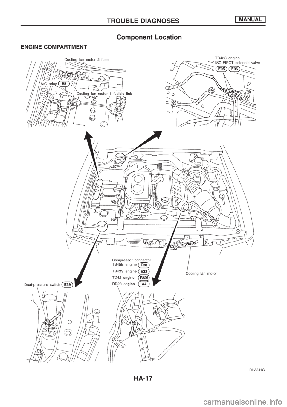
Component Location
ENGINE COMPARTMENT
RHA641G
TROUBLE DIAGNOSESMANUAL
HA-17
Page 839 of 1226
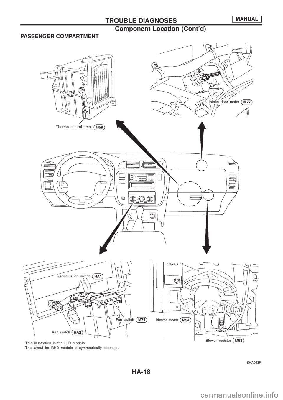
PASSENGER COMPARTMENT
SHA063F
TROUBLE DIAGNOSESMANUAL
Component Location (Cont'd)
HA-18
Page 840 of 1226
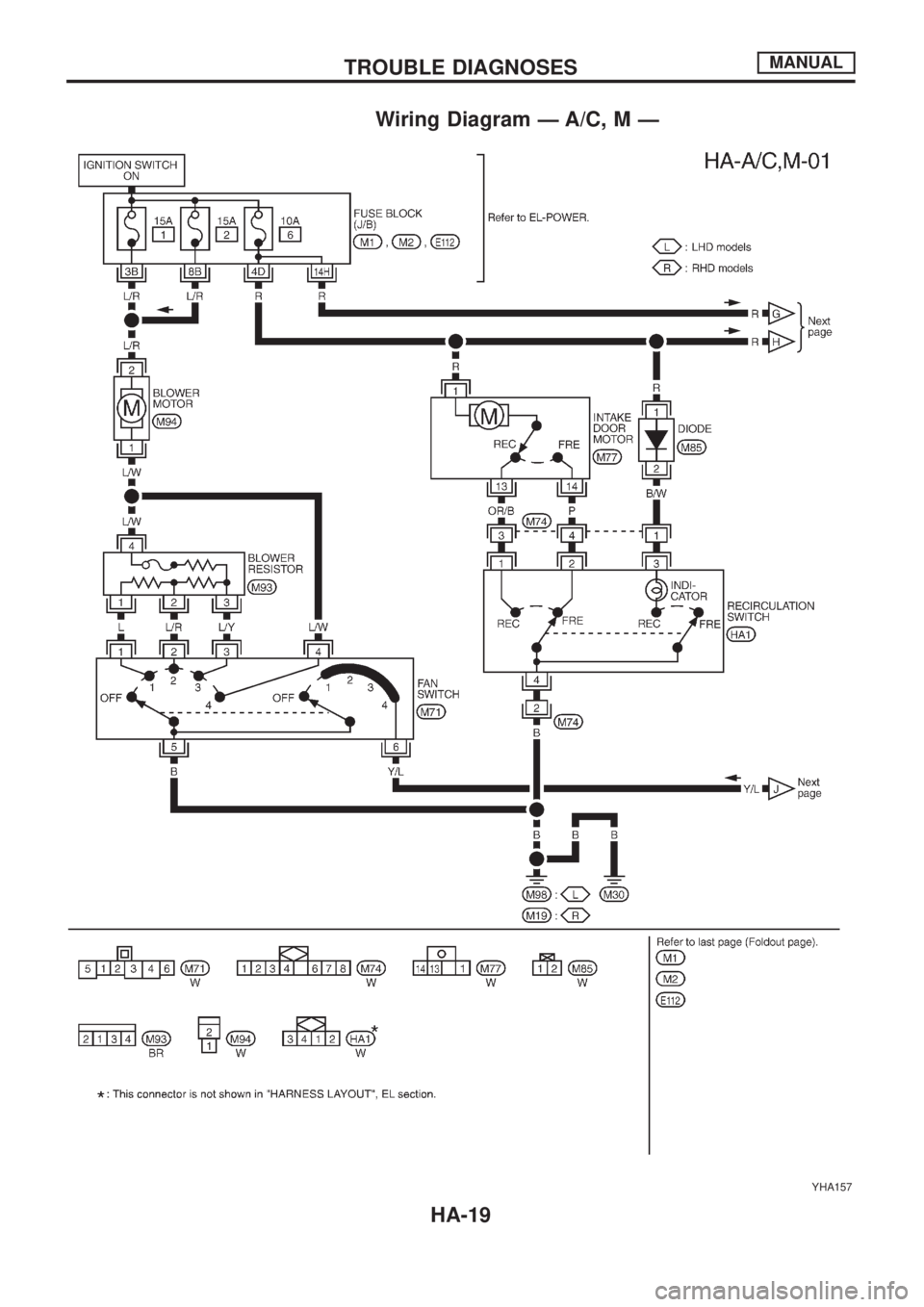
Wiring Diagram Ð A/C, M Ð
YHA157
TROUBLE DIAGNOSESMANUAL
HA-19
Trending: tire size, air filter, maintenance, wheel bolts, gas type, Electrical, oil

