wheel size NISSAN PICK-UP 1998 Repair Manual
[x] Cancel search | Manufacturer: NISSAN, Model Year: 1998, Model line: PICK-UP, Model: NISSAN PICK-UP 1998Pages: 1659, PDF Size: 53.39 MB
Page 68 of 1659
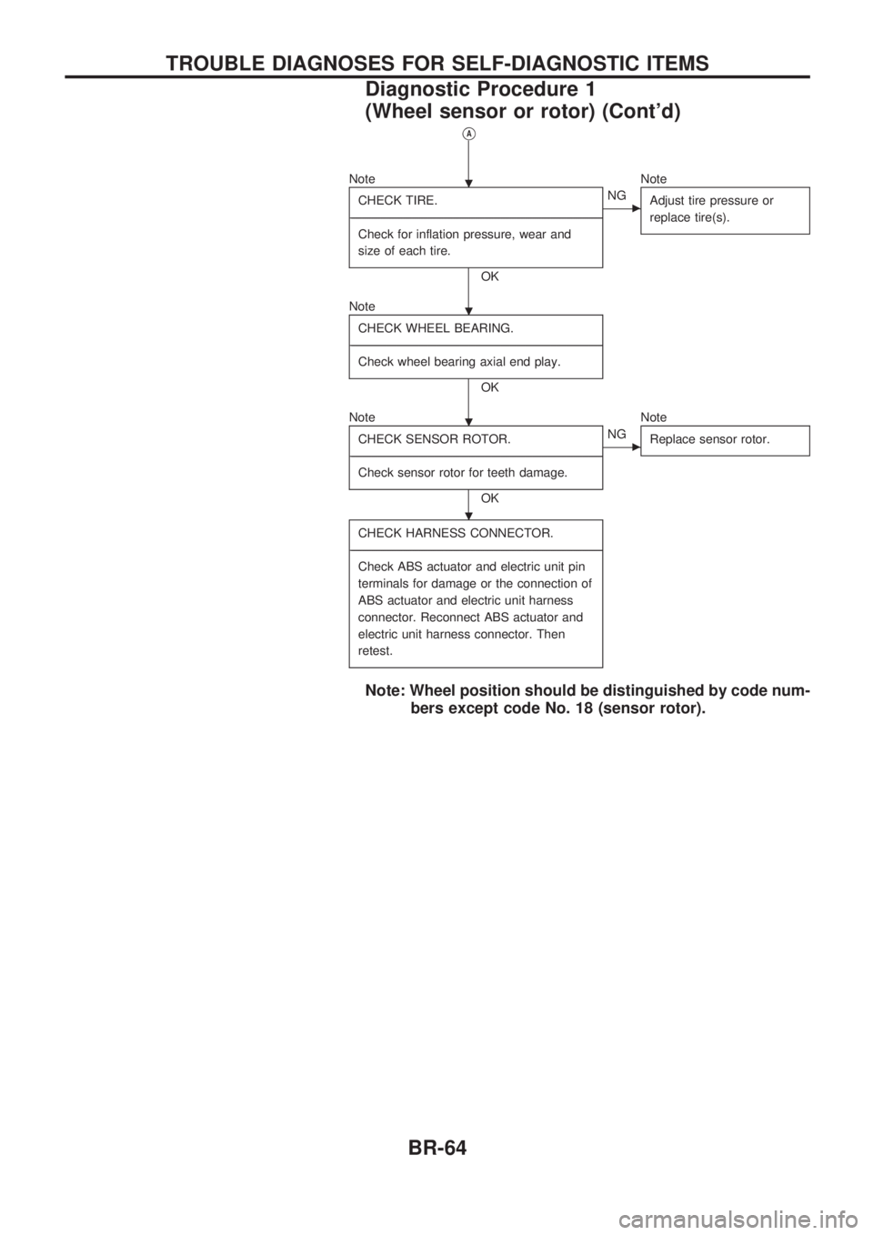
VA
Note
CHECK TIRE.
-------------------------------------------------------------------------------------------------------------------------------------------------------------------------------------------------------------------------------------------------------------------------------------------------------------
Check for inflation pressure, wear and
size of each tire.
OK
cNGNote
Adjust tire pressure or
replace tire(s).
Note
CHECK WHEEL BEARING.
-------------------------------------------------------------------------------------------------------------------------------------------------------------------------------------------------------------------------------------------------------------------------------------------------------------
Check wheel bearing axial end play.
OK
Note
CHECK SENSOR ROTOR.
-------------------------------------------------------------------------------------------------------------------------------------------------------------------------------------------------------------------------------------------------------------------------------------------------------------
Check sensor rotor for teeth damage.
OK
cNGNote
Replace sensor rotor.
CHECK HARNESS CONNECTOR.
-------------------------------------------------------------------------------------------------------------------------------------------------------------------------------------------------------------------------------------------------------------------------------------------------------------
Check ABS actuator and electric unit pin
terminals for damage or the connection of
ABS actuator and electric unit harness
connector. Reconnect ABS actuator and
electric unit harness connector. Then
retest.
Note: Wheel position should be distinguished by code num-
bers except code No. 18 (sensor rotor).
.
.
.
.
TROUBLE DIAGNOSES FOR SELF-DIAGNOSTIC ITEMS
Diagnostic Procedure 1
(Wheel sensor or rotor) (Cont'd)
BR-64
Page 690 of 1659
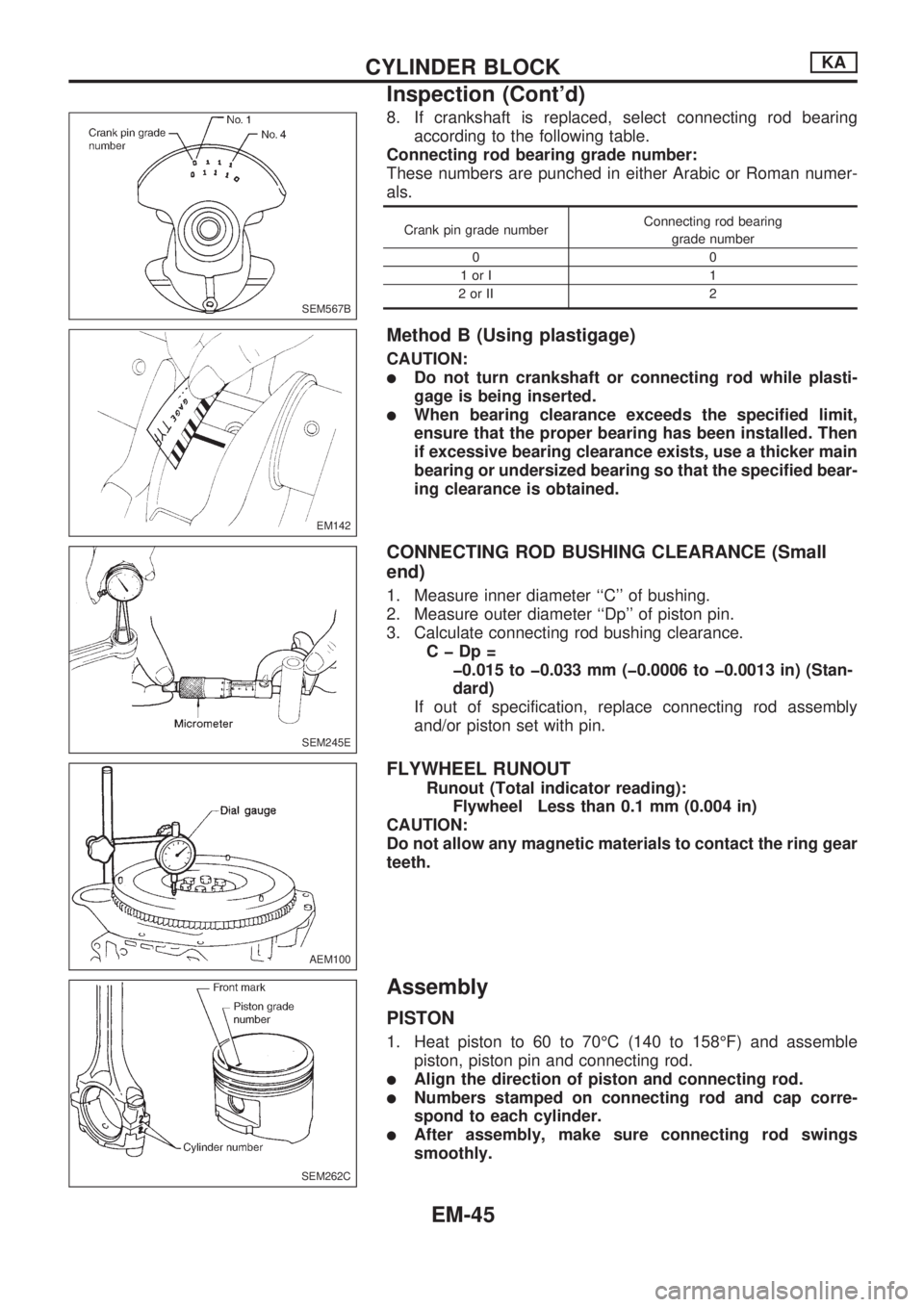
8. If crankshaft is replaced, select connecting rod bearing
according to the following table.
Connecting rod bearing grade number:
These numbers are punched in either Arabic or Roman numer-
als.
Crank pin grade numberConnecting rod bearing
grade number
00
1orI 1
2orII 2
Method B (Using plastigage)
CAUTION:
lDo not turn crankshaft or connecting rod while plasti-
gage is being inserted.
lWhen bearing clearance exceeds the specified limit,
ensure that the proper bearing has been installed. Then
if excessive bearing clearance exists, use a thicker main
bearing or undersized bearing so that the specified bear-
ing clearance is obtained.
CONNECTING ROD BUSHING CLEARANCE (Small
end)
1. Measure inner diameter ``C'' of bushing.
2. Measure outer diameter ``Dp'' of piston pin.
3. Calculate connecting rod bushing clearance.
CþDp=
þ0.015 to þ0.033 mm (þ0.0006 to þ0.0013 in) (Stan-
dard)
If out of specification, replace connecting rod assembly
and/or piston set with pin.
FLYWHEEL RUNOUT
Runout (Total indicator reading):
Flywheel Less than 0.1 mm (0.004 in)
CAUTION:
Do not allow any magnetic materials to contact the ring gear
teeth.
Assembly
PISTON
1. Heat piston to 60 to 70ÉC (140 to 158ÉF) and assemble
piston, piston pin and connecting rod.
lAlign the direction of piston and connecting rod.
lNumbers stamped on connecting rod and cap corre-
spond to each cylinder.
lAfter assembly, make sure connecting rod swings
smoothly.
SEM567B
EM142
SEM245E
AEM100
SEM262C
CYLINDER BLOCKKA
Inspection (Cont'd)
EM-45
Page 742 of 1659
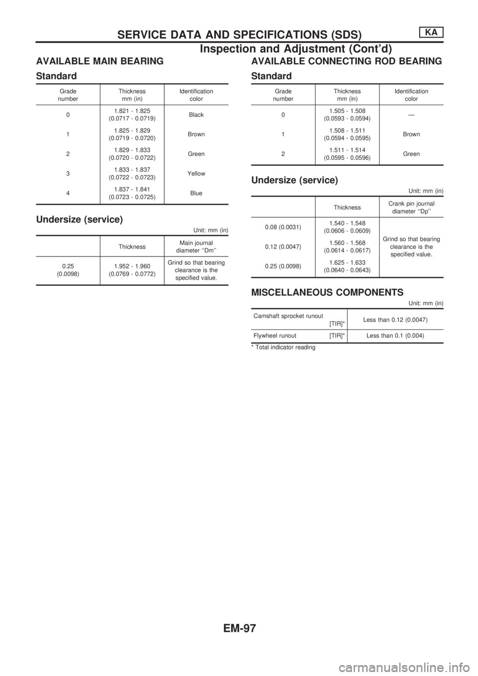
AVAILABLE MAIN BEARING
Standard
Grade
numberThickness
mm (in)Identification
color
01.821 - 1.825
(0.0717 - 0.0719)Black
11.825 - 1.829
(0.0719 - 0.0720)Brown
21.829 - 1.833
(0.0720 - 0.0722)Green
31.833 - 1.837
(0.0722 - 0.0723)Yellow
41.837 - 1.841
(0.0723 - 0.0725)Blue
Undersize (service)
Unit: mm (in)
ThicknessMain journal
diameter ``Dm''
0.25
(0.0098)1.952 - 1.960
(0.0769 - 0.0772)Grind so that bearing
clearance is the
specified value.
AVAILABLE CONNECTING ROD BEARING
Standard
Grade
numberThickness
mm (in)Identification
color
01.505 - 1.508
(0.0593 - 0.0594)Ð
11.508 - 1.511
(0.0594 - 0.0595)Brown
21.511 - 1.514
(0.0595 - 0.0596)Green
Undersize (service)
Unit: mm (in)
ThicknessCrank pin journal
diameter ``Dp''
0.08 (0.0031)1.540 - 1.548
(0.0606 - 0.0609)
Grind so that bearing
clearance is the
specified value. 0.12 (0.0047)1.560 - 1.568
(0.0614 - 0.0617)
0.25 (0.0098)1.625 - 1.633
(0.0640 - 0.0643)
MISCELLANEOUS COMPONENTS
Unit: mm (in)
Camshaft sprocket runout
[TIR]*Less than 0.12 (0.0047)
Flywheel runout [TIR]* Less than 0.1 (0.004)
* Total indicator reading
SERVICE DATA AND SPECIFICATIONS (SDS)KA
Inspection and Adjustment (Cont'd)
EM-97
Page 751 of 1659
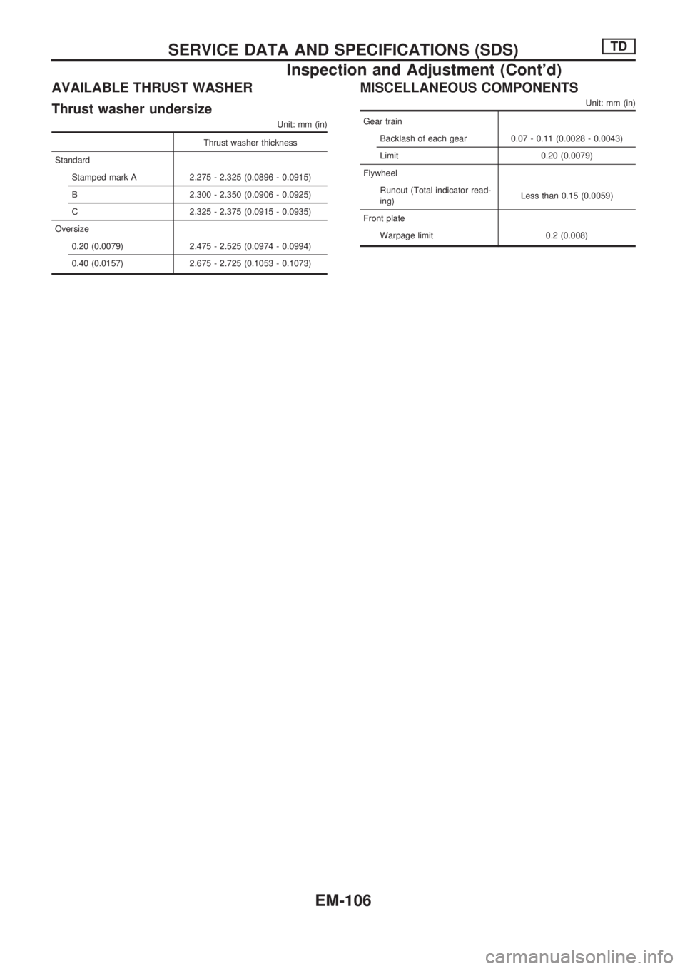
AVAILABLE THRUST WASHER
Thrust washer undersize
Unit: mm (in)
Thrust washer thickness
Standard
Stamped mark A 2.275 - 2.325 (0.0896 - 0.0915)
B 2.300 - 2.350 (0.0906 - 0.0925)
C 2.325 - 2.375 (0.0915 - 0.0935)
Oversize
0.20 (0.0079) 2.475 - 2.525 (0.0974 - 0.0994)
0.40 (0.0157) 2.675 - 2.725 (0.1053 - 0.1073)
MISCELLANEOUS COMPONENTS
Unit: mm (in)
Gear train
Backlash of each gear 0.07 - 0.11 (0.0028 - 0.0043)
Limit 0.20 (0.0079)
Flywheel
Runout (Total indicator read-
ing)Less than 0.15 (0.0059)
Front plate
Warpage limit 0.2 (0.008)
SERVICE DATA AND SPECIFICATIONS (SDS)TD
Inspection and Adjustment (Cont'd)
EM-106
Page 869 of 1659
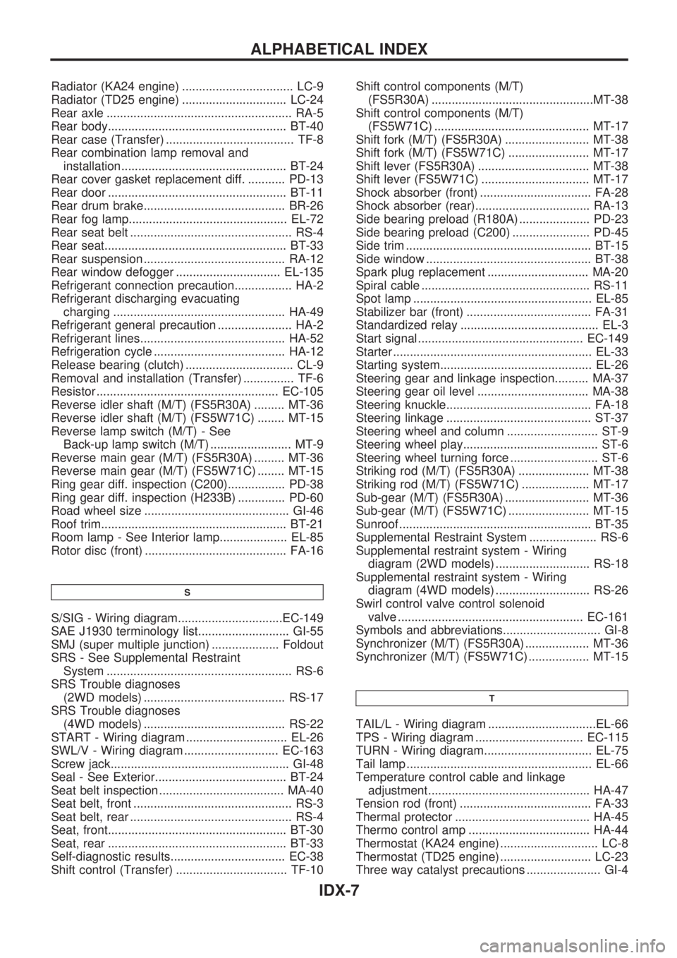
Radiator (KA24 engine) ................................. LC-9
Radiator (TD25 engine) ............................... LC-24
Rear axle ....................................................... RA-5
Rear body..................................................... BT-40
Rear case (Transfer) ...................................... TF-8
Rear combination lamp removal and
installation................................................. BT-24
Rear cover gasket replacement diff. ........... PD-13
Rear door ..................................................... BT-11
Rear drum brake.......................................... BR-26
Rear fog lamp............................................... EL-72
Rear seat belt ................................................ RS-4
Rear seat...................................................... BT-33
Rear suspension .......................................... RA-12
Rear window defogger ............................... EL-135
Refrigerant connection precaution................. HA-2
Refrigerant discharging evacuating
charging ................................................... HA-49
Refrigerant general precaution ...................... HA-2
Refrigerant lines........................................... HA-52
Refrigeration cycle ....................................... HA-12
Release bearing (clutch) ................................ CL-9
Removal and installation (Transfer) ............... TF-6
Resistor ...................................................... EC-105
Reverse idler shaft (M/T) (FS5R30A) ......... MT-36
Reverse idler shaft (M/T) (FS5W71C) ........ MT-15
Reverse lamp switch (M/T) - See
Back-up lamp switch (M/T) ........................ MT-9
Reverse main gear (M/T) (FS5R30A) ......... MT-36
Reverse main gear (M/T) (FS5W71C) ........ MT-15
Ring gear diff. inspection (C200)................. PD-38
Ring gear diff. inspection (H233B) .............. PD-60
Road wheel size ........................................... GI-46
Roof trim....................................................... BT-21
Room lamp - See Interior lamp.................... EL-85
Rotor disc (front) .......................................... FA-16
S
S/SIG - Wiring diagram...............................EC-149
SAE J1930 terminology list........................... GI-55
SMJ (super multiple junction) .................... Foldout
SRS - See Supplemental Restraint
System ....................................................... RS-6
SRS Trouble diagnoses
(2WD models) .......................................... RS-17
SRS Trouble diagnoses
(4WD models) .......................................... RS-22
START - Wiring diagram .............................. EL-26
SWL/V - Wiring diagram ............................ EC-163
Screw jack..................................................... GI-48
Seal - See Exterior....................................... BT-24
Seat belt inspection ..................................... MA-40
Seat belt, front ............................................... RS-3
Seat belt, rear ................................................ RS-4
Seat, front..................................................... BT-30
Seat, rear ..................................................... BT-33
Self-diagnostic results.................................. EC-38
Shift control (Transfer) ................................. TF-10Shift control components (M/T)
(FS5R30A) ................................................MT-38
Shift control components (M/T)
(FS5W71C) .............................................. MT-17
Shift fork (M/T) (FS5R30A) ......................... MT-38
Shift fork (M/T) (FS5W71C) ........................ MT-17
Shift lever (FS5R30A) ................................. MT-38
Shift lever (FS5W71C) ................................ MT-17
Shock absorber (front) ................................. FA-28
Shock absorber (rear).................................. RA-13
Side bearing preload (R180A) ..................... PD-23
Side bearing preload (C200) ....................... PD-45
Side trim ....................................................... BT-15
Side window ................................................. BT-38
Spark plug replacement .............................. MA-20
Spiral cable .................................................. RS-11
Spot lamp ..................................................... EL-85
Stabilizer bar (front) ..................................... FA-31
Standardized relay ......................................... EL-3
Start signal ................................................. EC-149
Starter ........................................................... EL-33
Starting system............................................. EL-26
Steering gear and linkage inspection.......... MA-37
Steering gear oil level ................................. MA-38
Steering knuckle........................................... FA-18
Steering linkage ........................................... ST-37
Steering wheel and column ........................... ST-9
Steering wheel play........................................ ST-6
Steering wheel turning force .......................... ST-6
Striking rod (M/T) (FS5R30A) ..................... MT-38
Striking rod (M/T) (FS5W71C) .................... MT-17
Sub-gear (M/T) (FS5R30A) ......................... MT-36
Sub-gear (M/T) (FS5W71C) ........................ MT-15
Sunroof ......................................................... BT-35
Supplemental Restraint System .................... RS-6
Supplemental restraint system - Wiring
diagram (2WD models) ............................ RS-18
Supplemental restraint system - Wiring
diagram (4WD models) ............................ RS-26
Swirl control valve control solenoid
valve ....................................................... EC-161
Symbols and abbreviations............................. GI-8
Synchronizer (M/T) (FS5R30A) ................... MT-36
Synchronizer (M/T) (FS5W71C) .................. MT-15
T
TAIL/L - Wiring diagram ................................EL-66
TPS - Wiring diagram ................................ EC-115
TURN - Wiring diagram................................ EL-75
Tail lamp ....................................................... EL-66
Temperature control cable and linkage
adjustment................................................ HA-47
Tension rod (front) ....................................... FA-33
Thermal protector ........................................ HA-45
Thermo control amp .................................... HA-44
Thermostat (KA24 engine) ............................. LC-8
Thermostat (TD25 engine) ........................... LC-23
Three way catalyst precautions ...................... GI-4
ALPHABETICAL INDEX
IDX-7
Page 870 of 1659
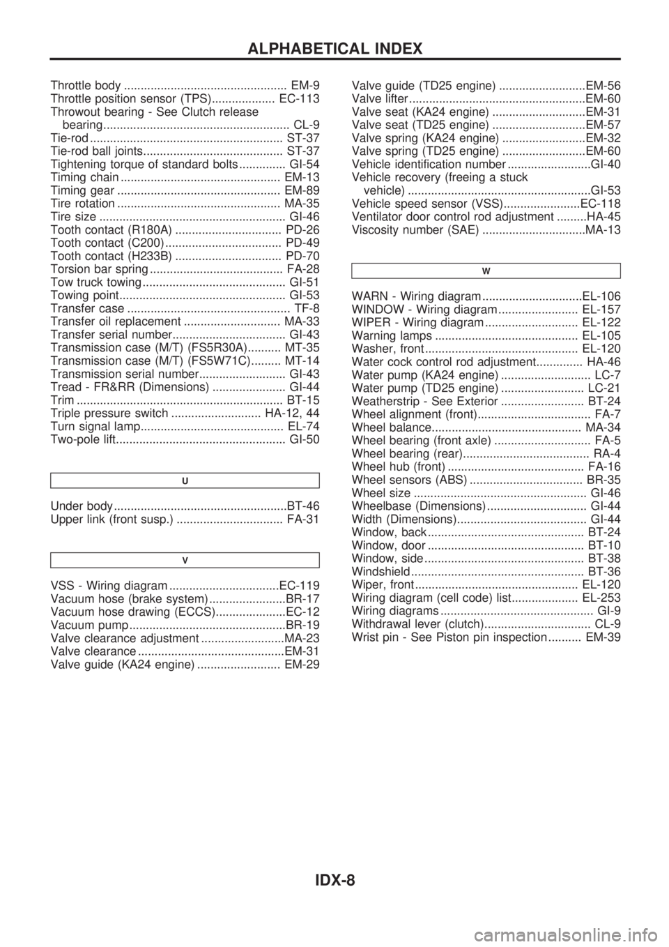
Throttle body ................................................. EM-9
Throttle position sensor (TPS)................... EC-113
Throwout bearing - See Clutch release
bearing........................................................ CL-9
Tie-rod .......................................................... ST-37
Tie-rod ball joints.......................................... ST-37
Tightening torque of standard bolts .............. GI-54
Timing chain ................................................ EM-13
Timing gear ................................................. EM-89
Tire rotation ................................................. MA-35
Tire size ........................................................ GI-46
Tooth contact (R180A) ................................ PD-26
Tooth contact (C200) ................................... PD-49
Tooth contact (H233B) ................................ PD-70
Torsion bar spring ........................................ FA-28
Tow truck towing ........................................... GI-51
Towing point.................................................. GI-53
Transfer case ................................................. TF-8
Transfer oil replacement ............................. MA-33
Transfer serial number.................................. GI-43
Transmission case (M/T) (FS5R30A).......... MT-35
Transmission case (M/T) (FS5W71C)......... MT-14
Transmission serial number.......................... GI-43
Tread - FR&RR (Dimensions) ...................... GI-44
Trim .............................................................. BT-15
Triple pressure switch ........................... HA-12, 44
Turn signal lamp........................................... EL-74
Two-pole lift................................................... GI-50
U
Under body ....................................................BT-46
Upper link (front susp.) ................................ FA-31
V
VSS - Wiring diagram .................................EC-119
Vacuum hose (brake system) .......................BR-17
Vacuum hose drawing (ECCS).....................EC-12
Vacuum pump ...............................................BR-19
Valve clearance adjustment .........................MA-23
Valve clearance ............................................EM-31
Valve guide (KA24 engine) ......................... EM-29Valve guide (TD25 engine) ..........................EM-56
Valve lifter .....................................................EM-60
Valve seat (KA24 engine) ............................EM-31
Valve seat (TD25 engine) ............................EM-57
Valve spring (KA24 engine) .........................EM-32
Valve spring (TD25 engine) .........................EM-60
Vehicle identification number .........................GI-40
Vehicle recovery (freeing a stuck
vehicle) .......................................................GI-53
Vehicle speed sensor (VSS).......................EC-118
Ventilator door control rod adjustment .........HA-45
Viscosity number (SAE) ...............................MA-13
W
WARN - Wiring diagram ..............................EL-106
WINDOW - Wiring diagram ........................ EL-157
WIPER - Wiring diagram ............................ EL-122
Warning lamps ........................................... EL-105
Washer, front .............................................. EL-120
Water cock control rod adjustment.............. HA-46
Water pump (KA24 engine) ........................... LC-7
Water pump (TD25 engine) ......................... LC-21
Weatherstrip - See Exterior ......................... BT-24
Wheel alignment (front).................................. FA-7
Wheel balance............................................. MA-34
Wheel bearing (front axle) ............................. FA-5
Wheel bearing (rear)...................................... RA-4
Wheel hub (front) ......................................... FA-16
Wheel sensors (ABS) .................................. BR-35
Wheel size .................................................... GI-46
Wheelbase (Dimensions) .............................. GI-44
Width (Dimensions)....................................... GI-44
Window, back ............................................... BT-24
Window, door ............................................... BT-10
Window, side ................................................ BT-38
Windshield .................................................... BT-36
Wiper, front ................................................. EL-120
Wiring diagram (cell code) list.................... EL-253
Wiring diagrams .............................................. GI-9
Withdrawal lever (clutch)................................ CL-9
Wrist pin - See Piston pin inspection .......... EM-39
ALPHABETICAL INDEX
IDX-8
Page 970 of 1659
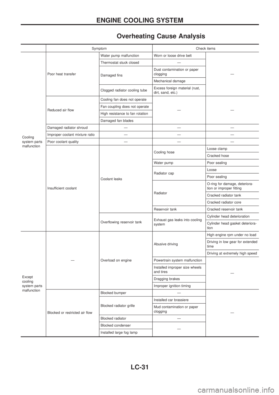
Overheating Cause Analysis
Symptom Check items
Cooling
system parts
malfunctionPoor heat transferWater pump malfunction Worn or loose drive belt
Ð Thermostat stuck closed Ð
Damaged finsDust contamination or paper
clogging
Mechanical damage
Clogged radiator cooling tubeExcess foreign material (rust,
dirt, sand, etc.)
Reduced air flowCooling fan does not operate
ÐÐ Fan coupling does not operate
High resistance to fan rotation
Damaged fan blades
Damaged radiator shroud Ð Ð Ð
Improper coolant mixture ratio Ð Ð Ð
Poor coolant quality Ð Ð Ð
Insufficient coolantCoolant leaksCooling hoseLoose clamp
Cracked hose
Water pump Poor sealing
Radiator capLoose
Poor sealing
RadiatorO-ring for damage, deteriora-
tion or improper fitting
Cracked radiator tank
Cracked radiator core
Reservoir tank Cracked reservoir tank
Overflowing reservoir tankExhaust gas leaks into cooling
systemCylinder head deterioration
Cylinder head gasket deteriora-
tion
Except
cooling
system parts
malfunctionÐ Overload on engineAbusive drivingHigh engine rpm under no load
Driving in low gear for extended
time
Driving at extremely high speed
Powertrain system malfunction
Ð Installed improper size wheels
and tires
Dragging brakes
Improper ignition timing
Blocked or restricted air flowBlocked bumper Ð
Ð Blocked radiator grilleInstalled car brassiere
Mud contamination or paper
clogging
Blocked radiator Ð
Blocked condenser
Ð
Installed large fog lamp
ENGINE COOLING SYSTEM
LC-31
Page 1169 of 1659
Precautions for SRS ``AIR BAG'' Service
lDo not use a circuit tester to check SRS circuits unless instructed to in this Service Manual.
lBefore servicing the SRS, turn ignition switch ``OFF'', disconnect both battery cables and wait for at least
3 minutes.
For approximately 3 minutes after the cables are removed, it is still possible for the air bag to deploy.
Therefore, do not work on any SRS connectors or wires until at least 3 minutes have passed.
lFor 2WD models, do not separate diagnosis sensor unit from steering wheel.
lFor 4WD models, diagnosis sensor unit must always be installed with their arrow marks ``S'' pointing
towards the front of the vehicle for proper operation. Also check diagnosis sensor unit for cracks,
deformities or rust before installation and replace as required.
lThe spiral cable must be aligned with the neutral position since its rotations are limited. Do not attempt
to turn steering wheel or column after removal of steering gear.
lHandle air bag module carefully. Always place it with the pad side facing upward.
lConduct self-diagnosis to check entire SRS for proper function after replacing any components.
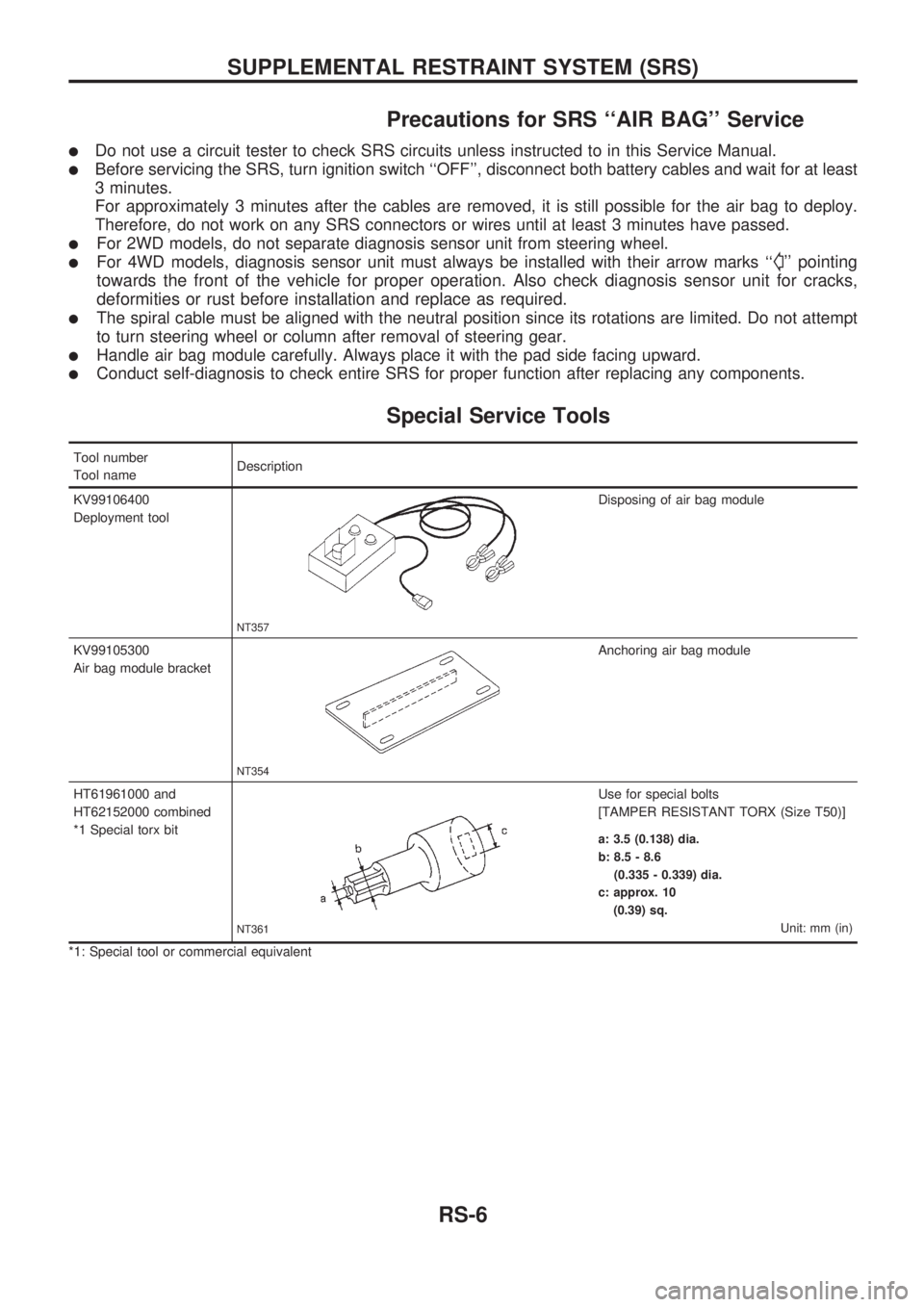
Special Service Tools
Tool number
Tool nameDescription
KV99106400
Deployment tool
NT357
Disposing of air bag module
KV99105300
Air bag module bracket
NT354
Anchoring air bag module
HT61961000 and
HT62152000 combined
*1 Special torx bit
NT361
Use for special bolts
[TAMPER RESISTANT TORX (Size T50)]
a: 3.5 (0.138) dia.
b: 8.5 - 8.6
(0.335 - 0.339) dia.
c: approx. 10
(0.39) sq.
Unit: mm (in)
*1: Special tool or commercial equivalent
SUPPLEMENTAL RESTRAINT SYSTEM (SRS)
RS-6
Page 1175 of 1659
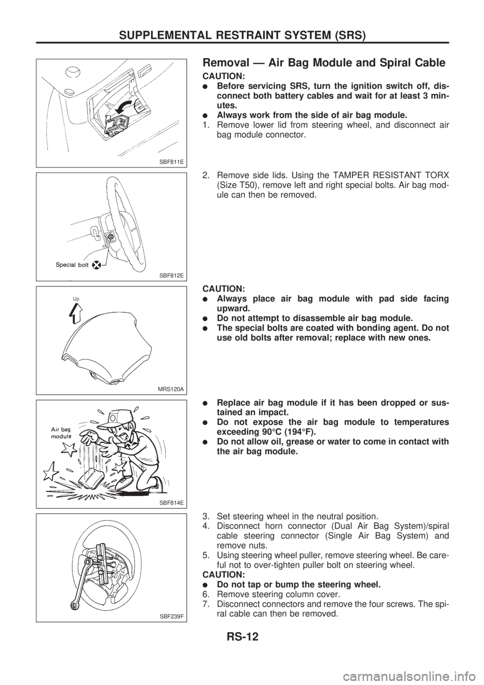
Removal Ð Air Bag Module and Spiral Cable
CAUTION:
lBefore servicing SRS, turn the ignition switch off, dis-
connect both battery cables and wait for at least 3 min-
utes.
lAlways work from the side of air bag module.
1. Remove lower lid from steering wheel, and disconnect air
bag module connector.
2. Remove side lids. Using the TAMPER RESISTANT TORX
(Size T50), remove left and right special bolts. Air bag mod-
ule can then be removed.
CAUTION:
lAlways place air bag module with pad side facing
upward.
lDo not attempt to disassemble air bag module.
lThe special bolts are coated with bonding agent. Do not
use old bolts after removal; replace with new ones.
lReplace air bag module if it has been dropped or sus-
tained an impact.
lDo not expose the air bag module to temperatures
exceeding 90ÉC (194ÉF).
lDo not allow oil, grease or water to come in contact with
the air bag module.
3. Set steering wheel in the neutral position.
4. Disconnect horn connector (Dual Air Bag System)/spiral
cable steering connector (Single Air Bag System) and
remove nuts.
5. Using steering wheel puller, remove steering wheel. Be care-
ful not to over-tighten puller bolt on steering wheel.
CAUTION:
lDo not tap or bump the steering wheel.
6. Remove steering column cover.
7. Disconnect connectors and remove the four screws. The spi-
ral cable can then be removed.
SBF811E
SBF812E
MRS120A
SBF814E
SBF239F
SUPPLEMENTAL RESTRAINT SYSTEM (SRS)
RS-12
Page 1598 of 1659
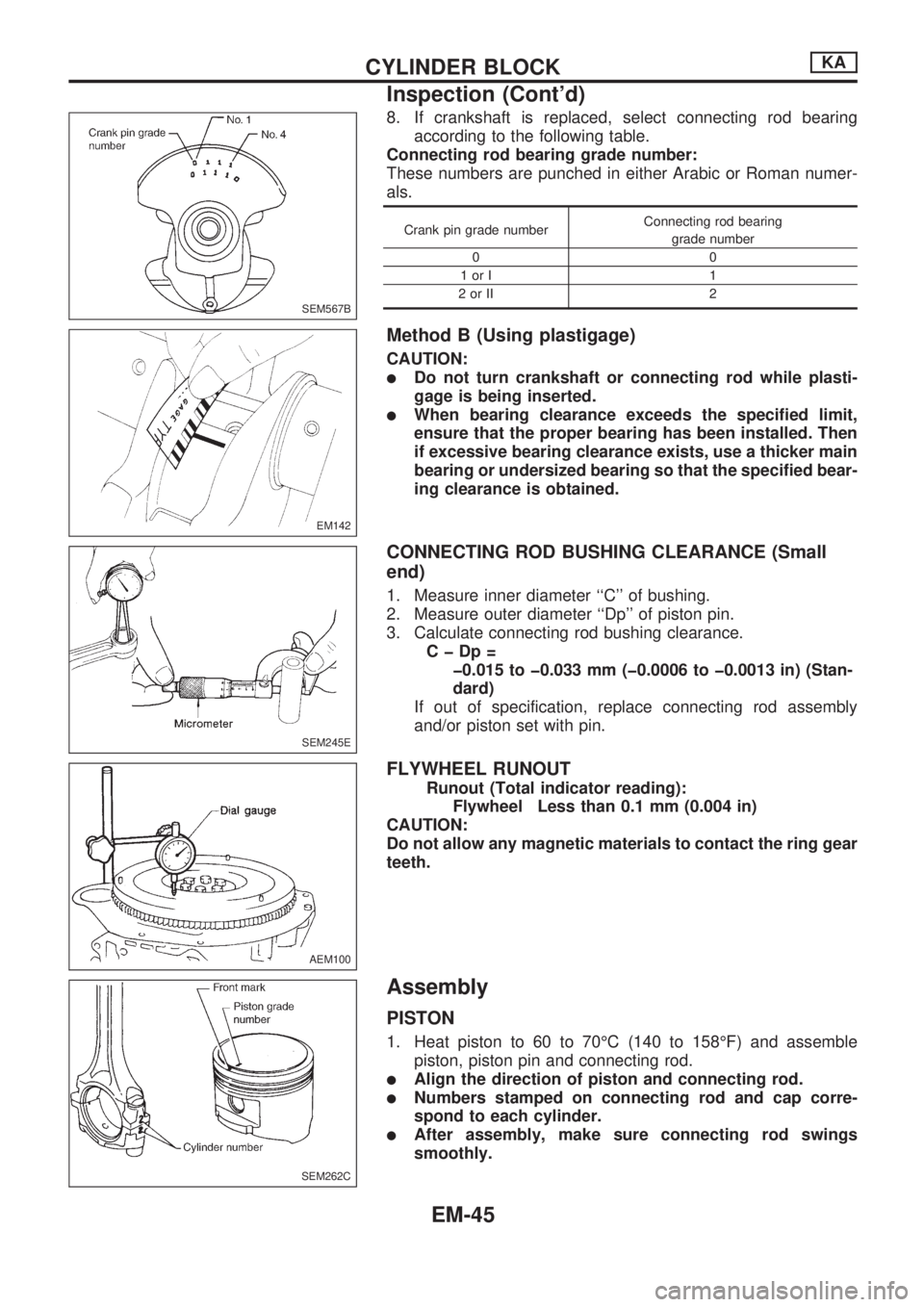
8. If crankshaft is replaced, select connecting rod bearing
according to the following table.
Connecting rod bearing grade number:
These numbers are punched in either Arabic or Roman numer-
als.
Crank pin grade numberConnecting rod bearing
grade number
00
1orI 1
2orII 2
Method B (Using plastigage)
CAUTION:
lDo not turn crankshaft or connecting rod while plasti-
gage is being inserted.
lWhen bearing clearance exceeds the specified limit,
ensure that the proper bearing has been installed. Then
if excessive bearing clearance exists, use a thicker main
bearing or undersized bearing so that the specified bear-
ing clearance is obtained.
CONNECTING ROD BUSHING CLEARANCE (Small
end)
1. Measure inner diameter ``C'' of bushing.
2. Measure outer diameter ``Dp'' of piston pin.
3. Calculate connecting rod bushing clearance.
CþDp=
þ0.015 to þ0.033 mm (þ0.0006 to þ0.0013 in) (Stan-
dard)
If out of specification, replace connecting rod assembly
and/or piston set with pin.
FLYWHEEL RUNOUT
Runout (Total indicator reading):
Flywheel Less than 0.1 mm (0.004 in)
CAUTION:
Do not allow any magnetic materials to contact the ring gear
teeth.
Assembly
PISTON
1. Heat piston to 60 to 70ÉC (140 to 158ÉF) and assemble
piston, piston pin and connecting rod.
lAlign the direction of piston and connecting rod.
lNumbers stamped on connecting rod and cap corre-
spond to each cylinder.
lAfter assembly, make sure connecting rod swings
smoothly.
SEM567B
EM142
SEM245E
AEM100
SEM262C
CYLINDER BLOCKKA
Inspection (Cont'd)
EM-45