fuse NISSAN PICK-UP 1998 Repair Manual
[x] Cancel search | Manufacturer: NISSAN, Model Year: 1998, Model line: PICK-UP, Model: NISSAN PICK-UP 1998Pages: 1659, PDF Size: 53.39 MB
Page 43 of 1659
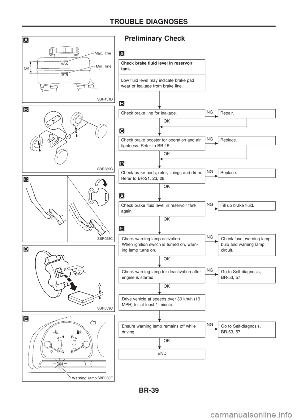
Preliminary Check
Check brake fluid level in reservoir
tank.
-------------------------------------------------------------------------------------------------------------------------------------------------------------------------------------------------------------------------------------------------------------------------------------------------------------
Low fluid level may indicate brake pad
wear or leakage from brake line.
Check brake line for leakage.
OKcNG
Repair.
b
Check brake booster for operation and air
tightness. Refer to BR-15.
OK
cNG
Replace.
b
Check brake pads, rotor, linings and drum.
Refer to BR-21, 23, 28.
OK
cNG
Replace.
Check brake fluid level in reservoir tank
again.
OK
cNG
Fill up brake fluid.
Check warning lamp activation.
When ignition switch is turned on, warn-
ing lamp turns on.
OK
cNG
Check fuse, warning lamp
bulb and warning lamp
circuit.
Check warning lamp for deactivation after
engine is started.
OK
cNG
Go to Self-diagnosis,
BR-53, 57.
Drive vehicle at speeds over 30 km/h (19
MPH) for at least 1 minute.
Ensure warning lamp remains off while
driving.
OK
cNG
Go to Self-diagnosis,
BR-53, 57.
END
SBR451D
SBR389C
SBR058C
SBR059C
SBR069E
.
.
.
.
.
.
.
.
.
TROUBLE DIAGNOSES
BR-39
Page 59 of 1659
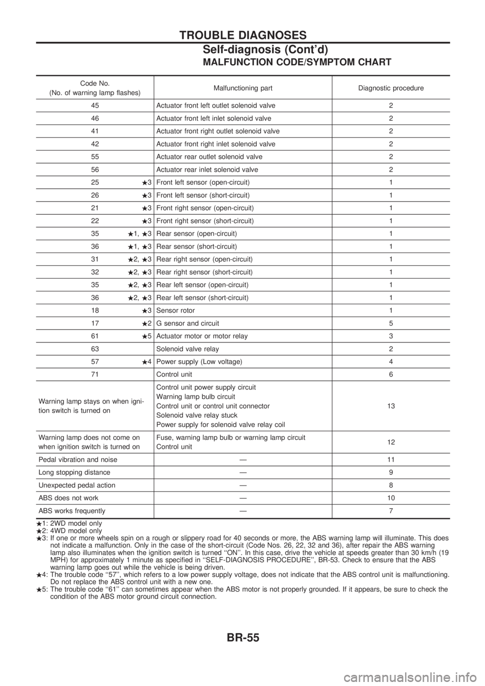
MALFUNCTION CODE/SYMPTOM CHART
Code No.
(No. of warning lamp flashes)Malfunctioning part Diagnostic procedure
45 Actuator front left outlet solenoid valve 2
46 Actuator front left inlet solenoid valve 2
41 Actuator front right outlet solenoid valve 2
42 Actuator front right inlet solenoid valve 2
55 Actuator rear outlet solenoid valve 2
56 Actuator rear inlet solenoid valve 2
25.3 Front left sensor (open-circuit) 1
26.3 Front left sensor (short-circuit) 1
21.3 Front right sensor (open-circuit) 1
22.3 Front right sensor (short-circuit) 1
35.1,.3 Rear sensor (open-circuit) 1
36.1,.3 Rear sensor (short-circuit) 1
31.2,.3 Rear right sensor (open-circuit) 1
32.2,.3 Rear right sensor (short-circuit) 1
35.2,.3 Rear left sensor (open-circuit) 1
36.2,.3 Rear left sensor (short-circuit) 1
18.3 Sensor rotor 1
17.2 G sensor and circuit 5
61.5 Actuator motor or motor relay 3
63 Solenoid valve relay 2
57.4 Power supply (Low voltage) 4
71 Control unit 6
Warning lamp stays on when igni-
tion switch is turned onControl unit power supply circuit
Warning lamp bulb circuit
Control unit or control unit connector
Solenoid valve relay stuck
Power supply for solenoid valve relay coil13
Warning lamp does not come on
when ignition switch is turned onFuse, warning lamp bulb or warning lamp circuit
Control unit12
Pedal vibration and noise Ð 11
Long stopping distance Ð 9
Unexpected pedal action Ð 8
ABS does not work Ð 10
ABS works frequently Ð 7
.1: 2WD model only
.2: 4WD model only
.3: If one or more wheels spin on a rough or slippery road for 40 seconds or more, the ABS warning lamp will illuminate. This does
not indicate a malfunction. Only in the case of the short-circuit (Code Nos. 26, 22, 32 and 36), after repair the ABS warning
lamp also illuminates when the ignition switch is turned ``ON''. In this case, drive the vehicle at speeds greater than 30 km/h (19
MPH) for approximately 1 minute as specified in ``SELF-DIAGNOSIS PROCEDURE'', BR-53. Check to ensure that the ABS
warning lamp goes out while the vehicle is being driven.
.4: The trouble code ``57'', which refers to a low power supply voltage, does not indicate that the ABS control unit is malfunctioning.
Do not replace the ABS control unit with a new one.
.5: The trouble code ``61'' can sometimes appear when the ABS motor is not properly grounded. If it appears, be sure to check the
condition of the ABS motor ground circuit connection.
TROUBLE DIAGNOSES
Self-diagnosis (Cont'd)
BR-55
Page 69 of 1659
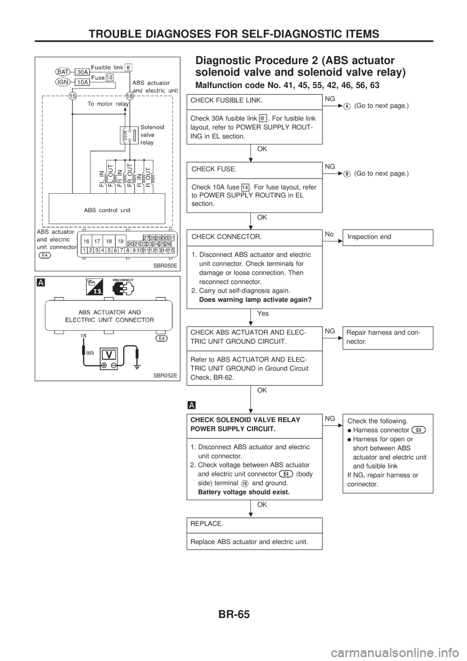
Diagnostic Procedure 2 (ABS actuator
solenoid valve and solenoid valve relay)
Malfunction code No. 41, 45, 55, 42, 46, 56, 63
CHECK FUSIBLE LINK.
-------------------------------------------------------------------------------------------------------------------------------------------------------------------------------------------------------------------------------------------------------------------------------------------------------------
Check 30A fusible link
e
. For fusible link
layout, refer to POWER SUPPLY ROUT-
ING in EL section.
OK
cNG
VA(Go to next page.)
CHECK FUSE.
-------------------------------------------------------------------------------------------------------------------------------------------------------------------------------------------------------------------------------------------------------------------------------------------------------------
Check 10A fuse
14. For fuse layout, refer
to POWER SUPPLY ROUTING in EL
section.
OK
cNG
VB(Go to next page.)
CHECK CONNECTOR.
-------------------------------------------------------------------------------------------------------------------------------------------------------------------------------------------------------------------------------------------------------------------------------------------------------------
1. Disconnect ABS actuator and electric
unit connector. Check terminals for
damage or loose connection. Then
reconnect connector.
2. Carry out self-diagnosis again.
Does warning lamp activate again?
Yes
cNo
Inspection end
CHECK ABS ACTUATOR AND ELEC-
TRIC UNIT GROUND CIRCUIT.
-------------------------------------------------------------------------------------------------------------------------------------------------------------------------------------------------------------------------------------------------------------------------------------------------------------
Refer to ABS ACTUATOR AND ELEC-
TRIC UNIT GROUND in Ground Circuit
Check, BR-62.
OK
cNG
Repair harness and con-
nector.
CHECK SOLENOID VALVE RELAY
POWER SUPPLY CIRCUIT.
-------------------------------------------------------------------------------------------------------------------------------------------------------------------------------------------------------------------------------------------------------------------------------------------------------------
1. Disconnect ABS actuator and electric
unit connector.
2. Check voltage between ABS actuator
and electric unit connector
E4(body
side) terminal
V18and ground.
Battery voltage should exist.
OK
cNG
Check the following.
lHarness connectorE4
lHarness for open or
short between ABS
actuator and electric unit
and fusible link
If NG, repair harness or
connector.
REPLACE.
-------------------------------------------------------------------------------------------------------------------------------------------------------------------------------------------------------------------------------------------------------------------------------------------------------------
Replace ABS actuator and electric unit.
SBR050E
SBR052E
.
.
.
.
.
TROUBLE DIAGNOSES FOR SELF-DIAGNOSTIC ITEMS
BR-65
Page 70 of 1659
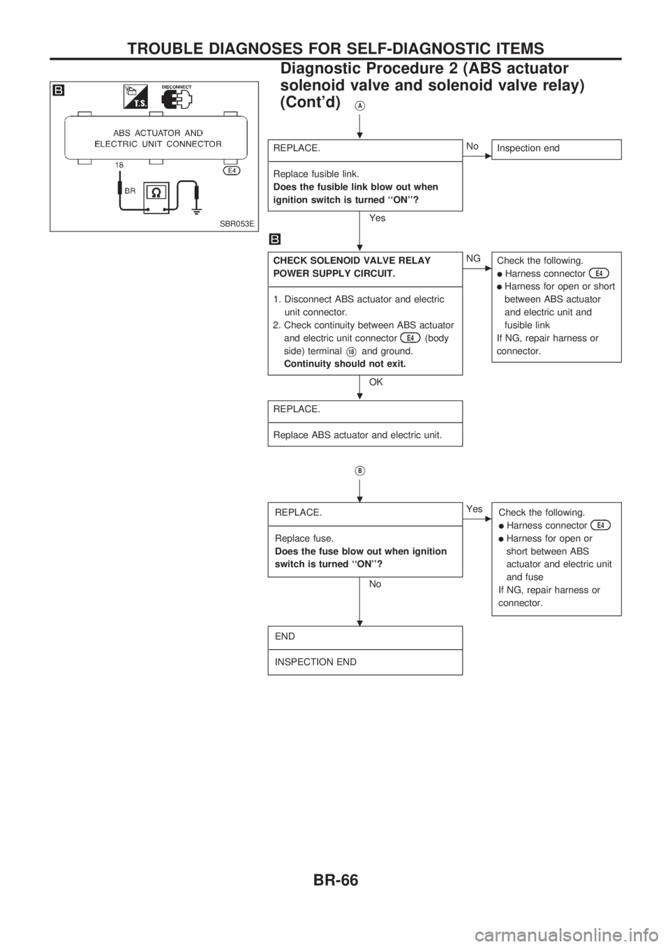
VA
REPLACE.
-------------------------------------------------------------------------------------------------------------------------------------------------------------------------------------------------------------------------------------------------------------------------------------------------------------
Replace fusible link.
Does the fusible link blow out when
ignition switch is turned ``ON''?
Yes
cNo
Inspection end
CHECK SOLENOID VALVE RELAY
POWER SUPPLY CIRCUIT.
-------------------------------------------------------------------------------------------------------------------------------------------------------------------------------------------------------------------------------------------------------------------------------------------------------------
1. Disconnect ABS actuator and electric
unit connector.
2. Check continuity between ABS actuator
and electric unit connector
E4(body
side) terminal
V18and ground.
Continuity should not exit.
OK
cNG
Check the following.
lHarness connectorE4
lHarness for open or short
between ABS actuator
and electric unit and
fusible link
If NG, repair harness or
connector.
REPLACE.
-------------------------------------------------------------------------------------------------------------------------------------------------------------------------------------------------------------------------------------------------------------------------------------------------------------
Replace ABS actuator and electric unit.
VB
REPLACE.
-------------------------------------------------------------------------------------------------------------------------------------------------------------------------------------------------------------------------------------------------------------------------------------------------------------
Replace fuse.
Does the fuse blow out when ignition
switch is turned ``ON''?
No
cYes
Check the following.
lHarness connectorE4
lHarness for open or
short between ABS
actuator and electric unit
and fuse
If NG, repair harness or
connector.
END
-------------------------------------------------------------------------------------------------------------------------------------------------------------------------------------------------------------------------------------------------------------------------------------------------------------
INSPECTION END
SBR053E
.
.
.
.
.
TROUBLE DIAGNOSES FOR SELF-DIAGNOSTIC ITEMS
Diagnostic Procedure 2 (ABS actuator
solenoid valve and solenoid valve relay)
(Cont'd)
BR-66
Page 73 of 1659
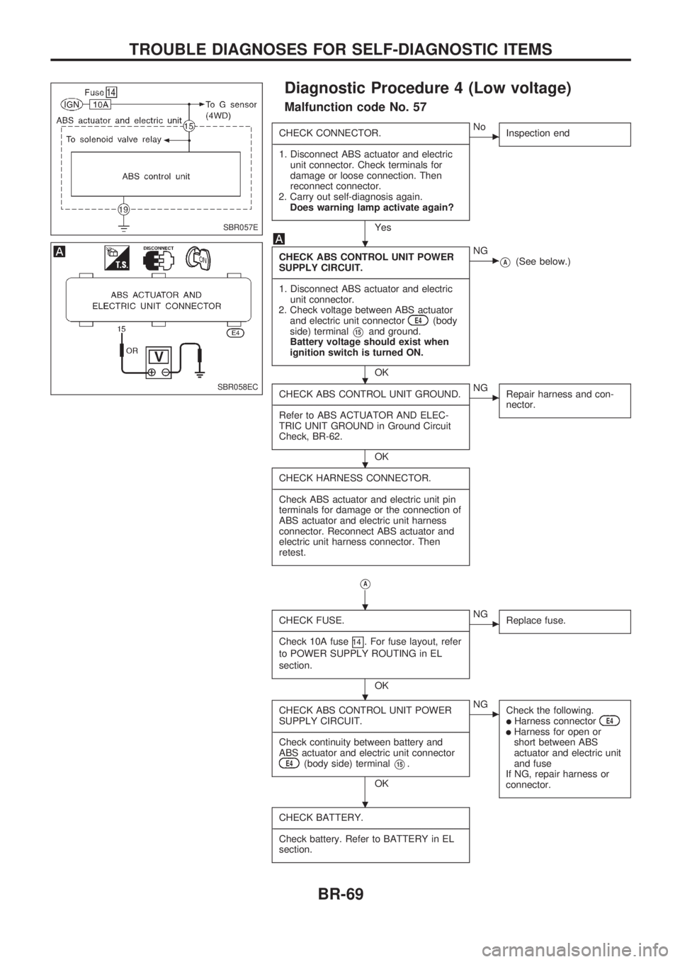
Diagnostic Procedure 4 (Low voltage)
Malfunction code No. 57
CHECK CONNECTOR.
-------------------------------------------------------------------------------------------------------------------------------------------------------------------------------------------------------------------------------------------------------------------------------------------------------------
1. Disconnect ABS actuator and electric
unit connector. Check terminals for
damage or loose connection. Then
reconnect connector.
2. Carry out self-diagnosis again.
Does warning lamp activate again?
Yes
cNo
Inspection end
CHECK ABS CONTROL UNIT POWER
SUPPLY CIRCUIT.
-------------------------------------------------------------------------------------------------------------------------------------------------------------------------------------------------------------------------------------------------------------------------------------------------------------
1. Disconnect ABS actuator and electric
unit connector.
2. Check voltage between ABS actuator
and electric unit connector
E4(body
side) terminal
V15and ground.
Battery voltage should exist when
ignition switch is turned ON.
OK
cNG
VA(See below.)
CHECK ABS CONTROL UNIT GROUND.
-------------------------------------------------------------------------------------------------------------------------------------------------------------------------------------------------------------------------------------------------------------------------------------------------------------
Refer to ABS ACTUATOR AND ELEC-
TRIC UNIT GROUND in Ground Circuit
Check, BR-62.
OK
cNG
Repair harness and con-
nector.
CHECK HARNESS CONNECTOR.
-------------------------------------------------------------------------------------------------------------------------------------------------------------------------------------------------------------------------------------------------------------------------------------------------------------
Check ABS actuator and electric unit pin
terminals for damage or the connection of
ABS actuator and electric unit harness
connector. Reconnect ABS actuator and
electric unit harness connector. Then
retest.
VA
CHECK FUSE.
-------------------------------------------------------------------------------------------------------------------------------------------------------------------------------------------------------------------------------------------------------------------------------------------------------------
Check 10A fuse
14. For fuse layout, refer
to POWER SUPPLY ROUTING in EL
section.
OK
cNG
Replace fuse.
CHECK ABS CONTROL UNIT POWER
SUPPLY CIRCUIT.
-------------------------------------------------------------------------------------------------------------------------------------------------------------------------------------------------------------------------------------------------------------------------------------------------------------
Check continuity between battery and
ABS actuator and electric unit connector
E4(body side) terminalV15.
OK
cNG
Check the following.
lHarness connectorE4lHarness for open or
short between ABS
actuator and electric unit
and fuse
If NG, repair harness or
connector.
CHECK BATTERY.
-------------------------------------------------------------------------------------------------------------------------------------------------------------------------------------------------------------------------------------------------------------------------------------------------------------
Check battery. Refer to BATTERY in EL
section.
SBR057E
SBR058EC
.
.
.
.
.
.
TROUBLE DIAGNOSES FOR SELF-DIAGNOSTIC ITEMS
BR-69
Page 74 of 1659
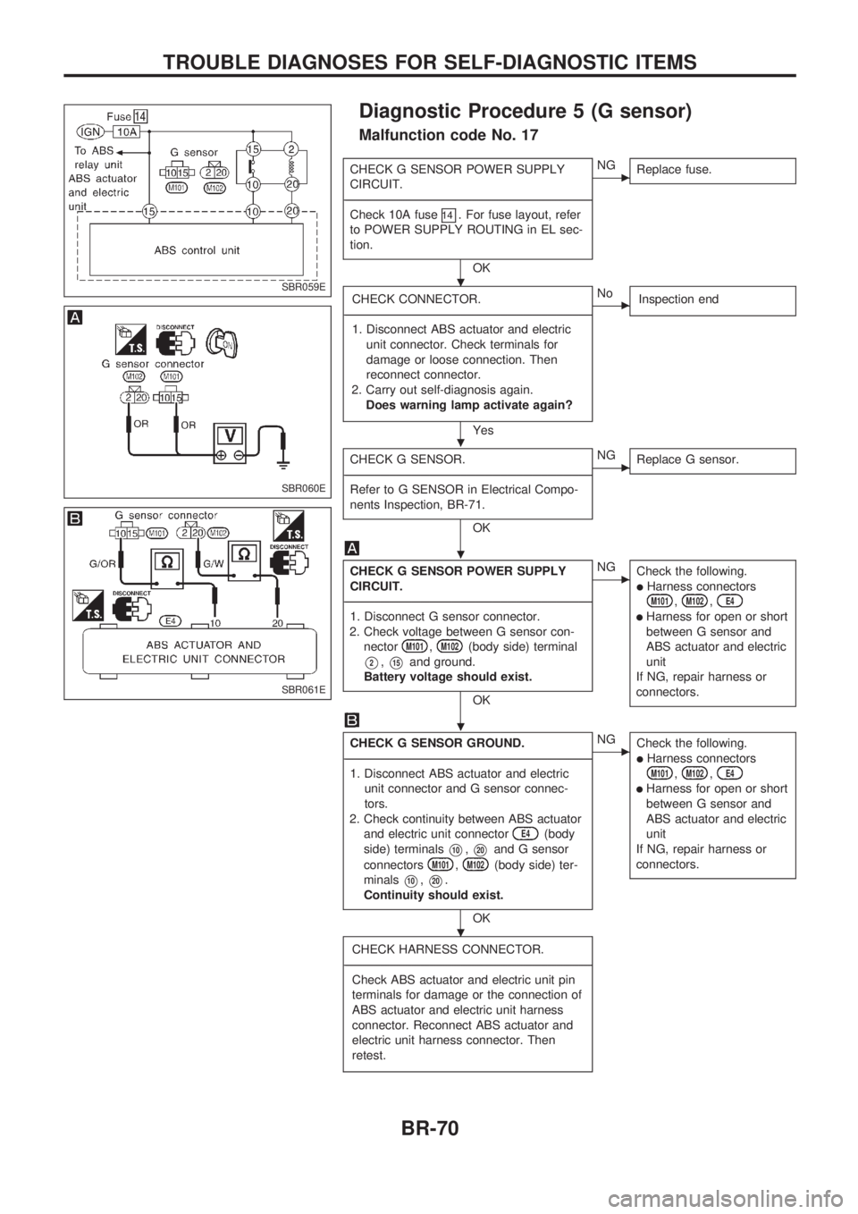
Diagnostic Procedure 5 (G sensor)
Malfunction code No. 17
CHECK G SENSOR POWER SUPPLY
CIRCUIT.
-------------------------------------------------------------------------------------------------------------------------------------------------------------------------------------------------------------------------------------------------------------------------------------------------------------
Check 10A fuse
14. For fuse layout, refer
to POWER SUPPLY ROUTING in EL sec-
tion.
OK
cNG
Replace fuse.
CHECK CONNECTOR.
-------------------------------------------------------------------------------------------------------------------------------------------------------------------------------------------------------------------------------------------------------------------------------------------------------------
1. Disconnect ABS actuator and electric
unit connector. Check terminals for
damage or loose connection. Then
reconnect connector.
2. Carry out self-diagnosis again.
Does warning lamp activate again?
Yes
cNo
Inspection end
CHECK G SENSOR.
-------------------------------------------------------------------------------------------------------------------------------------------------------------------------------------------------------------------------------------------------------------------------------------------------------------
Refer to G SENSOR in Electrical Compo-
nents Inspection, BR-71.
OK
cNG
Replace G sensor.
CHECK G SENSOR POWER SUPPLY
CIRCUIT.
-------------------------------------------------------------------------------------------------------------------------------------------------------------------------------------------------------------------------------------------------------------------------------------------------------------
1. Disconnect G sensor connector.
2. Check voltage between G sensor con-
nector
M101,M102(body side) terminal
V2,V15and ground.
Battery voltage should exist.
OK
cNG
Check the following.
lHarness connectorsM101,M102,E4
lHarness for open or short
between G sensor and
ABS actuator and electric
unit
If NG, repair harness or
connectors.
CHECK G SENSOR GROUND.
-------------------------------------------------------------------------------------------------------------------------------------------------------------------------------------------------------------------------------------------------------------------------------------------------------------
1. Disconnect ABS actuator and electric
unit connector and G sensor connec-
tors.
2. Check continuity between ABS actuator
and electric unit connector
E4(body
side) terminals
V10,V20and G sensor
connectors
M101,M102(body side) ter-
minals
V10,V20.
Continuity should exist.
OK
cNG
Check the following.
lHarness connectorsM101,M102,E4
lHarness for open or short
between G sensor and
ABS actuator and electric
unit
If NG, repair harness or
connectors.
CHECK HARNESS CONNECTOR.
-------------------------------------------------------------------------------------------------------------------------------------------------------------------------------------------------------------------------------------------------------------------------------------------------------------
Check ABS actuator and electric unit pin
terminals for damage or the connection of
ABS actuator and electric unit harness
connector. Reconnect ABS actuator and
electric unit harness connector. Then
retest.
SBR059E
SBR060E
SBR061E
.
.
.
.
.
TROUBLE DIAGNOSES FOR SELF-DIAGNOSTIC ITEMS
BR-70
Page 79 of 1659
Note: ABS may operate and cause vibration under any of the
following conditions.
lApplying brake gradually when shifting or operating
clutch.
lLow friction (slippery) road.
lHigh speed cornering.
lDriving over bumps and pot holes.
lEngine speed is over 5,000 rpm with vehicle stopped.
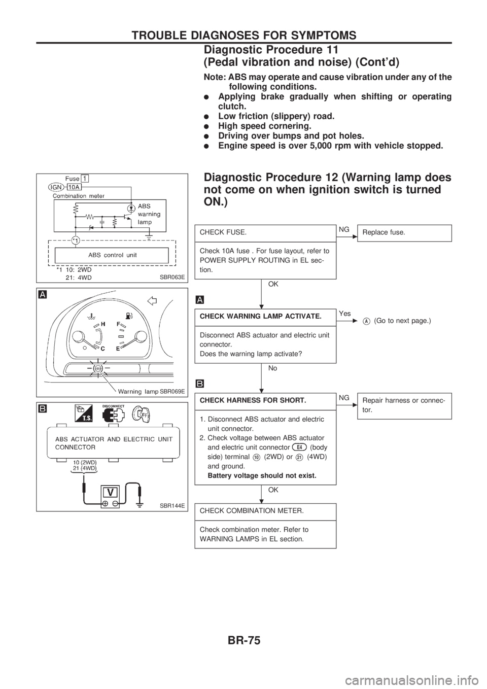
Diagnostic Procedure 12 (Warning lamp does
not come on when ignition switch is turned
ON.)
CHECK FUSE.
-------------------------------------------------------------------------------------------------------------------------------------------------------------------------------------------------------------------------------------------------------------------------------------------------------------
Check 10A fuse . For fuse layout, refer to
POWER SUPPLY ROUTING in EL sec-
tion.
OK
cNG
Replace fuse.
CHECK WARNING LAMP ACTIVATE.
-------------------------------------------------------------------------------------------------------------------------------------------------------------------------------------------------------------------------------------------------------------------------------------------------------------
Disconnect ABS actuator and electric unit
connector.
Does the warning lamp activate?
No
cYes
VA(Go to next page.)
CHECK HARNESS FOR SHORT.
-------------------------------------------------------------------------------------------------------------------------------------------------------------------------------------------------------------------------------------------------------------------------------------------------------------
1. Disconnect ABS actuator and electric
unit connector.
2. Check voltage between ABS actuator
and electric unit connector
E4(body
side) terminal
V10(2WD) orV21(4WD)
and ground.
Battery voltage should not exist.
OK
cNG
Repair harness or connec-
tor.
CHECK COMBINATION METER.
-------------------------------------------------------------------------------------------------------------------------------------------------------------------------------------------------------------------------------------------------------------------------------------------------------------
Check combination meter. Refer to
WARNING LAMPS in EL section.
SBR063E
SBR069E
SBR144E
.
.
.
TROUBLE DIAGNOSES FOR SYMPTOMS
Diagnostic Procedure 11
(Pedal vibration and noise) (Cont'd)
BR-75
Page 81 of 1659
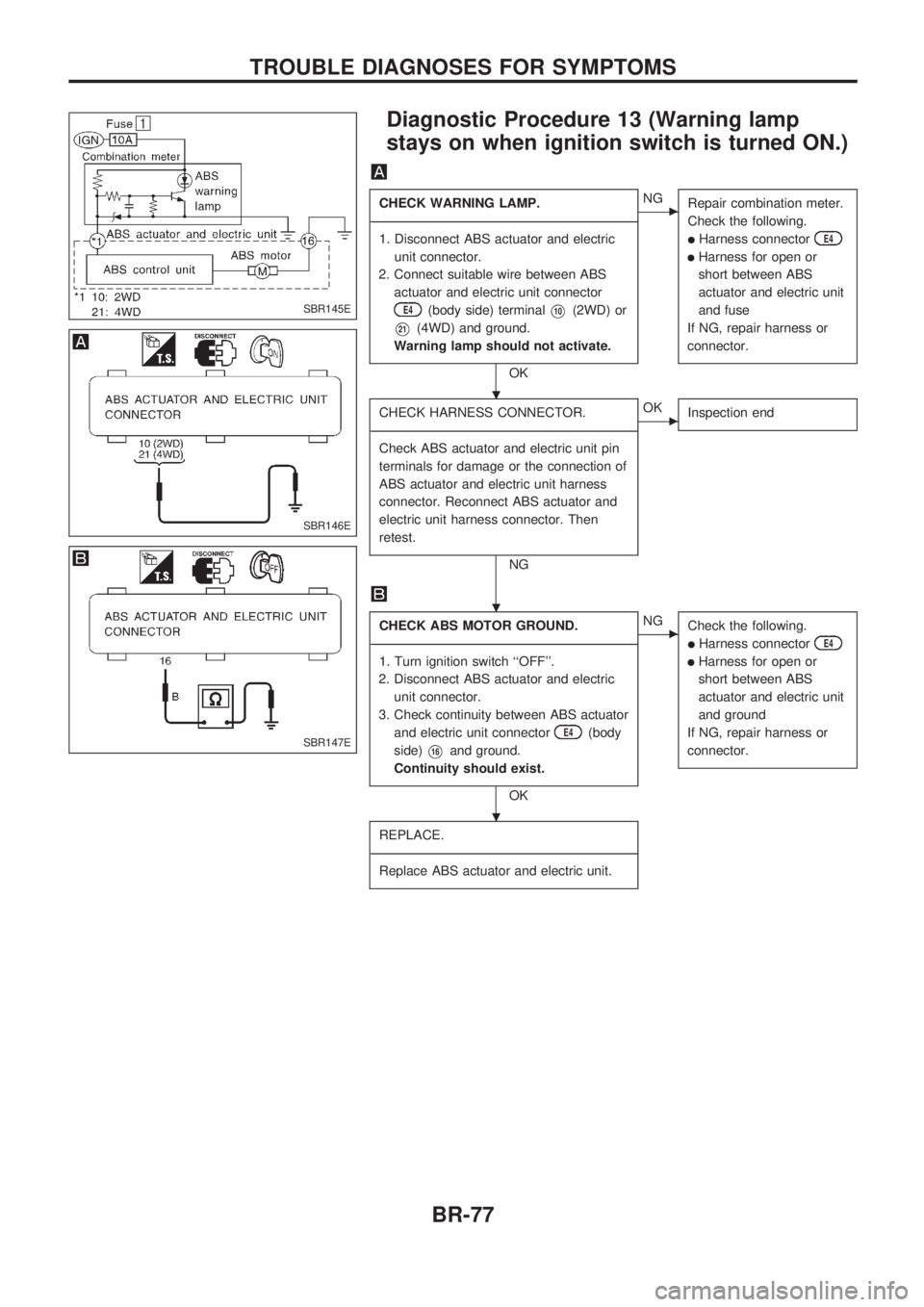
Diagnostic Procedure 13 (Warning lamp
stays on when ignition switch is turned ON.)
CHECK WARNING LAMP.
-------------------------------------------------------------------------------------------------------------------------------------------------------------------------------------------------------------------------------------------------------------------------------------------------------------
1. Disconnect ABS actuator and electric
unit connector.
2. Connect suitable wire between ABS
actuator and electric unit connector
E4(body side) terminalV10(2WD) or
V21(4WD) and ground.
Warning lamp should not activate.
OK
cNG
Repair combination meter.
Check the following.
lHarness connectorE4
lHarness for open or
short between ABS
actuator and electric unit
and fuse
If NG, repair harness or
connector.
CHECK HARNESS CONNECTOR.
-------------------------------------------------------------------------------------------------------------------------------------------------------------------------------------------------------------------------------------------------------------------------------------------------------------
Check ABS actuator and electric unit pin
terminals for damage or the connection of
ABS actuator and electric unit harness
connector. Reconnect ABS actuator and
electric unit harness connector. Then
retest.
NG
cOK
Inspection end
CHECK ABS MOTOR GROUND.
-------------------------------------------------------------------------------------------------------------------------------------------------------------------------------------------------------------------------------------------------------------------------------------------------------------
1. Turn ignition switch ``OFF''.
2. Disconnect ABS actuator and electric
unit connector.
3. Check continuity between ABS actuator
and electric unit connector
E4(body
side)
V16and ground.
Continuity should exist.
OK
cNG
Check the following.
lHarness connectorE4
lHarness for open or
short between ABS
actuator and electric unit
and ground
If NG, repair harness or
connector.
REPLACE.
-------------------------------------------------------------------------------------------------------------------------------------------------------------------------------------------------------------------------------------------------------------------------------------------------------------
Replace ABS actuator and electric unit.
SBR145E
SBR146E
SBR147E
.
.
.
TROUBLE DIAGNOSES FOR SYMPTOMS
BR-77
Page 174 of 1659
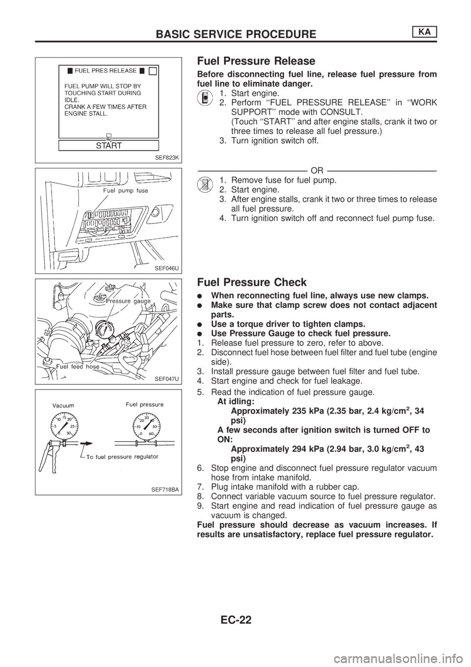
Fuel Pressure Release
Before disconnecting fuel line, release fuel pressure from
fuel line to eliminate danger.
1. Start engine.
2. Perform ``FUEL PRESSURE RELEASE'' in ``WORK
SUPPORT'' mode with CONSULT.
(Touch ``START'' and after engine stalls, crank it two or
three times to release all fuel pressure.)
3. Turn ignition switch off.
-------------------------------------------------------------------------------------------------------------------------------------------------------------------------------------------------------------------------------------------------OR-------------------------------------------------------------------------------------------------------------------------------------------------------------------------------------------------------------------------------------------------
1. Remove fuse for fuel pump.
2. Start engine.
3. After engine stalls, crank it two or three times to release
all fuel pressure.
4. Turn ignition switch off and reconnect fuel pump fuse.
Fuel Pressure Check
lWhen reconnecting fuel line, always use new clamps.
lMake sure that clamp screw does not contact adjacent
parts.
lUse a torque driver to tighten clamps.
lUse Pressure Gauge to check fuel pressure.
1. Release fuel pressure to zero, refer to above.
2. Disconnect fuel hose between fuel filter and fuel tube (engine
side).
3. Install pressure gauge between fuel filter and fuel tube.
4. Start engine and check for fuel leakage.
5. Read the indication of fuel pressure gauge.
At idling:
Approximately 235 kPa (2.35 bar, 2.4 kg/cm
2,34
psi)
A few seconds after ignition switch is turned OFF to
ON:
Approximately 294 kPa (2.94 bar, 3.0 kg/cm
2,43
psi)
6. Stop engine and disconnect fuel pressure regulator vacuum
hose from intake manifold.
7. Plug intake manifold with a rubber cap.
8. Connect variable vacuum source to fuel pressure regulator.
9. Start engine and read indication of fuel pressure gauge as
vacuum is changed.
Fuel pressure should decrease as vacuum increases. If
results are unsatisfactory, replace fuel pressure regulator.
SEF823K
SEF046U
SEF047U
SEF718BA
BASIC SERVICE PROCEDUREKA
EC-22
Page 177 of 1659
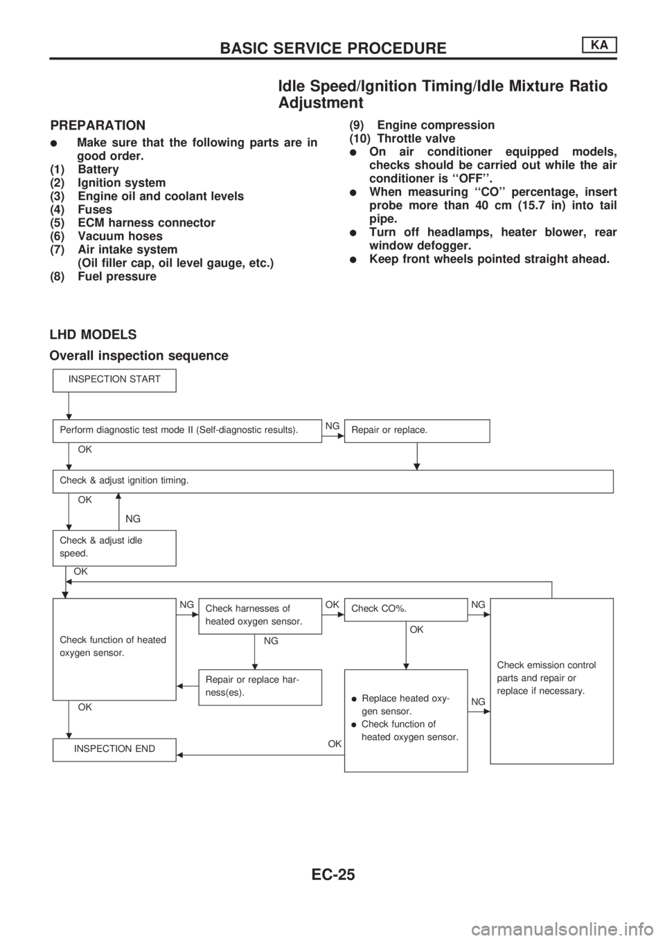
Idle Speed/Ignition Timing/Idle Mixture Ratio
Adjustment
PREPARATION
lMake sure that the following parts are in
good order.
(1) Battery
(2) Ignition system
(3) Engine oil and coolant levels
(4) Fuses
(5) ECM harness connector
(6) Vacuum hoses
(7) Air intake system
(Oil filler cap, oil level gauge, etc.)
(8) Fuel pressure(9) Engine compression
(10) Throttle valvelOn air conditioner equipped models,
checks should be carried out while the air
conditioner is ``OFF''.
lWhen measuring ``CO'' percentage, insert
probe more than 40 cm (15.7 in) into tail
pipe.
lTurn off headlamps, heater blower, rear
window defogger.
lKeep front wheels pointed straight ahead.
LHD MODELS
Overall inspection sequence
INSPECTION START
Perform diagnostic test mode II (Self-diagnostic results).
OK
cNG
Repair or replace.
.
Check & adjust ignition timing.
OKm
NG
Check & adjust idle
speed.
.
OKb
Check function of heated
oxygen sensor.
OK
cNG
Check harnesses of
heated oxygen sensor.
NG
cOK
Check CO%.
OK
.
cNG
Check emission control
parts and repair or
replace if necessary.
bRepair or replace har-
ness(es).
lReplace heated oxy-
gen sensor.
lCheck function of
heated oxygen sensor.
cNG
INSPECTION END
bOK
.
.
.
.
.
BASIC SERVICE PROCEDUREKA
EC-25