brake NISSAN PICK-UP 1998 User Guide
[x] Cancel search | Manufacturer: NISSAN, Model Year: 1998, Model line: PICK-UP, Model: NISSAN PICK-UP 1998Pages: 1659, PDF Size: 53.39 MB
Page 14 of 1659

Removal and Installation
SBR969DA
BRAKE PEDAL AND BRACKET
BR-10
Page 15 of 1659

Inspection
Check brake pedal for following items:
lBrake pedal bend
lClevis pin deformation
lCrack of any welded portion
lCrack or deformation of clevis pin stopper
Adjustment
Check brake pedal free height from melt sheet.
H: Free height
Refer to SDS, BR-80.
D: Depressed height
Refer to SDS, BR-80.
Under force of 490 N (50 kg, 110 lb)
with engine running
C: Clearance between pedal stopper and
threaded end of stop lamp switch
0.3 - 1.0 mm (0.012 - 0.039 in)
A: Pedal free play at clevis
1-3mm(0.04 - 0.12 in)
If necessary, adjust brake pedal free height.
1. Loosen lock nut and adjust pedal free height by turning brake
booster input rod. Then tighten lock nut.
lMake sure that the tip of input rod stays inside.
2. Loosen lock nut and adjust clearance ``C'' with stop lamp
switch respectively. Then tighten lock nuts.
3. Check pedal free play.
lMake sure that stop lamp is off when pedal is released.
4. Check brake pedal's depressed height while engine is run-
ning. If lower than specification, check for leaks, air in
system, or damage to components (master cylinder, wheel
cylinder, etc.). Then make necessary repairs.
SBR997
SBR278AB
SBR930
BRAKE PEDAL AND BRACKET
BR-11
Page 16 of 1659
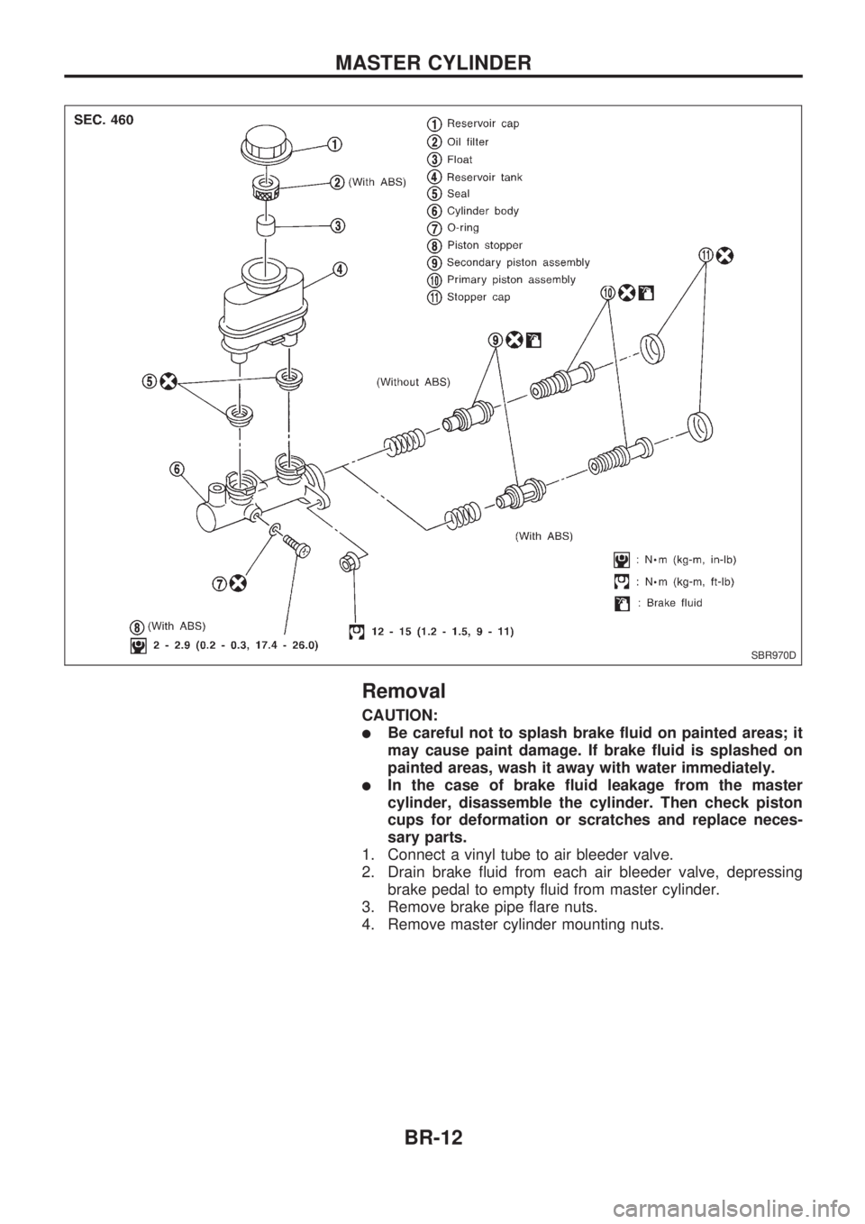
Removal
CAUTION:
lBe careful not to splash brake fluid on painted areas; it
may cause paint damage. If brake fluid is splashed on
painted areas, wash it away with water immediately.
lIn the case of brake fluid leakage from the master
cylinder, disassemble the cylinder. Then check piston
cups for deformation or scratches and replace neces-
sary parts.
1. Connect a vinyl tube to air bleeder valve.
2. Drain brake fluid from each air bleeder valve, depressing
brake pedal to empty fluid from master cylinder.
3. Remove brake pipe flare nuts.
4. Remove master cylinder mounting nuts.
SBR970D
MASTER CYLINDER
BR-12
Page 18 of 1659
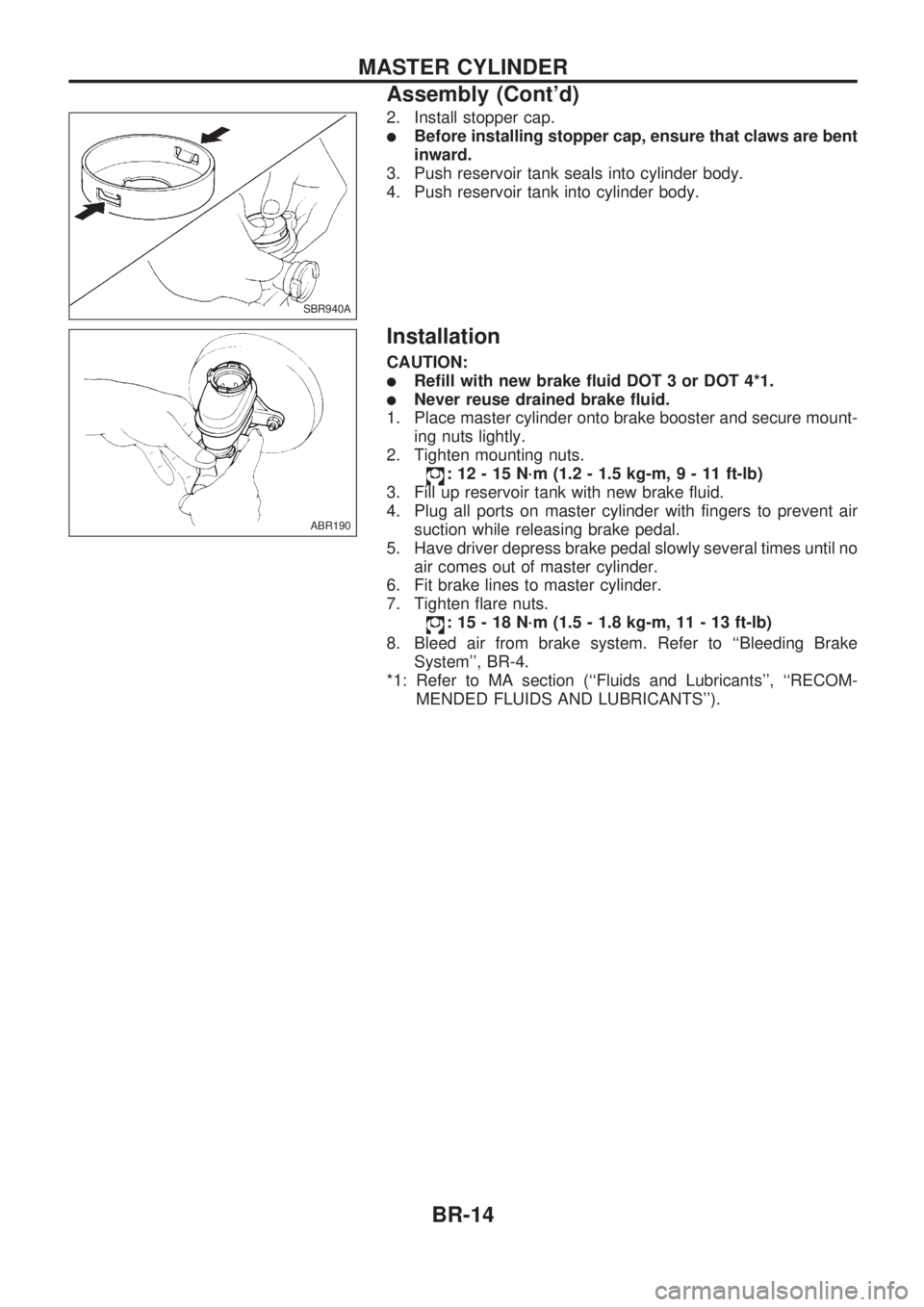
2. Install stopper cap.
lBefore installing stopper cap, ensure that claws are bent
inward.
3. Push reservoir tank seals into cylinder body.
4. Push reservoir tank into cylinder body.
Installation
CAUTION:
lRefill with new brake fluid DOT 3 or DOT 4*1.
lNever reuse drained brake fluid.
1. Place master cylinder onto brake booster and secure mount-
ing nuts lightly.
2. Tighten mounting nuts.
: 12 - 15 N´m (1.2 - 1.5 kg-m,9-11ft-lb)
3. Fill up reservoir tank with new brake fluid.
4. Plug all ports on master cylinder with fingers to prevent air
suction while releasing brake pedal.
5. Have driver depress brake pedal slowly several times until no
air comes out of master cylinder.
6. Fit brake lines to master cylinder.
7. Tighten flare nuts.
: 15 - 18 N´m (1.5 - 1.8 kg-m, 11 - 13 ft-lb)
8. Bleed air from brake system. Refer to ``Bleeding Brake
System'', BR-4.
*1: Refer to MA section (``Fluids and Lubricants'', ``RECOM-
MENDED FLUIDS AND LUBRICANTS'').
SBR940A
ABR190
MASTER CYLINDER
Assembly (Cont'd)
BR-14
Page 19 of 1659
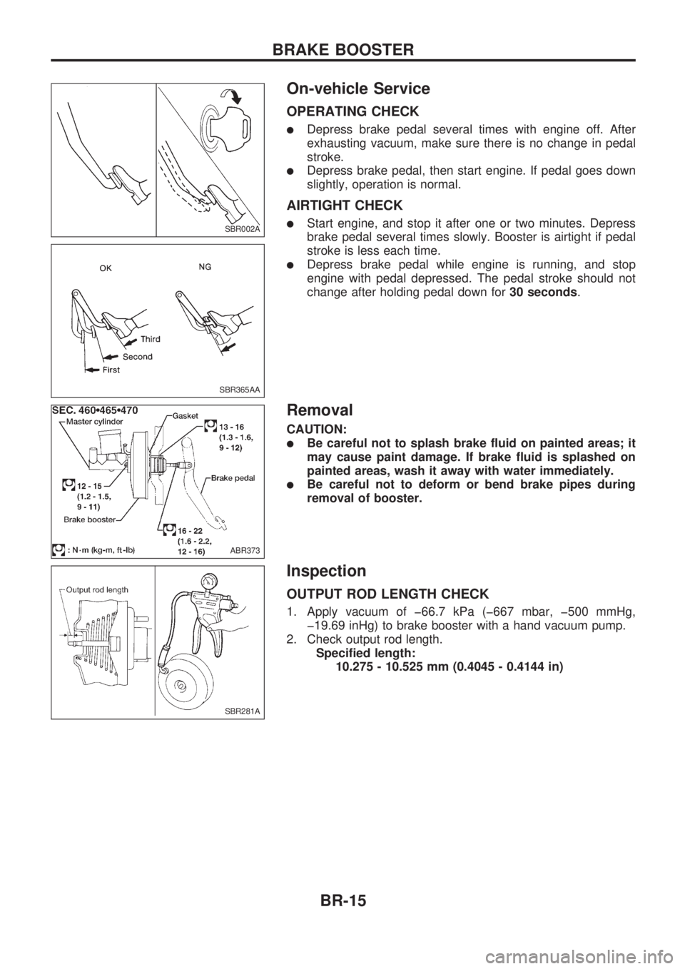
On-vehicle Service
OPERATING CHECK
lDepress brake pedal several times with engine off. After
exhausting vacuum, make sure there is no change in pedal
stroke.
lDepress brake pedal, then start engine. If pedal goes down
slightly, operation is normal.
AIRTIGHT CHECK
lStart engine, and stop it after one or two minutes. Depress
brake pedal several times slowly. Booster is airtight if pedal
stroke is less each time.
lDepress brake pedal while engine is running, and stop
engine with pedal depressed. The pedal stroke should not
change after holding pedal down for30 seconds.
Removal
CAUTION:
lBe careful not to splash brake fluid on painted areas; it
may cause paint damage. If brake fluid is splashed on
painted areas, wash it away with water immediately.
lBe careful not to deform or bend brake pipes during
removal of booster.
Inspection
OUTPUT ROD LENGTH CHECK
1. Apply vacuum of þ66.7 kPa (þ667 mbar, þ500 mmHg,
þ19.69 inHg) to brake booster with a hand vacuum pump.
2. Check output rod length.
Specified length:
10.275 - 10.525 mm (0.4045 - 0.4144 in)
SBR002A
SBR365AA
ABR373
SBR281A
BRAKE BOOSTER
BR-15
Page 20 of 1659
Installation
CAUTION:
lBe careful not to deform or bend brake pipes during
installation of booster.
lReplace clevis pin if damaged.
lRefill with new brake fluid DOT 3 or DOT 4*1.
lNever reuse drained brake fluid.
lTake care not to damage brake booster mounting bolt
thread when installing. Due to the narrow angle of
installation, the threads can be damaged by the dash
panel.
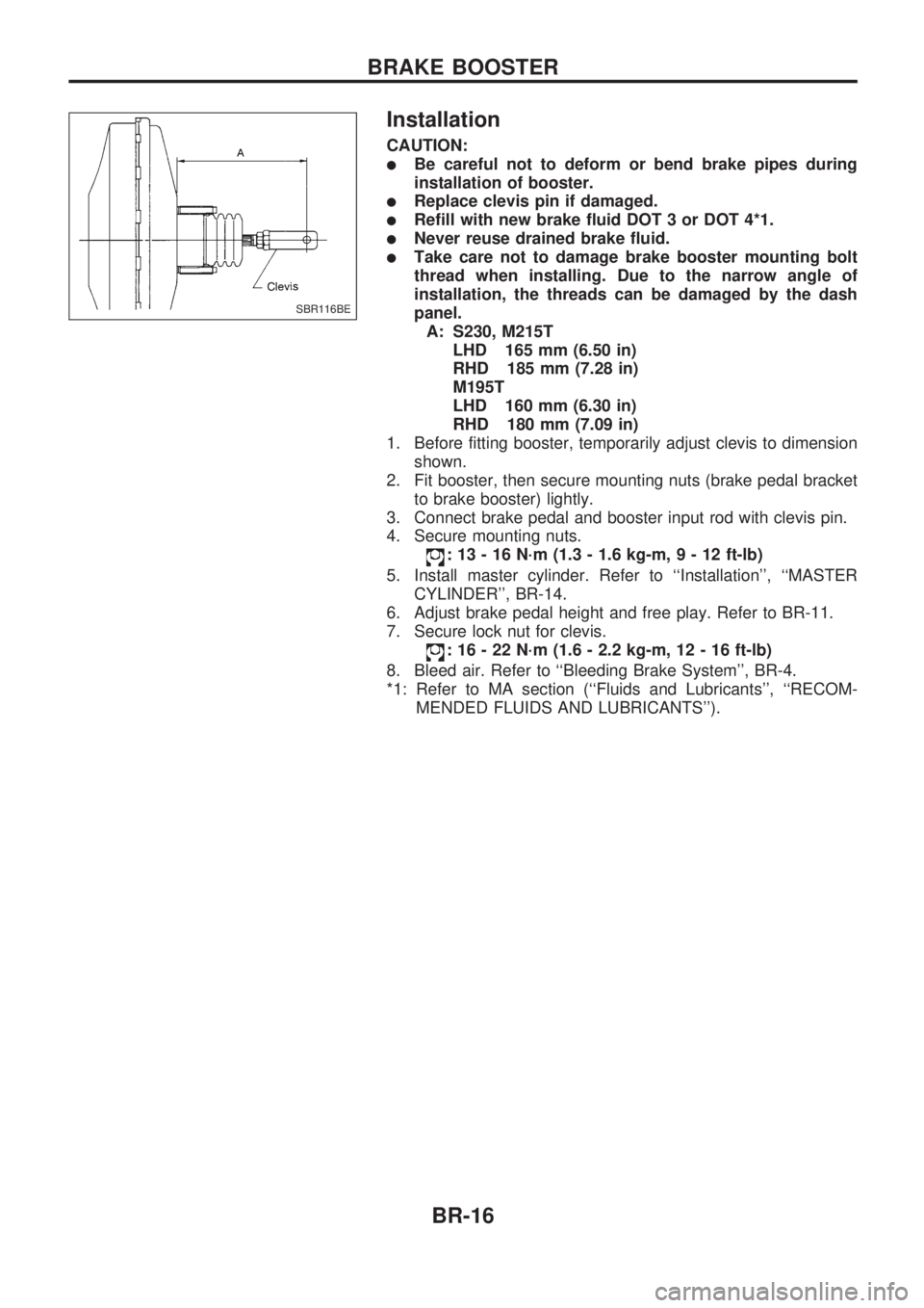
A: S230, M215T
LHD 165 mm (6.50 in)
RHD 185 mm (7.28 in)
M195T
LHD 160 mm (6.30 in)
RHD 180 mm (7.09 in)
1. Before fitting booster, temporarily adjust clevis to dimension
shown.
2. Fit booster, then secure mounting nuts (brake pedal bracket
to brake booster) lightly.
3. Connect brake pedal and booster input rod with clevis pin.
4. Secure mounting nuts.
: 13 - 16 N´m (1.3 - 1.6 kg-m,9-12ft-lb)
5. Install master cylinder. Refer to ``Installation'', ``MASTER
CYLINDER'', BR-14.
6. Adjust brake pedal height and free play. Refer to BR-11.
7. Secure lock nut for clevis.
: 16 - 22 N´m (1.6 - 2.2 kg-m, 12 - 16 ft-lb)
8. Bleed air. Refer to ``Bleeding Brake System'', BR-4.
*1: Refer to MA section (``Fluids and Lubricants'', ``RECOM-
MENDED FLUIDS AND LUBRICANTS'').
SBR116BE
BRAKE BOOSTER
BR-16
Page 25 of 1659
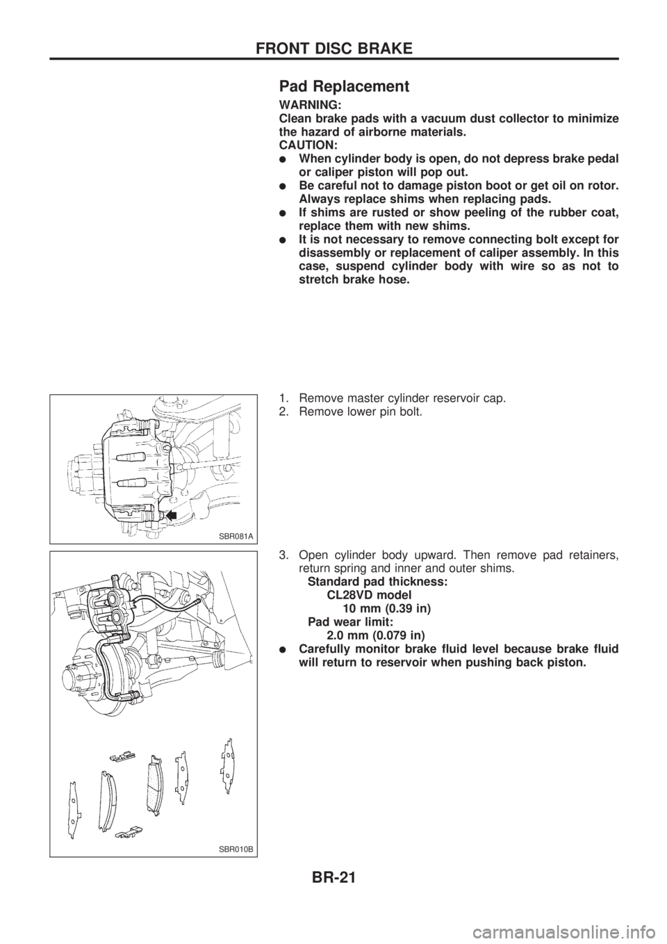
Pad Replacement
WARNING:
Clean brake pads with a vacuum dust collector to minimize
the hazard of airborne materials.
CAUTION:
lWhen cylinder body is open, do not depress brake pedal
or caliper piston will pop out.
lBe careful not to damage piston boot or get oil on rotor.
Always replace shims when replacing pads.
lIf shims are rusted or show peeling of the rubber coat,
replace them with new shims.
lIt is not necessary to remove connecting bolt except for
disassembly or replacement of caliper assembly. In this
case, suspend cylinder body with wire so as not to
stretch brake hose.
1. Remove master cylinder reservoir cap.
2. Remove lower pin bolt.
3. Open cylinder body upward. Then remove pad retainers,
return spring and inner and outer shims.
Standard pad thickness:
CL28VD model
10 mm (0.39 in)
Pad wear limit:
2.0 mm (0.079 in)
lCarefully monitor brake fluid level because brake fluid
will return to reservoir when pushing back piston.
SBR081A
SBR010B
FRONT DISC BRAKE
BR-21
Page 26 of 1659
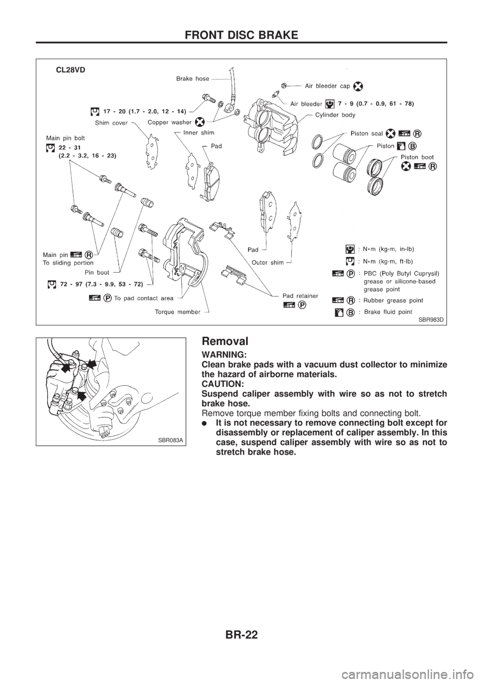
Removal
WARNING:
Clean brake pads with a vacuum dust collector to minimize
the hazard of airborne materials.
CAUTION:
Suspend caliper assembly with wire so as not to stretch
brake hose.
Remove torque member fixing bolts and connecting bolt.
lIt is not necessary to remove connecting bolt except for
disassembly or replacement of caliper assembly. In this
case, suspend caliper assembly with wire so as not to
stretch brake hose.
SBR983D
SBR083A
FRONT DISC BRAKE
BR-22
Page 27 of 1659
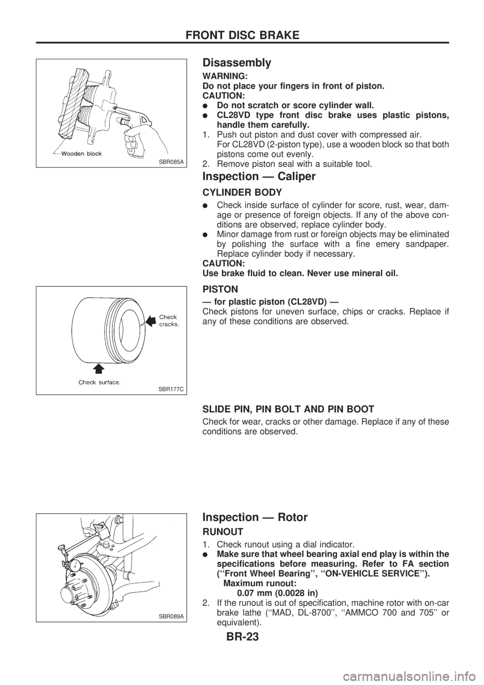
Disassembly
WARNING:
Do not place your fingers in front of piston.
CAUTION:
lDo not scratch or score cylinder wall.
lCL28VD type front disc brake uses plastic pistons,
handle them carefully.
1. Push out piston and dust cover with compressed air.
For CL28VD (2-piston type), use a wooden block so that both
pistons come out evenly.
2. Remove piston seal with a suitable tool.
Inspection Ð Caliper
CYLINDER BODY
lCheck inside surface of cylinder for score, rust, wear, dam-
age or presence of foreign objects. If any of the above con-
ditions are observed, replace cylinder body.
lMinor damage from rust or foreign objects may be eliminated
by polishing the surface with a fine emery sandpaper.
Replace cylinder body if necessary.
CAUTION:
Use brake fluid to clean. Never use mineral oil.
PISTON
Ð for plastic piston (CL28VD) Ð
Check pistons for uneven surface, chips or cracks. Replace if
any of these conditions are observed.
SLIDE PIN, PIN BOLT AND PIN BOOT
Check for wear, cracks or other damage. Replace if any of these
conditions are observed.
Inspection Ð Rotor
RUNOUT
1. Check runout using a dial indicator.
lMake sure that wheel bearing axial end play is within the
specifications before measuring. Refer to FA section
(``Front Wheel Bearing'', ``ON-VEHICLE SERVICE'').
Maximum runout:
0.07 mm (0.0028 in)
2. If the runout is out of specification, machine rotor with on-car
brake lathe (``MAD, DL-8700'', ``AMMCO 700 and 705'' or
equivalent).
SBR085A
SBR177C
SBR089A
FRONT DISC BRAKE
BR-23
Page 28 of 1659
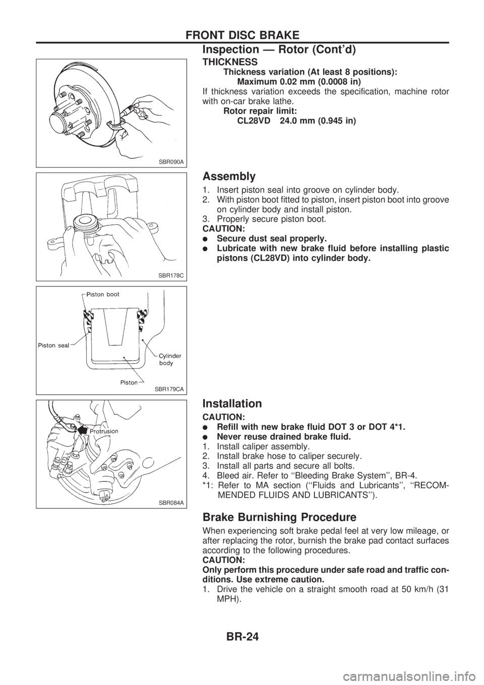
THICKNESS
Thickness variation (At least 8 positions):
Maximum 0.02 mm (0.0008 in)
If thickness variation exceeds the specification, machine rotor
with on-car brake lathe.
Rotor repair limit:
CL28VD 24.0 mm (0.945 in)
Assembly
1. Insert piston seal into groove on cylinder body.
2. With piston boot fitted to piston, insert piston boot into groove
on cylinder body and install piston.
3. Properly secure piston boot.
CAUTION:
lSecure dust seal properly.
lLubricate with new brake fluid before installing plastic
pistons (CL28VD) into cylinder body.
Installation
CAUTION:
lRefill with new brake fluid DOT 3 or DOT 4*1.
lNever reuse drained brake fluid.
1. Install caliper assembly.
2. Install brake hose to caliper securely.
3. Install all parts and secure all bolts.
4. Bleed air. Refer to ``Bleeding Brake System'', BR-4.
*1: Refer to MA section (``Fluids and Lubricants'', ``RECOM-
MENDED FLUIDS AND LUBRICANTS'').
Brake Burnishing Procedure
When experiencing soft brake pedal feel at very low mileage, or
after replacing the rotor, burnish the brake pad contact surfaces
according to the following procedures.
CAUTION:
Only perform this procedure under safe road and traffic con-
ditions. Use extreme caution.
1. Drive the vehicle on a straight smooth road at 50 km/h (31
MPH).
SBR090A
SBR178C
SBR179CA
SBR084A
FRONT DISC BRAKE
Inspection Ð Rotor (Cont'd)
BR-24